Graco LineLazer IV 200HS Repair And Parts Manual
Auto-layout system
airless line striper
Hide thumbs
Also See for LineLazer IV 200HS:
- Repair and parts list (40 pages) ,
- Operation (54 pages) ,
- Installation and operation manual (33 pages)
Table of Contents
Advertisement
Repair - Parts List
™
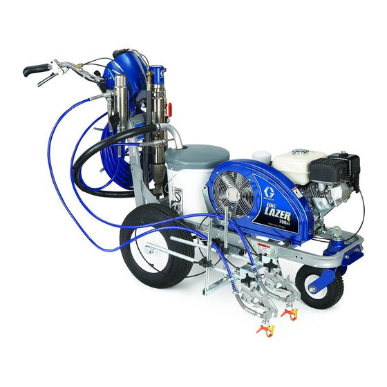
LineLazer
Airless Line Striper
For application of line striping materials. For professional use only.
Not for use in explosive atmospheres.
3300 psi (22.8 MPa, 228 bar) Maximum Working Pressure
Important Safety Instructions
Read all warnings and instructions in this manual.
Save these instructions.
See page 2 for model information.
312190
309277
311254
IV 200
Auto-Layout
HS
309055
312345
312307
™
System
312226P
EN
ti10234a
Advertisement
Table of Contents

Related Manuals for Graco LineLazer IV 200HS


Summary of Contents for Graco LineLazer IV 200HS
- Page 1 Repair - Parts List ™ ™ LineLazer IV 200 Auto-Layout System 312226P Airless Line Striper For application of line striping materials. For professional use only. Not for use in explosive atmospheres. 3300 psi (22.8 MPa, 228 bar) Maximum Working Pressure Important Safety Instructions Read all warnings and instructions in this manual.
-
Page 2: Table Of Contents
Hydraulic Pump ......17 Graco Information ......40... -
Page 3: Warnings
Warnings Warnings The following warnings are for the setup, use, grounding, maintenance, and repair of this equipment. The exclama- tion point symbol alerts you to a general warning and the hazard symbol refers to procedure-specific risk. Refer back to these warnings. Additional, product-specific warnings may be found throughout the body of this manual where applicable. - Page 4 Warnings WARNING EQUIPMENT MISUSE HAZARD Misuse can cause death or serious injury. • Do not operate the unit when fatigued or under the influence of drugs or alcohol. • Do not exceed the maximum working pressure or temperature rating of the lowest rated system component.
-
Page 5: Tip Selection
Tip Selection Tip Selection (cm) (cm) (cm) (cm) LL5213* 2 (5) LL5215* 2 (5) LL5217 4 (10) LL5219 4 (10) LL5315 4 (10) LL5317 4 (10) LL5319 4 (10) LL5321 4 (10) LL5323 4 (10) ... -
Page 6: General Repair Information
General Repair Information General Repair Information grounding clamp 1. Keep all screws, nuts, washers, gaskets, and electrical fittings removed during repair proce- dures. These parts are not normally provided with replacement assemblies. 2. Test repair after problem is corrected. water pipe, steel sign post, or 3. -
Page 7: Maintenance
YEARLY OR 2000 HOURS: Replace hydraulic oil and Always engage the trigger lock when you stop spraying filter element with Graco hydraulic oil 169236 (5 gal- to prevent the gun from being triggered accidentally by lon/18.9 liter) or 207428 (1 gallon/3.8 liter) and filter ele- hand or if dropped or bumped. -
Page 8: Troubleshooting
Set pump valve OFF. Turn pressure down. Turn engine OFF. Pry rod up or down until hydraulic motor shifts. * Check hydraulic fluid level often. Do not allow it to become too low. Use only Graco approved hydraulic fluid, page 7. 312226P... - Page 9 Troubleshooting Problem Cause Solution Displacement pump Piston ball is not seating. Service piston ball. Manual 309277. operates, but output is Piston packings are worn or damaged. Replace packings. Manual 309277. low on upstroke Displacement pump Strainer (34e) is clogged. Clean strainer. operates but output is low O-ring in pump is worn or damaged.
- Page 10 Intake line to pump inlet is not tight. Tighten. Hydraulic motor is worn or damaged. Bring sprayer to Graco distributor for repair. Large pressure drop in fluid hose. Use larger diameter or shorter hose. The sprayer overheats. Paint buildup on hydraulic components.
- Page 11 Troubleshooting Problem Cause Solution Spray icon does not show Loose connector. Check that 5-pin connector and reed switch are on display when fluid is properly connected. sprayed. Interrupter (164) is improperly positioned. Turn screw counterclockwise until spray icon syn- chronizes with fluid spray. Reed switch assembly (18) is damaged.
-
Page 12: Auto-Layout Can Actuator Adjustment
Auto-Layout Can Actuator Adjustment Auto-Layout Can Actuator Adjustment Adjustments The can actuator is set at the factory. If the dot size is not as desired, do the coarse and/or fine adjustments. Coarse Adjustment Locate four screws on side of holder base. ti10072a Carefully tighten screws. -
Page 13: Auto-Layout System
Auto-Layout System Auto-Layout System Engine Stop Switch 4. Note on paper, lead connections to the control board. Disconnect leads from control board (15d). Removal 5. Remove six screws (15k) from control board. Installation 1. F . 2. Install control board (15d) and six screws (15k). - Page 14 Auto-Layout System GROUND TO ENGINE Main Control Box Cable Transducer ti10327a 312226P...
-
Page 15: Control Board Diagnostics
Control Board Diagnostics Control Board Diagnostics Display Messages Relieve pressure before repair; page 7. No display does not mean that sprayer is not pressurized. Display Sprayer Operation Indication Action No Display Sprayer may be pres- Loss of power or dis- Check power source. -
Page 16: Trigger Sensor Adjustment
Trigger Sensor Adjustment Trigger Sensor Adjustment Refer to Troubleshooting for trigger sensor adjust- ment, and see Operation Manual 312190. Distance Sensor Replacement 1. Remove wheel (120) from LineLazer. 3. Install new distance sensor (66) and spacer (272) with wire clamp (115) and screw (273). 2. -
Page 17: Hydraulic Pump
11. Loosen set screw (102) and remove remote pres- N•m). Install oil filter (199); tighten 3/4 turn after gas- sure control cable (12). ket contacts base. Fill with Graco hydraulic oil, page 12. Remove eight screws (184), reservoir cover (237), filter assembly (A) and gasket (85). - Page 18 Hydraulic Pump TI6551a 312226P...
-
Page 19: Fan Belt
Fan Belt Fan Belt Removal 5. Remove belt from fan pulley (86) and fan pulley (87a). Installation 1. Thread belt (143) around fan pulley (87a) and fan pulley (86). 1. Relieve pressure, page 7. 2. Lower engine (185) to put tension on belt. 2. -
Page 20: Engine
Engine Engine Removal 7. Remove four screws (189), washers (114), washers (170) and nuts (118) and remove rocker plate, dampeners (59) and washers (114) from engine. All service to the engine must be performed by an authorized HONDA dealer. 1. Relieve pressure, page 7. Installation 2. -
Page 21: Hydraulic Motor Rebuild
6. Start engine and operate pump for 30 seconds. from hydraulic motor cylinder (69). Turn engine OFF. Check hydraulic oil level and fill with Graco hydraulic oil, page 7. FLYING PARTS HAZARD Detent spring has high energy potential. If detent spring is released without due care detent spring and balls could fly into the eyes of the disassembler. - Page 22 Hydraulic Motor Rebuild Test Hole ti8817a TI8818a 312226P...
-
Page 23: Oil/Filter Change
1. Install drain plug (195). Apply a light coat of oil to oil filter gasket and install oil filter (199). Tighten oil fil- ter 3/4 turn after gasket contacts base. 2. Fill with 1.25 gallons (4.73 liters) of Graco hydraulic oil 169236 (5 gallon/20 liter) or 207428 (1 gallon/3.8 ti2271a... -
Page 24: Displacement Pump
12. Push pin (249) into hole. Push magnet ring (222) . 12 down. Push retaining spring (194) into groove. 5. F . 13. Loosen jam nut. Unscrew pump. TI6518a . 15 3. F . 16. Fill packing nut with Graco TSL. 312226P... -
Page 25: Parts
Parts Parts LineLazer IV 200 Parts Page 30 Parts Page 32 Parts Page 34 Parts Page 28 Parts Page 36 Parts Page 26 Parts Page 29 Sheet 1 of 7 ti10325a 312226P... - Page 26 Parts TI14596A To remove cover (257), press tabs together and pull cover away from plate (99). Sheet 2 of 7 312226P...
- Page 27 Parts LineLazer IV 200 Part Description Ref Part Description 237686 CLAMP, grounding assy 108868 CLAMP, wire 245225 HOSE, 3/8 in. x 50 ft 110837 SCREW, flange, hex 287623 FRAME, linestriper (painted) 255162 WHEEL, pneumatic 287417 HANDLE 111040 NUT, lock, insert, nylock, 5/16 287622 SUPPORT, handle, painted 111194...
- Page 28 Parts LineLazer IV 200 136a Ref 14 ti27326a Ref 144 Ref 27 Ref 161 Torque to 90-110 in-lb. Sheet 3 of 7 Torque to 10-20 in-lb. TI6497a TI6497a TI6497a 312226P...
- Page 29 Parts LineLazer IV 200 Part Description Part Description 15F624 NUT, cable, gun 224052 BRACKET, support gun 119647 SCREW, cap, socket, flthd 248157 GUN, flex, basic, includes guard & tip 119648 SCREW, mach tursshd, cross recess 287570 KIT, holder, gun 101566 NUT, lock 287569 HOLDER, gun...
- Page 30 Parts LineLazer IV 200 SOFTWARE REVISION LABEL Ref 100 Ref 14 ti17487b ti17487a Sheet 4 of 7 312226P...
- Page 31 Parts LineLazer IV 200 Part Description Part Description 196178 ADAPTER, nipple 245103 VALVE, drain 196181 FITTING, nipple 193709 SEAT, valve 104813 PLUG, pipe 193710 SEAT, valve LABEL, kit, blank 116424 NUT, cap 15K102 HARNESS, wiring 114708 SPRING 117501 SCREW, mach, slot, hex wash hd 244067 FILTER, fluid 118359 KNOB, pressure control 287687 KIT, repair, pressure control...
- Page 32 Parts LineLazer IV 200 Torque to 130-150 in-lb. Torque to 150 ft-lb Torque to 40 ft-lb Torque to 25 ft-lb Sheet 5 of 7 TI6499d 312226P...
- Page 33 196176 ADAPTER, nipple 231* 15B063 LABEL, 69 246176 SLEEVE, hydraulic cylinder, 107210 SCREW, cap, socket head 235 15B804 LABEL, Graco Logo includes 213 243* 178179 WASHER, sealing 193394 NUT, retaining 244*‡ 178207 BEARING, piston 117441 VALVE, ball 245*‡ 178226 SEAL, piston...
- Page 34 Parts LineLazer IV 200 Ref 32 Detail 34 Sheet 6 of 7 TI6493b 312226P...
- Page 35 Parts LineLazer IV 200 Part Description Part Description 100002 SCREW, set, sch 287687 SHAFT, flexible, includes 102, 100023 WASHER, flat 288261 RAIL, belt 100084 BALL, metallic 288734 GUARD, belt, includes 162, 193, 102040 NUT, lock 214, 224, 228 107188 O-RING 15E476 BRACKET, retainer, motor 156401 O-RING 170957 TUBE, suction...
- Page 36 Parts LineLazer IV 200 Ref 141 Detail A Detail A Sheet 7 of 7 Install washers (130) concave surface to inside. TI6404b 312226P...
- Page 37 Parts LineLazer IV 200 Swivel Wheel Assembly 240719 Part Description Part Description 112405 NUT, lock 240942 SHAFT, fork 112776 WASHER, plain 240991 BRACKET, caster, front 119563 SPRING, Belleville 15G952 BRACKET, hub 113471 SCREW, cap, hex hd 181818 KNOB, pronged 132* 113484 SEAL, grease 193528 ARM, detent 133* 113485 BEARING, cup/cone 193658 SPACER, seal...
-
Page 38: Auto-Layout System Wiring Diagram
Auto-Layout System Wiring Diagram Auto-Layout System Wiring Diagram Red clip on yellow YELLOW WHITE/YELLOW 5900 TO ENGINE WHITE/RED GROUND ENGINE OFF TRANSDUCER SWITCH DISPLAY BOARD SOLENOID CONNECTOR REMOTE BUTTON DISTANCE SENSOR GUN TRIGGER J9 J8 PUMP JUNCTION ON/OFF SWITCH J4 J3 SOFTWARE REVISION J1 J2... -
Page 39: Technical Data
Wetted parts ........PTFE, Nylon, polyurethane, V-Max ™ UHMW polyeth- ylene, fluoroelastomer, acetal, leather, tungsten carbide, stainless steel, chrome plating, nickel-plated carbon steel, ceramic Accessories Must be purchased separately. GRACO-APPROVED HYDRAULIC OIL 169236 5 gallons (19 liters) 207428 1 gallon (3.8 liters) 312226P... -
Page 40: Graco Standard Warranty
With the exception of any special, extended, or limited warranty published by Graco, Graco will, for a period of twelve months from the date of sale, repair or replace any part of the equipment determined by Graco to be defective.