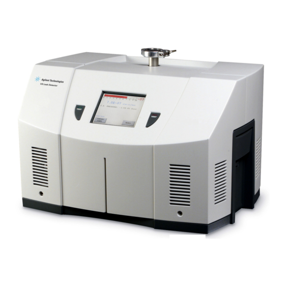
Agilent Technologies VS Series Operation Manual
Component leak detector
Hide thumbs
Also See for VS Series:
- Operation manual (158 pages) ,
- Field installation instructions (18 pages) ,
- Quick reference card (2 pages)

Related Manuals for Agilent Technologies VS Series


Summary of Contents for Agilent Technologies VS Series
- Page 1 Vacuum Products Division VS Series OPERATIONS MANUAL Component Leak Detector Manual Number: 699909948 Revision C March 2011...
- Page 2 VS Series Component Leak Detector Copyright 2011 Agilent Inc.
-
Page 3: Table Of Contents
Pumps ..........................xxiii Agilent Services ........................xxiv Contacting Agilent ........................xxv Section 1. Introduction to the VS Series Component Leak Detector ..........1-1 1.1 The VS Series Component Leak Detector ................1-1 1.1.1 VS Series Component Leak Detector Configurations ..........1-3 1.2 Unpacking the Leak Detector .................... - Page 4 VS Series Component Leak Detector Section 2. Operating the VS C-15 Leak Detector via Front Panel Display ........2-1 2.6.1 Power Up Sequence ....................2-2 2.1 Initial Startup and Shutdown ....................2-3 2.1.1 Startup ........................2-3 2.1.2 Calibrated Leak ......................2-4 2.1.3 Shutdown ........................
- Page 5 6.1.1 Sensitivity Check ......................6-4 6.2 Spare Parts List ........................6-5 6.3 Leak Detector Accessory Item List ..................6-6 Appendix A. VS Series Leak Detector Hardware Descriptions ............A-1 A.1 Spectrometer Tube Description ...................A-2 A.2 Printed Circuit Boards P/Ns and Descriptions ..............A-3 A.2.1 CPU PCB ........................A-3...
- Page 6 VS Series Component Leak Detector Appendix C. Troubleshooting ......................C-1 C.1 Service 1/Service 2 Commands ..................C-1 C.1.1 SERVICE1 .........................C-1 C.1.2 SERVICE2 .........................C-2 C.2 System Pressure Wait error message appears on the front panel display ......C-3 C.3 Operational Failures ......................C-10 C.4 Performance Issues ......................C-14 Appendix D.
- Page 7 VS Series Component Leak Detector Figures VS C15 Base Unit, Outline Drawing ................... 1-3 VS C-15 Display Unit Physical Dimensions: Front and Side ..........1-4 C-15 Interconnection Diagram .................... 1-7 VS C-15 Base Unit Front Panel ..................1-9 VS C-15 Display Front Panel ....................1-9 VS C-15 Base Unit Rear Panel..................
- Page 8 VS Series Component Leak Detector Calibrated Leak O-ring......................B-4 NW25 Clamp To Spectrometer...................B-5 NW25 Clamp To Spectrometer...................B-5 Pump Feet Nuts ........................B-5 Test Port Connection ......................B-6 Pump To Mounting Assembly .....................B-6 Unit Top Screws .........................B-8 B-10 Fan Connector ........................B-8 B-11 Fan Filter..........................B-9 B-12 Fan Exterior Screws ......................B-9...
- Page 9 VS Series Component Leak Detector B-49 Cables To Spectrometer ....................B-35 B-50 Spectrometer Cover Screws .....................B-35 B-51 Spectrometer Header Assembly Screws ................B-36 B-52 Spectrometer Assembly Removal..................B-36 B-53 O-ring ..........................B-37 B-54 Inside of Spectrometer Body.....................B-37 B-55 Header Assembly Screws....................B-38 B-56 Ion Source Header Pin Schematic..................B-39 B-57 Unit Top Screws........................B-40...
- Page 10 VS Series Component Leak Detector Measuring Leaks: Outside In ....................D-4 Measuring Leaks: Inside Out ....................D-5 Locating Leaks: Inside Out ....................D-5 Accumulation: Inside Out ....................D-6 Vacuum System........................D-7 VS C15 Interconnection Diagram ..................E-2...
- Page 11 Tables Installation Requirements ....................1-6 Base Unit Rear Panel Components ................. 1-12 Display Unit Rear Panel Components ................1-14 VS Series VS-C-15 Features ................... 1-16 Dynamic Range Specification ..................1-18 VS C15 Startup Scenario....................2-3 General Description ......................2-7 Basic Soft Button Functional Items ..................2-9 On-Screen Icons ......................
- Page 12 VS Series Component Leak Detector This page intentionally left blank.
- Page 13 VS Series Component Leak Detectors to which this declaration relates is in conformity with the following standards: Safety: •...
-
Page 14: Preface
VS Series Component Leak Detectors Preface Documentation Standards This manual uses the following documentation standards: Notes contain important information. NOTE Cautions appear before instructions, which if not followed, CAUTION could cause damage to the equipment or data loss. Warnings appear for a particular procedure or practice which, if WARNING not followed correctly, could lead to serious injury or death. -
Page 15: Hazard And Safety Information
VS Series Component Leak Detectors Hazard and Safety Information The common international symbols used in this manual and on the equipment are defined below. ° OFF Supply (Power) Earth (Ground) Terminal ON Supply (Power) Caution, Hot Surface AC – Alternating Current... -
Page 16: Solvents
VS Series Component Leak Detectors Solvents The mechanical components of leak detectors are typically WARNING cleaned with alcohol, methanol, or other solvents. When heated, sprayed, or exposed to high-temperature equipment, these solvents become flammable and explosive, causing serious injury or death. Do not use these solvents near a high-temperature source. -
Page 17: O-Ring Care
VS Series Component Leak Detectors O-ring Care When removing, checking or replacing O-rings, keep in mind the following: Agilent recommends replacing all O-rings during routine NOTE maintenance or during any maintenance procedure requiring that O-rings be removed. Due to the effective cleaning nature of VacuSolv solvent and NOTE its residue-free properties, Agilent’... -
Page 18: Equipment, General
VS Series Component Leak Detectors Equipment, General Environment of intended use: Indoors use in an industrial and laboratory installation only. Altitude up to 2000m POLLUTION DEGREE 2, Overvoltage Category: I, Class III (DC powered) Operating Temperature: +5 °C to +48 °C, Relative Humidity (RH) up to 80% max. -
Page 19: Power And Static Sensitivity
VS Series Component Leak Detectors LCD Display If the LCD display breaks, avoid getting any liquid crystal in mouth WARNING or eyes. If it gets on the operator hands, feet or clothing, wash it immediately with soap and water. Do not apply excessive pressure to the LCD display as this may CAUTION cause smears. - Page 20 VS Series Component Leak Detectors Figure 1 24VDC Input Power Connection Provide the 24 VDC power to an optional VS C15 Display Unit via a High Density 15-pin D-Sub M/F cable connected to the DISPLAY connector on the rear panel of the Base Unit as shown below.
- Page 21 VS Series Component Leak Detectors This equipment has been tested and found to comply with the CAUTION limits for Class A digital device, pursuant to Part 15 of FCC Rules. These limits are designed to provide reasonable protection against harmful interference when it is operated in a commercial environment.
- Page 22 VS Series Component Leak Detectors This equipment is designed to meet current EEC regulations: WARNING LVD (Low Voltage Directive, 2006/95/EC of 21 December 2006) and EMC (Electromagnetic Compatibility Directive, 2004/108/EEC of 31 December 2004) for Pollution Degree 2, Overvoltage Category I, Class III (DC powered) environment for Industrial, Scientific, Measuring and Process Control Electrical Equipment.
-
Page 23: Spectrometer
VS Series Component Leak Detectors Spectrometer Store the Ion Source/Preamplifier sub-assembly in a cool, dry WARNING area in a tightly sealed, ESD protected container. Wear lint-free gloves when handling the spectrometer. Wash hands thoroughly after handling the spectrometer filaments and especially before smoking or eating. -
Page 24: Agilent Services
VS Series Component Leak Detectors To avoid injury, wait until the turbo pump is completely WARNING stopped before disconnecting it from the vacuum system. To vent the turbo, open the knurled vent screw located on the side of the turbo. If the turbo is spinning, you will hear it wind down. -
Page 25: Section 1. Introduction To The Vs Series Component Leak Detector
Component Leak Detector 1.1 The VS Series Component Leak Detector The VS Component Leak Detector is a version of the VS Series wide-range Helium Mass Spectrometer Leak Detectors with a new concept to integrate the whole leak detector into portable compact units for easy installation into an OEM leak detection system:... - Page 26 VS Series Component Leak Detector To provide instant Profinet Real Time connectivity, install the Profinet IO module (VSCFACPN or VSCFLDPN) into the VSC15BU unit and use a shielded Category 5E min Ethernet cable with RJ45 plug (ISO/IEC 11801, Edition 2) between the VSC15BU unit and a Profinet host controller.
-
Page 27: Vs Series Component Leak Detector Configurations
VS Series Component Leak Detector 1.1.1 VS Series Component Leak Detector Configurations This section contains outline drawings of the Base, VSC15BU, and Display, VSC15DU, units. Dimensions are given in inches, in brackets, and in mm, below the brackets. Figure 1-1 shows the outline drawing and physical dimensions of the VS C15 System unit... -
Page 28: Vs C-15 Display Unit Physical Dimensions: Front And Side
VS Series Component Leak Detector Figure 1-2 shows the outline drawing and physical dimensions of a VS C-15 Display Unit. Figure 1-2 VS C-15 Display Unit Physical Dimensions: Front and Side... -
Page 29: Unpacking The Leak Detector
1.2 Unpacking the Leak Detector The following items are included in the shipment: VS Series Component Leak Detector Operations Manual VS Series Component Leak Detector configured and completely assembled as ordered All necessary cables, as ordered Turbo Pump manual (CD) -
Page 30: Installation
VS Series Component Leak Detector 1.3 Installation Read the Preface for all operational warnings and cautions. CAUTION The VS Series Component Leak Detector is delivered completely assembled as ordered. Installation requirements are described in Table 1-2. Table 1-1 Installation Requirements Item... -
Page 31: Typical Vs- C-15 Leak Detection System Interconnection Diagram
VS Series Component Leak Detector Table 1-1 Installation Requirements A primary vacuum pump with a minimal pumping 285-300 l/m (10 Foreline Pump cfm) for use as a Foreline/(Roughing) Test Pump for a single pump configuration system. Recommended: Agilent's DS302 Rotary Vane Mechanical pump. -
Page 32: Helium
Adequate circulation to prevent an increased helium background level. 1.3.4 Storage If the VS Series Component leak detector Base and Display units are not used immediately, it can be stored as received without special precautions. A dry, relatively dust-free area is preferred. -
Page 33: Front Panels
VS Series Component Leak Detector 1.4 Front Panels 1.4.1 VS C-15 Base Unit The VS C15 Base unit front panel (Figure 1-4) has an opening for a single NW25 flange that provides vacuum connection to a user leak detection system. - Page 34 VS Series Component Leak Detector The VS C-15 Displays touch panel is calibrated at the factory and should not require recalibration. If the touch panel buttons do not respond to pushes, recalibrate as follows: 1. Turn off the leak detector power.
- Page 35 VS Series Component Leak Detector Pressures Bar Graph The small bar graph displays the Test Port Pressure in the logarith- mic format. Series of screens with the soft key buttons for operator interface. An operator interfaces the leak detector functions through a series of screens, which are navigated as shown in Section 2.2.1 “Screens...
-
Page 36: Rear Panel
VS Series Component Leak Detector 1.5 Rear Panel 1.5.1 VS C-15 Base Unit The rear panel of VS C-15 Base Unit with an optional ProfiNet-I/O Module is shown in Figure 1-6. Figure 1-6 VS C-15 Base Unit Rear Panel Table 1-2 gives the rear panel pin assignments and descriptions. - Page 37 VS Series Component Leak Detector Table 1-2 Base Unit Rear Panel Components (Continued) Name Description POWER Green LED light indicates 24 VDC ON Power Entry Module Provides 24 VDC supply power connection and EMI protection for the VS C-15 Base unit. The Power Entry Module consists of: DC Power Input Connector - three-prong grounded Inlet connector that is compatible with the Molex’s HCS-125 Receptacle, P/N 03-12-1036 10 A EMC line filter...
-
Page 38: Vs C15 Display Unit
VS Series Component Leak Detector 1.5.2 VS C15 Display Unit The rear panel of VS C15 Display Unit is shown in Figure 1-7. Figure 1-7 VS C-15 Component Display Unit Rear Panel Table 1-3 gives the rear panel pin assignments and descriptions. -
Page 39: Features
ProfiNet -IO module to interface with the ProfiNet industrial network via an Ethernet connection. The features for the VS Series VS C15 leak detector are provided in Table 1-4. Ordering information is given in Table 6-4 on page 6-5. 1-15... -
Page 40: Vs Series Vs-C-15 Features
VS Series Component Leak Detector Table 1-4 VS Series VS-C-15 Features Feature Description Calibration Fully automated tuning and calibration using the internal or external calibrated leak. Agilent’s patent-pending electronic calibration system provides precise and fast calibration across the entire leak range with one standard leak. - Page 41 VS Series Component Leak Detector Table 1-4 VS Series VS-C-15 Features (Continued) Feature Description Pressure Indication An optional ConvecTorr gauge can be installed on the customer system and connected to VS C15 Base unit via a dedicated rear panel CONVECTORR GAUGE connector.
-
Page 42: Dynamic Range Specification
VS Series Component Leak Detector Table 1-5 gives the Dynamic Range Specification by range. Table 1-5 Dynamic Range Specification Displayed Ranges Maximum Test Pressure / Crossover Pressure = 5 Torr Turbo Speed = 80K RPM Displayed Ranges Maximum Test Pressure /... -
Page 43: Section 2. Operating The Vs C-15 Leak Detector Via Front Panel Display
VS Series Component Leak Detector Section 2. Operating the VS C-15 Leak Detector via Front Panel Display This section defines how to navigate and operate the VS C15 component leak detector via the optional front panel display. Before an initial startup verify that:... -
Page 44: Power Up Sequence
VS Series Component Leak Detector 2.6.1 Power Up Sequence The power up sequence is: 1. 24 VDC is applied to the VS-C15 and the turbo pump ramps up to the programmed RPM value for the selected working range. During this time the system is not ready. -
Page 45: Initial Startup And Shutdown
VS Series Component Leak Detector 2.1 Initial Startup and Shutdown 2.1.1 Startup To start the VS C-15 leak detector: 1. Plug the 24 VDC power cable into the 24 VDC inlet on the VS C-15 Base unit rear panel. Move the local branch power switch/circuit breaker in the ON position. -
Page 46: Calibrated Leak
VS Series Component Leak Detector 2.1.2 Calibrated Leak 2.1.2.1 Internal calibration via the Front Panel Display Perform an internal calibration (if installed) to verify that the leak detector is functional and is ready for testing Verify that the correct information for the internal calibrated... -
Page 47: Shutdown
VS Series Component Leak Detector 2.1.2.2 Full External Calibration via the Front Panel Display Manual full external calibration (Tune, Offset, & Ext. Calibration) Select and program the desired working range and external calibrated leak value prior to calibration. Perform a full external calibration to verify that the leak detector is functional if an internal calibrated leak is not installed. -
Page 48: Vs C-15 Display
VS Series Component Leak Detector 2.2 VS C-15 Display The optional VS C-15 Display unit with Touch Panel is used for the initial set-up and configuration of the VS C-15 leak detector. Once the leak detector is set up and configured for a specific application, basic operation is controlled by primarily utilizing one of several communications control interfaces: PC, PLC or Industrial ProfiNet network. -
Page 49: General Description
VS Series Component Leak Detector Table 2-2 General Description Screen Purpose HOME Accesses the Control Panel and Menu screens. Activates the Zero function. The LED illuminates while zeroing occurs. Control Panel Activates/deactivates: Std Leak Offset Tune Calibrate Zero Enable Displays the type of leak: Internal or external, associated with Calibrate. - Page 50 VS Series Component Leak Detector Table 2-2 General Description (Continued) Screen Purpose Set-Up Accesses the following screens: Advanced Parameters Activates Autozero<0, Activates Optional Internal Calibrated Leak, and Activates Optional Vacuum Gauge with Analog or Digital display mode. Output Control – Configures the Analog Output and Bar Graph default units (Section 6.3.5 “Output Control”...
-
Page 51: Basic Soft Button Functions
VS Series Component Leak Detector 2.2.2 Basic Soft Button Functions Table 2-3 explains the basic on-screen functions used to enter or manipulate values. Table 2-3 Basic Soft Button Functional Items Item Function Using the Calibrate button as an example, LEDs light when the button is selected and activated. -
Page 52: On-Screen Icons
VS Series Component Leak Detector Table 2-4 explains the icons that appear on various screens and their meaning. Table 2-4 On-Screen Icons Icon Meaning Indicates that the system is controlled by the I/O. Indicates a feature is locked. Indicates the status of the internal calibrated leak: A FLASHING calibrated leak symbol appears. -
Page 53: Home Screen
VS Series Component Leak Detector 2.2.3 HOME Screen The HOME Screen is displayed on Power-Up with delay about 10 seconds. The HOME Screen displays the leak rate in the linear and log bar graph and digital format, a summary of the leak detector status and configuration settings:... - Page 54 VS Series Component Leak Detector Digital Leak Rate Correlates (Figure 2-2) directly with the log bar graph leak rate display. The units for the measurements are selected on the Units Set-Up screen (see Section 6.3.6 “Units” on page 6-11). Test Port Pressure...
-
Page 55: Vs C-15 Leak Detector Operating States
VS Series Component Leak Detector Pressing Zero while introducing helium tracer gas to the test object or while the helium background is varying significantly could result in the suppression of a real leak. Only use the Zero button after the helium tracer gas source has been removed or Helium background is stable. -
Page 56: Leak Detector Condition States
VS Series Component Leak Detector Table 2-5 VS C-15 Leak Detector Operating States (Continued) TEST Indicates that the leak detector is in Test mode. When in Test mode the leak detector is ready for leak testing. Reject Reject followed by a flashing red number indicates that a reject setpoint has been activated. - Page 57 VS Series Component Leak Detector Table 2-6 Leak Detector Condition States (Continued) Offset Wait/ Indicates that the leak detector is setting the Offset value. Offsetting Spec-Tube Flashes red when the spectrometer pressure > 1.0E-4 Torr. Stabilization Wait Indicates that the leak detector is waiting for the electronics to stabilize before completing the startup sequence;...
-
Page 58: Control Panel Screen
VS Series Component Leak Detector 2.2.4 Control Panel Screen 1. Press Control Panel on the HOME screen. The Control Panel screen appears (Figure 2-4). Figure 2-4 Control Panel Std Leak The Std Leak soft key button opens the standard leak valve so the leak detector can see an optional internal calibrated Leak if it is installed. - Page 59 VS Series Component Leak Detector Offset The Offset soft key button establishes the baseline zero reference point in the absence of Helium. The leak detector must be isolated from test system. Tune The Tune soft key button initiates the Tuning sequence to peak ion...
- Page 60 VS Series Component Leak Detector Calibrate If the calibration is set to run with internal calibrated leak, The Calibrate soft key button initiates the Full Internal Calibration sequence. The leak detector must be isolated from test system. This feature calibrates the leak detector to the preset internal calibrated leak found in the calibration set up menu.
- Page 61 VS Series Component Leak Detector The Zero Enables soft key buttons turn on or off the zeroed out Zero Enable background. This feature excludes the background leak from the leak rate signal. Helium background represents helium that is in the system but does not come from the part under test.
-
Page 62: Graphical Display
VS Series Component Leak Detector 2.2.4.3 Graphical Display Screen The graphical display screen (Figure 2-5) represents the leak rate over time. The graphing line appears in blue and changes to red when a reject set point is triggered. Figure 2-5 Graphical Display... - Page 63 VS Series Component Leak Detector Zero The Zero soft key button zeroes out the displayed helium leak. This button causes the leak detector to reset the leak rate display, while the graph tracks the effect of the Zero command. Pressing Zero while introducing...
-
Page 64: Menus Screen
VS Series Component Leak Detector 2.2.5 Menus Screen Press Menus on the HOME screen. The Menus screen appears (Figure 2-6). Use the arrow to navigate to the previous screen. The Menus screen consists of buttons to access the lower level screens used for application- specific configuration. -
Page 65: Calibration Set-Up Screen
VS Series Component Leak Detector 2.2.5.1 Calibration Set-Up Screen Press Calibration Leak Set-Up on the Menus screen. The Calibration Set-Up screen appears (Figure 2-7). Use this screen to: View the value and expiration date of the Internal Calibrated Leak Enter the External Calibrated leak value... - Page 66 VS Series Component Leak Detector External Leak Value The <Value> soft key button allows you to configure and display an external leak value: Press EXTERNAL LEAK Press the VALUE to the right of the External Leak Value text. The Data Entry Pad screen appears.
- Page 67 VS Series Component Leak Detector 2.2.5.2 Reject and Audio Set Points Screen Reject and Audio Set Points makes the acceptance and rejection of parts more obvious. By creating a set point, you let the leak detection system indicate if the part meets specification or not.
-
Page 68: Reject And Audio Setpoints
VS Series Component Leak Detector Figure 2-8 Reject and Audio Setpoints Reject Set Points There are four possible reject set points in Figure 2-8 on page 2-26: Each set point can be programmed to operate around leak rate or test port pressure (if an optional ConvecTorr gauge is installed) by pressing the button, which will toggle between LEAK RATE and PRESSURE. - Page 69 VS Series Component Leak Detector Pressure setpoints are always monitored, regardless of NOTE system status. Leak rate setpoints are always monitored while the leak detector is in Test mode. Audio Set Point Settings: On: The audio tone rate increases proportionally with each decade that the measured leak increases above the set point (leak rate pass/fail specification).
-
Page 70: Transfer Points With Stabilization Wait Timer
VS Series Component Leak Detector 2.2.5.3 Transfer Points with Stabilization Wait Timer Press Transfer Points on the Menus screen. The Transfer Points screen appears (Figure 2-9). Use this screen to set the Stabilization Wait. This feature is available February 2011. -
Page 71: Leak Rate Ranging
VS Series Component Leak Detector 2.2.5.4 Leak Rate Ranging Screen 1. Press Leak Rate Ranging on the Menus screen. The Leak Rate Ranging screen appears (Figure 2-10). Use it to setup and enable the Range Stop and Manual Range functions and Range of operation (working decades of operation). - Page 72 VS Series Component Leak Detector Select desired working range and VS C-15 sets required internal NOTE operating parameters. Range Stop When in Auto-Ranging (Manual Range is turned OFF), the system ranges down to the decade selected in the RANGE STOP box. To activate, select Range Stop ON and select the decade in which you want the system to stop when it pumps down.
- Page 73 VS Series Component Leak Detector Manual/AutoRange To read out one fixed decade, select Manual Range ON (Range Stop is turned OFF) and select the decade in the Manual Range box by following the Data Entry Pad Operation above. Range Stop and Manual Range are not allowed to both be ON at the...
-
Page 74: System Information
VS Series Component Leak Detector 2.2.5.5 System Information Press System Information on the Menus screen. The System Information screen appears (Figure 2-11 on page 2-32). The system information screen shows the current status of various settings within the system as well as the software version information. Table 2-7 on page 2-32 describes the displayed system information in detail. - Page 75 VS Series Component Leak Detector Table 2-7 System Information Display Detail (Continued) Display Description Action Gain: Shows the external calibration gain The actual helium signal is value. multiplied by the gain value to read the correct calibrated leak rate value...
-
Page 76: Set-Up Menu
VS Series Component Leak Detector 2.2.5.6 Control Panel Access Press Control Panel Access on the MENUS screen. The Control Panel Access screen appears (Figure 2-12. Use it to enable the VS Component Display lockouts. Figure 2-12 Control Panel Access Panel Lockout Disables the access to the Control Panel screen. -
Page 77: Set-Up Screen Initial
VS Series Component Leak Detector Figure 2-13 Set-Up Screen Initial 2-35... -
Page 78: Password Protection Screen
VS Series Component Leak Detector When the Set-Up is pressed, a Password screen appears if the password function is ON. Figure 2-14 Password Protection Screen If the password function is OFF, no Password request appears. To access the Password change mechanism or to turn the feature ON or OFF, access the Maintenance screen 2. - Page 79 VS Series Component Leak Detector See the following sections for these screens (all accessed from the Set-Up screen): Section 2.3.6 “Advanced Parameters” on page 2-38 Section 2.3.7 “Manual Tuning” on page 2-40 Section 2.3.8 “Manual Tuning Procedure (Internal or External Standard Leak)” on page 2-42 Section 2.3.9 “Manual Valve Control”...
-
Page 80: Advanced Parameters
VS Series Component Leak Detector 2.3.6 Advanced Parameters 1. Press Advanced Parameters on the Set-Up screen and the Advanced Parameters screen appears (Figure 2-16). Use this screen to configure the Auto-Zero < 0, Std Leak and TC action. Figure 2-16 Advanced Parameters Screen Activating Auto-Zero<0... - Page 81 VS Series Component Leak Detector When INACTIVE, the leak detector does not automatically adjust the zero reference point when the helium background level drops below the previously set zero reference point. In this condition, a leak less than the previously set zero value is not indicated by the system.
-
Page 82: Manual Tuning
VS Series Component Leak Detector 2.3.7 Manual Tuning 1. Press Manual Tuning on the Set-Up screen and the Manual Spectrometer Tuning screen appears (Figure 2-17). Use this screen to manually adjust the parameters of the ion source in the spectrometer for a maximum helium signal. - Page 83 VS Series Component Leak Detector Emission Current Displays the value of the existing Emission current of the spectrometer Ion Source and allows for emission current adjustment. The emission current parameter tunes the leak detector, maximizing the leak detector output for a peak helium signal.
-
Page 84: Manual Tuning Procedure (Internal Or External Standard Leak)
VS Series Component Leak Detector Changing Gain changes Zero by the same percentage. External gain and internal gain have different ranging limits. The higher the gain, the more noise shows up in the least sensitive range. 2.3.8 Manual Tuning Procedure (Internal or External Standard Leak) Run the Calibrate Procedure before manual tuning. -
Page 85: Manual Valve Control
VS Series Component Leak Detector 4. Navigate to the Manual Tuning screen and: Set the GAIN to 1.0. Set the EMISSION to between 0.600 and 0.6500. Adjust the ION value up or down to attain the maximum value. Ideally, the ION value should be between 250 and 270. -
Page 86: Output Control
VS Series Component Leak Detector 2. Press the box corresponding to the valve to change it state The valve changes state and the box toggles from an X indication (CLOSED) to a Green Circle (OPENED). 2.3.10 Output Control Press Output Control and the Output Control screen appears (Figure 2-19). -
Page 87: Units
VS Series Component Leak Detector 2.3.11 Units Press Units on the Set-Up screen and the Units screen appears (Figure 2-20). Use this screen to configure the Leak Rate and Pressure Units used on the leak rate bar graph. Figure 2-20 Units... -
Page 88: Languages
VS Series Component Leak Detector 2.3.12 Languages Press Language Set-Up on the Set-Up screen and the Languages screen appears (Figure 2-21). Use this screen to select a language. Figure 2-21 Languages The Languages screen allows you to select from the different types of languages offered. -
Page 89: Gauge Calibration
VS Series Component Leak Detector 2.3.13 Gauge Calibration If the vacuum gauge option is activated, press Gauge Calibration on the Set-Up screen and the Gauge Calibration screen appears (Figure 2-22). Use this screen to perform a calibration on the test port vacuum gauge. Calibrate the vacuum gauge for the most accurate operation. - Page 90 VS Series Component Leak Detector Note: In order to maximize the accuracy of the Convectorr gauge due to the lack of exposure to a high vacuum environment for a vacuum calibration, you can perform a reasonable vacuum calibration with a standard rotary vane mechanical pump or dry scroll pump with a base pressure <10 mTorr.
- Page 91 VS Series Component Leak Detector 2.3.13.8 Atmospheric Calibration To perform Atmospheric Calibration: 1. .If the system is not already in Vent mode, press VENT. 2. Wait approximately ten seconds for the test port pressure to stabilize then move to the Gauge Calibration screen (Figure 2-22 on page 2-47).
-
Page 92: Maintenance
VS Series Component Leak Detector 2.3.14 Maintenance 1. Press Maintenance on the Set-Up screen and the Maintenance screen appears (Figure 2- 23). Use this screen to configure: The PASSWORD and to turn that feature ON or OFF Section 2.3.14.1 “Date & Time Set-Up” on page 2-51 Section 2.3.14.2 “Internal Calibrated Leak”... -
Page 93: Current Date & Time Set-Up
VS Series Component Leak Detector Password Activates/deactivates the password function: ON/OFF. When ON, pressing Maintenance from the Menus screen opens the password prompt screen. When OFF, no password is required to access the SET-UP screens. The default condition for this parameter is OFF. -
Page 94: Internal Calibrated Leak
VS Series Component Leak Detector To configure the Date & Time screen: 1. Press a button to activate its field. 2. Use the and arrows or keypad to set the value. 3. Press Done for each item configured. 4. Repeat step 1 through 3 for each desired item. - Page 95 VS Series Component Leak Detector 4. Press Done to exit the screen. The value of the internal calibrated leak, as shown on the CALIBRATION SET-UP and CONTROL PANEL screens, is compensated for temperature using the calibrated leak temperature sensor. The calibrated leak is not compensated for temperature if any of the following...
-
Page 96: Cal Leak Expiration Set-Up
VS Series Component Leak Detector 2.3.14.3 Cal Leak Expiration Set-Up The Cal Leak Expiration button allows you to put in the calibrated leak expiration date located on the cal leak label. 1. Press the button next to the Cal Leak Expiration text on the Internal Calibrated Leak screen. -
Page 97: System Defaults Screen
VS Series Component Leak Detector Figure 2-27 System Defaults Screen 5. Reset Turbo, Filament 1 and Filament 2 Hours: Upon the installation of a new turbo pump or the activation or replacement of a new filament the hours can be reset to 0 Hours... -
Page 98: Split Flow Operation Or Parallel Pump Operation
VS Series Component Leak Detector 2.3.15 Split Flow Operation or Parallel Pump Operation The VS-C15 takes into account split flow operation where a considerable amount of helium signal can be diverted away from the mass spectrometer caused by parallel pumping, which is necessary for rapid test cycles. - Page 99 VS Series Component Leak Detector Activating Split Flow is a onetime setup at the integrator's NOTE facility using an external calibrated leak. The Split Flow option is self-calculating and would properly characterize the system and scale accordingly with an increase or decrease of internal calibration sensitivity.
- Page 100 VS Series Component Leak Detector Figure 2-29 Leak Rate Keypad The leak detector displays the corrected leak rate, essentially calculating a split flow gain value. The leak detector automatically calculates the split flow factor, turns on and calculates the range stop, based on the split flow factor.
-
Page 101: Section 3. I/O Interface And Operation
VS Series Component Leak Detector Section 3. I/O Interface and Operation This section describes interfacing and operating the VS C15 component leak detector via the I/O connector, and monitoring the leak rate output using the 9-pin female D-type connector. 3.1 I/O Connector: Customer Accessible Inputs and Outputs Table 3-1lists the Discrete I/O signals. - Page 102 VS Series Component Leak Detector Table 3-1 I/O Connector Pin Signals (Continued) Leak Detector PIN No. Signal Name Level Description Behavior FILAMENT_1 status LEVEL Low level = good This output becomes active if High level = fault the filament burns out.
- Page 103 VS Series Component Leak Detector Table 3-1 I/O Connector Pin Signals (Continued) Leak Detector PIN No. Signal Name Level Description Behavior REJECT3_OUT LEVEL Active HIGH when Indicates that the value is over set value of the leak point #3 rate or test port...
-
Page 104: Split Flow
VS Series Component Leak Detector Table 3-1 I/O Connector Pin Signals (Continued) Leak Detector PIN No. Signal Name Level Description Behavior ZERO_IN >200ms Active HIGH pulse Initiate ZEROING Pulse routine. If ZERO ENABLE is turned OFF in the display screen, pin 16 is inactive. -
Page 105: Optically Isolated Output Circuit Sketch
VS Series Component Leak Detector Table 3-1 I/O Connector Pin Signals (Continued) Leak Detector PIN No. Signal Name Level Description Behavior PARALLEL_ENABLE_IN LEVEL Active HIGH when Activation causes ENABLE is active. the leak detector to take inputs only from the rear panel I/O or RS-232 port. -
Page 106: Analog Output Voltage
VS Series Component Leak Detector Figure 3-2 shows the input circuit sketch. All inputs are optically isolated 3300 Ohm resistive loads in series with the LEDs of the opto-isolators and voltage level from +5 VDC to +24 VDC. The required pulse inputs are 200 ms minimum pulse width. -
Page 107: Leak Rate Vs Analog Output - 1V\Dec
VS Series Component Leak Detector A constant analog output voltage of 9.99 VDC indicates that the NOTE VS-C15 is not ready (System Not Ready error indication) or a successful internal or external calibration has not been performed or has failed. -
Page 108: Vs C15 Startup Scenario
VS Series Component Leak Detector Figure 3-4 Leak Rate vs Analog Output - 2V\Dec Table 3-2 describes the startup scenario for the I/O interface NOTE option. Table 3-2 VS C15 Startup Scenario System Startup Function Power up unit: 24 VDC Turbo ramps to programmed RPM System Ready –... -
Page 109: Internal Calibration Via The I/O
VS Series Component Leak Detector If the system was recently calibrated before shut down, it can NOTE be used for qualitative testing. Read the standard leak to verify accuracy. For more accurate quantitative leak values, perform a calibration 30 minutes after start-up. -
Page 110: I/O Integration: Highlighted Points
VS Series Component Leak Detector Quick external calibration - If a successful internal calibration NOTE has been performed it is unnecessary to do an external tuning procedure since the tuning was done during the internal calibration. Perform only an Offset and an External Calibration. - Page 111 VS Series Component Leak Detector External Calibration ok Active after a successful external calibration routine, which con- Pin 12 (output) sists of a gain calculation (Gain:.1 to 150). You are responsible for this procedure. If an internal calibrated leak is not installed, per- form a tuning and offset routine prior to calibration.
-
Page 112: Inputs: Helpful Tips
VS Series Component Leak Detector 3.4 Inputs: Helpful Tips Internal Calibration Use with the internal calibrated leak option only. Routine consists Pin 14 (input) of an offset calculation, tuning routine, zeroing routine and a gain calculation. Verify the system test valve is closed during the calibra- tion process. -
Page 113: Section 4. Rs-232 Interface And Operation
4.1 Serial Connector Use the SERIAL connector on the Rear Panel to interface the VS Series leak detector to a PC via an isolated RS-232 connection. Table A-5 and Figure 4-1 provide details of the connection. A typical connection from a 9-pin PC serial connector requires a female-to-... -
Page 114: Protocol (Rs-232), Diagnostic Port
VS Series Component Leak Detector 4.2 Protocol (RS-232), Diagnostic Port RS-232 ports operate at 9600 baud, 8 bits, no parity, and one stop bit. All characters transmitted to the leak detector are echoed by the leak detector. Commands, inquiries, and strings of both commands and inquiries must be terminated by a carriage return <CR>;... -
Page 115: Communicating With Rs-232
VS Series Component Leak Detector 4.3 Communicating with RS-232 The RS-232 Protocol is intended for diagnostic purposes and initial set-up inquires. The RS- 232 connection is located on the rear D-sub 9-pin connector. The leak detector RS-232 port is not an interrupt-driven port. It is configured as DTE (Data Terminal Equipment), therefore the leak detector's RS-232 Protocol cannot be sent as strings. - Page 116 VS Series Component Leak Detector Flow Control: – None 8. Click OK. 9. Select Properties from the File menu. The Properties window appears. 10. Configure the following settings on the Connect To tab: Connect using – Verify the COM port is correct.
-
Page 117: Internal Operating Parameters
VS Series Component Leak Detector Table 4-2 Internal Operating Parameters Inquiry Response ?ALL Responds with four lines. Each begins with a <cr><lf>. The first line reports the ion chamber value. The second line reports the emission value. The third line reports the values of the internal calibration and external calibration offset variables, which are separated by a space. - Page 118 VS Series Component Leak Detector Table 4-2 Internal Operating Parameters (Continued) ?I/O BOARD 0: Not installed 1: Installed ?IONCHAMBER Reports the ion chamber value ?I/O_VER I/O software version ?LANGUAGE Reports the language that has been selected to display on the front panel (0=English, 1=French, 2=German, 3=Korean, 4=Spanish, 5=Japanese, 6=Chinese).
- Page 119 VS Series Component Leak Detector Table 4-2 Internal Operating Parameters (Continued) ?PWDONOFF Reports status of system password (ON or OFF). ?RANGE A two character (minus followed by one digit) number indicating the exponent of the least sensitive ranges of detectable leak. The reported leak rates are in this range and three lower (more negative exponent) ranges.
- Page 120 VS Series Component Leak Detector Table 4-2 Internal Operating Parameters (Continued) ?STDLEAK Reports a six-character number consisting of a two-digit calibration standard leak rate mantissa with a decimal point after the first digit followed by E-, and then by a two-digit exponent (e.g., 1.3E-07). This inquiry is used for reporting the calibration standard leak rate entered using INIT-STDLEAK.
-
Page 121: Non-Volatile Operating Parameters
VS Series Component Leak Detector The commands listed in Table 4-3 are used to set non-volatile operating parameters. The current value of the operating parameter is changed to the new value. If the leak detector is in back panel control, the response is cant. - Page 122 VS Series Component Leak Detector Table 4-3 Non-Volatile Operating Parameters (Continued) INIT-GAIN If the system is in the standard leak mode, it sets the value of the (internal) gain used for adjusting the helium signal to match an internal standard leak.
- Page 123 VS Series Component Leak Detector Table 4-3 Non-Volatile Operating Parameters (Continued) INIT-REJECT A two digit leak rate mantissa with a decimal point after the first digit followed by E– followed by a single digit which is the leak rate range exponent: the helium leak rate number in std cc/sec.
-
Page 124: Spectrometer Operating Parameters
VS Series Component Leak Detector The commands listed in Table 4-4 are used to cause an immediate change in the spectrometer operating parameters. These commands do not change the non-volatile operating parameters. Table 4-4 Spectrometer Operating Parameters Command Parameter PUT-EXPONENT Sets the exponent leak range for Manual mode. - Page 125 VS Series Component Leak Detector Table 4-5 Leak Detection Actions (Continued) DISABLE-0ENABLE Turns the Zero Enable function OFF. DISABLE-NOCAL- This command is used to turn off the 9.99V output when system is not VMAXOUT calibrated. DISABLE-PASSWORD Turns the password function OFF.
- Page 126 VS Series Component Leak Detector Table 4-5 Leak Detection Actions (Continued) RESET-FIL1-HRS Clears Filament1’s illuminating hours to 0. RESET-FIL2-HRS Clears Filament2’s illuminating hours to 0. RESET-TB-HRS Clears the Turbo pump’s running hours to 0. SOFTSTARTOFF Tells turbo to start with soft start off (must power down to activate)
-
Page 127: Vs C15 Startup Scenario
VS Series Component Leak Detector Table 4-6 describes the startup scenario for the RS232 interface NOTE option. Table 4-6 VS C15 Startup Scenario RS232 System Startup Function Action + Response Power up unit: 24 VDC Turbo ramps to programmed RPM ?LPV (leak rate –... -
Page 128: Internal Calibration Via The Rs232 Interface
VS Series Component Leak Detector 4.3.2 Internal Calibration via the RS232 Interface RS232 Action: 1 INIT-INTERNAL-TYPE (Internal Calibrated Leak Installed) RS232 Action: X.XE-0X INIT-STDLEAK (program the value of the internal cal leak ex. 3.4E-07 INIT-STDLEAK) RS232 Action: INTERNAL (Calibrate to the Internal Calibrated leak) -
Page 129: Section 5. Profinet Interface And Operation
VS Series Component Leak Detector Section 5. Profinet Interface and Operation 5.1 Protocol (PROFINET-I/O) 5.1.1 PROFINET IO Interface Introduction The Network I/O PCB implements a PROFINET IO interface using the ® Anybus -CompactCom PROFINET IO module. The module exchanges cyclic data on the ProfiNet network as PROFINET input data (data from the module to the ProfiNet host - PLC or PC), and PROFINET output data (data from the ProfiNet host to the module). -
Page 130: Vs C15 Profinet Data Structure
VS Series Component Leak Detector 5.2 VS C15 ProfiNet Data Structure 5.2.1 PROFINET Input Data The following data is cyclically transferred from the module to the host. The data is arranged in 16-bit words with the described meaning. Cyclic input Data Data words 0-2 are updated each cycle with status information. - Page 131 VS Series Component Leak Detector Word 1: Status Bits - The bits in this word indicate status of leak actions: Bit 0:ZERO IS ENABLED (1 = Enabled) Bit 1:PASSWORD IS ENABLED (1 = Enabled) Bit 2:RANGESTOP (1 = ON, 0 = OFF) Bit 3:AZ<0 (1 = ON, 0 = OFF)
-
Page 132: Profinet Output Data
VS Series Component Leak Detector 5.2.2 PROFINET Output Data The following data is cyclically transferred from the host to the module. The data is arranged in 16 bit words with the described meaning. Cyclic output Data Data words 0-2 can be modified at any time by the host. Changes to these words will create the described action on the next cycle. -
Page 133: Configuration And Status Variable Interface
VS Series Component Leak Detector Bit 15: Reserved Word 2: Reserved Word 3: Reserved Read/Write Variable Data words 4-7 are for the configuration and status variable inter- Interface face. This interface is described below. Word 4: Variable Command: Byte 0:Variable Index... -
Page 134: Configuration And Status Variables
VS Series Component Leak Detector 5.2.4 Configuration and Status Variables The following configuration and status variables can be read or written through the variable interface. Table 5-1 Configuration and Status Variables Index Variable Access Description Response Clear Variable Command Word. -
Page 135: Vs C15 Startup Scenario
VS Series Component Leak Detector Table 5-1 Configuration and Status Variables (Continued) Index Variable Access Description Response OFFSET Reports the offset number. Word 5: Hi Byte, Word 6: Lo Byte, Word 7: 1 = neg IONCHAMBER R Reports the Ion Chamber Voltage. -
Page 136: Internal Calibration Via The Profinet Option
VS Series Component Leak Detector 5.2.5 Internal Calibration via the Profinet Option Active = 1 NOTE Action: Isolate the leak detector from the test system. Cyclic Input Data: Word 0, Ready -Bit 5 - 1 Cyclic Output Data: Word 1, Parallel_Enable - Bit 6 - 1... -
Page 137: Section 6. Maintenance
VS Series Component Leak Detector Section 6. Maintenance Only trained personnel must perform all services. NOTE A VS C-15 mass spectrometer leak detector requires periodic maintenance to ensure continued reliable operation. After prolonged use, the leak detector accumulates contaminants from even the cleanest of products tested that eventually impair operation. A thorough disassembly and cleaning of the entire vacuum system, which includes the spectrometer, restores normal operation. - Page 138 VS Series Component Leak Detector Cleanliness is vital when servicing the leak detector or any vacuum equipment. There are some techniques more important in leak detector servicing than in general vacuum work: Do not use silicone oil or silicone grease.
-
Page 139: Scheduled Maintenance
VS Series Component Leak Detector For simplicity, the maintenance functions in this section are grouped by recommended frequency, as shown in Table 6-1, based on assumed daily use. Table 6-1 Scheduled Maintenance Description Daily 12 Months Calibration check Recalibrate the internal calibrated leak Maintenance functions that may be required on a demand basis, such as changing a filament after filament failure, are listed in Table 6-2. -
Page 140: Daily Maintenance
VS Series Component Leak Detector Table 6-3 lists the fuses and circuit breakers. Table 6-3 Fuses and Circuit Breakers Function Type, MFG, PIN Location Circuit Breaker DC Power Supply: 6 A, 32 VDC Rear Panel Tyco, P/N W28-XQ1A-6 Fuses 1.85 A, 33 VDC... -
Page 141: Spare Parts List
VS Series Component Leak Detector 6.2 Spare Parts List Table 6-4 Leak Detector Spare Parts Assembly Part Number VS-C15 Base Unit (w/o internal calibrated leak) Exchange EXVSC15BU Motherboard PCB R2101501 CPU PCB R2361304 Ion Source PCB R2120501 24 VDC Turbo Controller PCB... -
Page 142: Leak Detector Accessory Item List
VS Series Component Leak Detector Table 6-4 Leak Detector Spare Parts (Continued) Calibrated Leak 3-way Valve 612229214 Ion Box Replacement Kit EXVSFLDHIB * C15 units sold after 8/18/2009 with a serial number LL0909L826 or higher use kit VSFLDHFR. 6.3 Leak Detector Accessory Item List... -
Page 143: Appendix A. Vs Series Leak Detector Hardware Descriptions
The VS Series Helium Mass Spectrometer Leak Detector system hardware locates and measures the partial pressure of helium that is proportional to the desired Helium leakage flow rate in a vacuum system under full software control. The VS Series leak detector hardware provides:... -
Page 144: Spectrometer Tube Description
VS Series Component Leak Detector A.1 Spectrometer Tube Description The spectrometer tube is a heart of the VS Series Helium Mass Spectrometer Leak Detector and is quantitatively sensitive to the presence of helium. The VS Series spectrometer tube: Creates positive ions from gas molecules that penetrate inside the spectrometer,... -
Page 145: Printed Circuit Boards P/Ns And Descriptions
A.2.1 CPU PCB The CPU PCB (Agilent P/N R2361304) is a modified version of a PC104-based single board Computer that functions as an embedded PC in the VS Series leak detector. The CPU PCB circuitry provides: 32-bit, 16 MHz, integrated MC68332 microcontroller unit (MCU), which combines... -
Page 146: Motherboard Pcb
VS Series Component Leak Detector The CPU circuitry resides on a stand-alone PC104 PCB comprised of six sections: MCU and memory (SRAM, FLASH and EEPROM) section Real Time Clock/Calendar section with the battery and super capacitor backup with 4-pin battery connector (JXBT) and IRQ1 jumper RS-232 section with 9-pin connector (J2);... -
Page 147: Ion Source Pcb
VS Series Component Leak Detector The Motherboard circuitry resides on a stand-alone PCB comprised of five sections: Parallel interface section with two 64-pin, 0.1x0.1, PC-104 bus type I/O connectors (J1 and J2) Non-isolated quad UART/RS-232 section with four I/O, RJ45-8x8 connectors... -
Page 148: Turbo Controller Pcb
A.2.5 Front Panel Controller PCB The Front Panel PCB (Agilent P/N R2117501) functions as liaison between an operator and VS Series leak detector via an LCD display. The Front panel PCB circuitry provides: ± 50 V isolated RS-232 interface with the CPU PCB via the Motherboard PCB... -
Page 149: Pre-Amp Pcb
VS Series Component Leak Detector CPLD section with a 6-pin overlay connector (J503) and 14-pin CPLD JTAG connector (J500) Audio amplifier section with a 2-pin speaker connector J501 TFT_LCD and Touch Panel interface section with a 33-pin display connector (J602),... -
Page 150: Temperature Sensor Pcb
Calibrated Leak and comprised of an TMP03 integrated circuit and a 4-pin connector (J1). A.2.8 Discrete I/O PCB The Discrete I/O PCB (Agilent P/N R32205B1) functions as liaison between the VS Series leak detector and the external devices, such as PLC, PC and printer. The Discrete I/O PCB is under full software control provided by the CPU PCB. -
Page 151: Profinet I/O Module
VS Series Component Leak Detector A.2.9 PROFINET I/O Module The Network I/O PCB functions as liaison between VS Series LD and the external devices such as PLC via an opto-isolated discrete I/O parallel interface or Industrial Network via an Anybus CompactCom ProfiNet –IO, Plug-In Module. The Network I/O PCB is under full SW control provided by the VS LD CPU PCB. - Page 152 VS Series Component Leak Detector This page intentionally left blank.
-
Page 153: Appendix B. Replacement Procedures
VS Series Component Leak Detector Appendix B. Replacement Procedures B.1 VS-C15 Field Replacements: p/n EXVSC15BU Field exchange replacements of component leak detectors is often more practical where testing uptime is critical and where troubleshooting time to perform failure and root cause analysis is a constraint. -
Page 154: Configuring A Field Replacement Or New Vs-C15
VS Series Component Leak Detector -06 INIT-EXPONENT AUTO 0 INIT-AZ<0 1 INIT-TC-GAUGE INIT-LINEAR 0 INIT-DISPLAY 777777 6 INIT-PASSWORD DISABLE-PASSWORD 0 INIT-LANGUAGE 4. Open the Transfer Menu and select Capture Text and Stop. 5. Open the created file and delete the first and last line of text file and Save. -
Page 155: Unit Top Screws
VS Series Component Leak Detector 1. Disconnect the power to back of the unit and unplug. 2. Wait 30 seconds for the high voltage to dissipate. 3. Use an M4 Allen wrench to remove the two screws on the unit’s top and open the unit (Figure B-1). -
Page 156: Calibrated Leak O-Ring
VS Series Component Leak Detector 4. Remove the: NW16 clamp using the wing nut and place the O-ring to the side and lay the Calibrated Leak gently to the side (Figure B-3). Open the vent thumb screw and close after 30 seconds, if the Calibrated Leak option is not installed. -
Page 157: Nw25 Clamp To Spectrometer
VS Series Component Leak Detector 5. Remove the NW25 clamp using the wing nut and place the O-ring to the side (Figure B-4). Figure B-4 NW25 Clamp To Spectrometer 6. Unscrew the connector to the pump ad pull the cable away (Figure B-5). -
Page 158: Test Port Connection
VS Series Component Leak Detector 8. Use an adjustable wrench to unscrew the test port connection on the front of the unit (Figure B-7). Figure B-7 Test Port Connection 9. Use an M2.5 wrench to remove the four (4) nuts holding the pump to the mounting assembly (Figure B-8). -
Page 159: Fan Replacement
VS Series Component Leak Detector 11. Use an M2.5 wrench to reinstall the four (4) nuts holding the pump to the mounting assembly (Figure B-8 on page B-6). 12. Use an adjustable wrench to reinstall the test port connection on the front of the unit (Figure B-7 on page B-6). -
Page 160: Unit Top Screws
VS Series Component Leak Detector 3. Use an M4 Allen wrench to remove the two screws on the unit’s top and open the unit (Figure B-9). Figure B-9 Unit Top Screws 4. Disconnect the white fan connector (Figure B-10). Figure B-10 Fan Connector... -
Page 161: Fan Filter
VS Series Component Leak Detector 5. Remove the fan filter (Figure B-11). Figure B-11 Fan Filter 6. Remove the four (4) M2.5 screws from the outside of the unit (Figure B-12), securing each associated nut inside the unit. Ensure once loosened that the washer/nut/spacer for each do not roll into the unit (Figure B-13). -
Page 162: Calibrated Leak
VS Series Component Leak Detector Figure B-13 Fan Washer/Nut/Spacer 7. Remove old fan. 8. Insert new fan and reinstall the four (4) sets of washer/nut and spacers and tighten front mounting screw. 9. Reconnect the white fan connector (Figure B-10 on page B-8). -
Page 163: Unit Top Screws
VS Series Component Leak Detector 3. Use an M4 Allen wrench to remove the two screws on the unit’s top and open the unit (Figure B-14). Figure B-14 Unit Top Screws 4. Remove the vent screw from the turbo pump (Figure B-15). -
Page 164: Turbo Pump Flange
VS Series Component Leak Detector 5. Remove the clamp from the calibrated leak assembly and remove the turbo pump flange (Figure B-16). Figure B-16 Turbo Pump Flange 6. Verify the installation of the O-ring into the turbo pump flange. Then screw the turbo pump flange onto the turbo pump and tighten ¼... -
Page 165: Calibrated Leak In Place
VS Series Component Leak Detector 7. Attach the calibrated leak assembly in the orientation shown using the clamp (Figure B-18). Figure B-18 Calibrated Leak in Place 8. Install the valve control cable to the valve and route it to the discrete I/O board J7 connector (Figure B-19 and Figure B-20). -
Page 166: J7 Connector On Discrete I/O Board
VS Series Component Leak Detector Figure B-20 J7 Connector on Discrete I/O Board 9. Connect the calibrated leak temperature cable end labeled P1A to the leak assembly board connector J1A. Then connect the end labeled P301 to the motherboard connector labeled J301 (Figure B-21 and Figure B-22). -
Page 167: Motherboard Connection
VS Series Component Leak Detector Figure B-22 Motherboard Connection 10. Power up the VS C15 component leak detector. 11. Set up the Internal Calibrated Leak Option via the front panel display by: a. Select Advanced Parameters > Internal Type and select STD LEAK. -
Page 168: Turbo Controller Board
VS Series Component Leak Detector 14. Validate that the correct internal leak data was input (data from the Calibration Certificate): ?STDLEAK (reports back the value of the internal calibrated leak). ?LEAKTEMP (reports back the temperature of the calibrated leak from the factory calibration). -
Page 169: Unit Top Screws
VS Series Component Leak Detector 3. Use an M4 Allen wrench to remove the two screws on the unit’s top and open the unit (Figure B-14). Figure B-23 Unit Top Screws 4. Disconnect the following cables (Figure B-24): J5 cable from the P5 connector. -
Page 170: Cpu (Brain) Board
VS Series Component Leak Detector 5. Remove the four (4) Philipps screws/washers and spacers (Figure B-25). Figure B-25 Turbo Controller Board Screws 6. Place in the new board and attach with the four (4) Philipps screws/washers and spacers (Figure B-25). -
Page 171: Unit Top Screws
VS Series Component Leak Detector 2. Wait 30 seconds for the high voltage to dissipate. 3. Use an M4 Allen wrench to remove the two screws on the unit’s top and open the unit (Figure B-26). Figure B-26 Unit Top Screws 4. -
Page 172: Mounting Screws
VS Series Component Leak Detector 5. Remove the four (4) Philipps head screws and washers (Figure B-28). Figure B-28 Mounting Screws 6. Remove the black connector (2140-301) from the Mother board at J306 ( Figure B-29). Figure B-29 Mother Board Connection... -
Page 173: Ion Source Board
VS Series Component Leak Detector 7. Pull the board gently straight up to avoid damaging the pins underneath (Figure B-30). Figure B-30 Pins Underneath 8. Lower the new board into position by carefully aligning the pins seen in Figure B-30. -
Page 174: Unit Top Screws
VS Series Component Leak Detector 2. Wait 30 seconds for the high voltage to dissipate. 3. Use an M4 Allen wrench to remove the two screws on the unit’s top and open the unit (Figure B-31). Figure B-31 Unit Top Screws 4. -
Page 175: Mounting Screws
VS Series Component Leak Detector 5. Remove the five (5) Philipps head screws and washers (Figure B-33). Figure B-33 Mounting Screws 6. Pull the board gently straight up to avoid damaging the pins underneath. 7. Lower the new board into position by carefully aligning the pins. -
Page 176: Mother Board
VS Series Component Leak Detector B.8 Mother Board Equipment Required: M4 Allen Wrench Small Philipps Screwdriver Disconnect power from the unit before performing any WARNING maintenance procedure that requires physically disconnecting any part of the system. Static sensitive device, ensure that personnel are properly CAUTION grounded before proceeding. -
Page 177: Mother Board Spacers
VS Series Component Leak Detector 6. Remove the nine (9) sets of spacer hardware that separated the smaller boards from the Mother board (Figure B-35). Figure B-35 Mother Board Spacers 7. Disconnect the wiring as follows (Figure B-36): 1. R2142-301 (white/black) 6. -
Page 178: Mother Board Wiring
VS Series Component Leak Detector Figure B-36 Mother Board Wiring 8. Remove the six (6) Philipps screws holding the board (Figure B-37). Figure B-37 Mother Board Mounting Screws 9. Remove the board and mount the new board with the six (6) Philipps screws. -
Page 179: Discrete I/O Board
VS Series Component Leak Detector 14. Use an M4 Allen wrench to reinstall the two screws on the unit’s top and open the unit (Figure B-14 on page B-11). 15. Reconnect the unit and powerup. B.9 Discrete I/O Board Equipment Required:... -
Page 180: Discrete I/O Board Wiring
VS Series Component Leak Detector 4. Disconnect (Figure B-39): 1. P301 (Red/Black) J301 2. PG1_2 3. P300 Figure B-39 Discrete I/O Board Wiring 5. Remove the (Figure B-40): Two (2) Philipps screws holding the Profinet connector. Two nuts holding the I/O connector, using a 5 mm nut driver. -
Page 181: Calibrated Leak Replacement
VS Series Component Leak Detector 11. Ensure the PROFINET IO connector LEDs perform the following sequence: Link LED (1) - Goes Green steady M5 LED (2) - Goes Green, Red, Green and then off N5 LED (3) -Goes Green and then Red B.10 Calibrated Leak Replacement... -
Page 182: Cable To Calibrated Leak Connection
VS Series Component Leak Detector 4. Disconnect the cable from the calibrated leak board (Figure B-42). Figure B-42 Cable to Calibrated Leak Connection 5. Loosen and remove the clamp (Figure B-43). Figure B-43 Remove Clamp B-30... -
Page 183: Calibrated Leak Screws
VS Series Component Leak Detector 6. Remove the assembly and use a flat head screw driver to remove the two screws holding the calibrated leak (Figure B-44). Figure B-44 Calibrated Leak Screws 7. Install the new calibrated leak using the same two screws. - Page 184 VS Series Component Leak Detector 11. Power up the VS C15 component leak detector. 12. Set up the Internal Calibrated Leak by either: Setting up the Internal Calibrated Leak Option via the front panel display by: a. Select Advanced Parameters > Internal Type and select STD LEAK.
-
Page 185: Spectrometer Header M1 Replacement
VS Series Component Leak Detector B.11 Spectrometer Header M1 Replacement Equipment Required: Metric Allen Wrench (Range 1.5mm to M3 Philips head screwdriver 10mm) Non-powdered ESD-safe Nitrile or Isopropyl alcohol equivalent gloves Torque wrench, M5 head (must be adjustable to 45 in-lbs (5.0 N-m) and 90 in- lbs (10.2 N-m) -
Page 186: Turbo Vent
VS Series Component Leak Detector 4. If the unit was just running, either: Open the turbo vent valve, if the internal calibrated leak option was not installed (Figure B-47), Or crack the NW16 connection (Figure B-48) on the calibrated leak to bring the turbo to a controlled stop. -
Page 187: Cables To Spectrometer
VS Series Component Leak Detector 5. Disconnect both cables from the spectrometer (Figure B-49). Figure B-49 Cables To Spectrometer Static sensitive device, ensure that personnel are properly CAUTION grounded before proceeding. 6. Using an M3 Philips head screw driver, remove the four screws holding the spectrometer cover and ground strap on (Figure B-50). -
Page 188: Spectrometer Header Assembly Screws
VS Series Component Leak Detector 7. Using an M5 allen wrench, remove the six screws holding on the spectrometer header assembly (Figure B-51). Figure B-51 Spectrometer Header Assembly Screws Wear non-powdered, ESD-safe Nitride or equivalent gloves (not NOTE included in kit) to prevent skin oils from getting on vacuum surfaces. -
Page 189: Inside Of Spectrometer Body
VS Series Component Leak Detector 9. Remove the O-ring and discard (Figure B-53). Figure B-53 O-ring 10. If the inside of the spectrometer body appears to be dirty, clean it with a lint free wipe and Isopropyl alcohol (Figure B-54). -
Page 190: Header Assembly Screws
VS Series Component Leak Detector 11. Install the new O-ring into the groove. 12. Unpack the new header assembly. 13. Remove the top cover from the header assembly by removing the four screws using an M3 Philips screw driver (Figure B-55). -
Page 191: Ion Source Header Pin Schematic
VS Series Component Leak Detector 17. On the PCB, use the resistance meter to verify an open circuit between any two of the six ion source header pins (except FIL-1 to FIL-1 and FIL-2 to FIL-2 which should be 0.3 Ohms or less). -
Page 192: Ion Source Replacement
VS Series Component Leak Detector B.12 Ion Source Replacement Equipment Required Metric Allen Wrench (Range 1.5mm to M3 Philips head screwdriver 10mm) Non-powdered ESD-safe Nitrile or Isopropyl alcohol equivalent gloves Torque wrench, M5 head (must be adjustable to 45 in-lbs (5.0 N-m) and 90 in- lbs (10.2 N-m) -
Page 193: Turbo Vent
VS Series Component Leak Detector 4. If the unit was just running, either: Open the turbo vent valve, if the internal calibrated leak option was not installed (Figure B-58), Or crack the NW16 connection (Figure B-59) on the calibrated leak to bring the turbo to a controlled stop. -
Page 194: Cables To Spectrometer
VS Series Component Leak Detector 5. Disconnect both cables from the spectrometer (Figure B-60). Figure B-60 Cables To Spectrometer Static sensitive device, ensure that personnel are properly CAUTION grounded before proceeding. 6. Using an M3 Philips head screw driver, remove the four screws holding the spectrometer cover and ground strap on (Figure B-61). -
Page 195: Spectrometer Header Assembly Screws
VS Series Component Leak Detector 7. Using an M5 allen wrench, remove the six screws holding on the spectrometer header assembly (Figure B-62). Figure B-62 Spectrometer Header Assembly Screws Wear non-powdered, ESD-safe Nitride or equivalent gloves (not NOTE included in kit) to prevent skin oils from getting on vacuum surfaces. -
Page 196: Inside Of Spectrometer Body
VS Series Component Leak Detector 9. Remove the O-ring and discard (Figure B-64). Figure B-64 O-ring 10. If the inside of the spectrometer body appears to be dirty, clean it with a lint free wipe and Isopropyl alcohol (Figure B-65). -
Page 197: Ion Support Assembly
VS Series Component Leak Detector 11. Use an M1.5 Allen wrench to unscrew the four coupler screws, the collimator screw and the chamber wire screw (Figure B-66). Collimator Screw Coupler Screws Chamber Wire M5 Support Screws Figure B-66 Ion Support Assembly... -
Page 198: Partial Pressure Plate
VS Series Component Leak Detector Ensure that no damage is done to the spectrometer wire during NOTE disassembly. 15. Position the new ion support assembly onto the spectrometer header and align. 16. Secure to the spectrometer header using two M5 support screws. -
Page 199: Coupler And Filament Assembly
VS Series Component Leak Detector 19. Insert each new filament assembly into a pair of couplers. 20. Guide the ceramic against the bottom and side ribs of the ion source support block (Figure B-70 and Figure B-71). Correct positioning of filament is critical for proper spectrometer operation. -
Page 200: Filament Alignment
VS Series Component Leak Detector Figure B-72 Filament Alignment Reuse the cover on the old header assembly when it is shipped NOTE back to Agilent. 24. Clean the mating surfaces of the spectrometer body and header with Isopropyl alcohol and a clean lint free wipe. - Page 201 VS Series Component Leak Detector 27. Re-Install the cover with the four screws. 28. Re-plug in both cables and ground strap. 29. Verify that turbo vent valve is closed. 30. Leak check the spectrometer to ensure a leak free joint.
-
Page 202: Filament Replacement
VS Series Component Leak Detector B.13 Filament Replacement Equipment Required Metric Allen Wrench (Range 1.5mm to M3 Philips head screwdriver 10mm) Non-powdered ESD-safe Nitrile or Isopropyl alcohol equivalent gloves Torque wrench, M5 head (must be adjustable to 45 in-lbs (5.0 N-m) and 90 in- lbs (10.2 N-m) -
Page 203: Unit Top Screws
VS Series Component Leak Detector 3. Use an M4 Allen wrench to remove the two screws on the unit’s top and open the unit (Figure B-74). Figure B-74 Unit Top Screws 4. If the unit was just running, either: Open the turbo vent valve, if the internal calibrated leak option was not installed... -
Page 204: Nw-16 Vent
VS Series Component Leak Detector NW-16 open to vent Figure B-76 NW-16 Vent 5. Disconnect both cables from the spectrometer (Figure B-77). Figure B-77 Cables To Spectrometer Static sensitive device, ensure that personnel are properly CAUTION grounded before proceeding. B-52... -
Page 205: Spectrometer Cover Screws
VS Series Component Leak Detector 6. Using an M3 Philips head screw driver, remove the four screws holding the spectrometer cover and ground strap on (Figure B-78). Figure B-78 Spectrometer Cover Screws 7. Using an M5 allen wrench, remove the six screws holding on the spectrometer header assembly (Figure B-79). -
Page 206: Spectrometer Assembly Removal
VS Series Component Leak Detector 8. Remove the spectrometer header assembly (Figure B-80). Figure B-80 Spectrometer Assembly Removal 9. Remove the O-ring and discard (Figure B-81). Figure B-81 O-ring B-54... -
Page 207: Inside Of Spectrometer Body
VS Series Component Leak Detector 10. If the inside of the spectrometer body appears to be dirty, clean it with a lint free wipe and Isopropyl alcohol (Figure B-82). Agilent recommends that you use the Vac-u-solv spectrometer NOTE cleaning kit (PN: 670029096). -
Page 208: Coupler And Filament Assembly
VS Series Component Leak Detector 12. Inspect the new filament assembly for deformation, damage and flaking of the coating prior to installation. Do not install if damaged. 13. Insert new filament assembly into the coupler. 14. Guide the ceramic against the bottom and side surfaces of the ion chamber (Figure B-84 and Figure B-85). -
Page 209: Filament Position
VS Series Component Leak Detector 15. While holding the filament in position, insert the M2 screw and washer and tighten (Figure B-85). 16. Tighten the coupler screws onto the filament posts (Figure B-85). 17. Visually verify ceramic is tight against the bottom and right side ribs. Ensure that the filament is positioned in the slot of the ion source as shown (Figure B-85 and Figure B- 86). -
Page 210: Ion Source Header Pin Schematic
VS Series Component Leak Detector 20. On the PCB, use the resistance meter to verify an open circuit between any two of the six ion source header pins (except FIL-1 to FIL-1 and FIL-2 to FIL-2 which should be 0.3 Ohms or less). -
Page 211: Service 1/Service 2 Commands
VS Series Component Leak Detector Appendix C. Troubleshooting C.1 Service 1/Service 2 Commands The Service1 and Service2 RS232 commands provide a detailed setup and operational status of the VS-C15 component leak detector, especially for customers who do not have optional Front Panel Display. This information is very helpful in diagnosing problems in the field for Agilent's Service and Technical Support Representatives. -
Page 212: Service2
VS Series Component Leak Detector External Calibration Error: LostPower Tune OK?: LostPower LR Reject #1: off 1.0E-08 High LR Reject #2: off 1.0E-08 High LR Reject #3: off 1.0E-08 High Pressure Reject #4: on 1.0E-00 Low Audio Reject: off 1.0E-08 High C.1.2 SERVICE2... -
Page 213: System Pressure Wait Error Message Appears On The Front Panel Display
VS Series Component Leak Detector C.2 System Pressure Wait error message appears on the front panel display This error can also occur during normal operation. Causes/Resolutions 1. Foreline pump is not running: Ensure the foreline pump is operating - check electrical connections and that the power switch is on. - Page 214 VS Series Component Leak Detector 4. Gross leak in vacuum system: Ensure that the foreline connection (bellows) between the foreline pump and valve block are properly attached and free of cracks and fractures. If not, replace these. System Not Ready message error appears on the front panel display...
- Page 215 VS Series Component Leak Detector Confirm that the electrometer output is approximately between -20 to +20mV Place the leak detector in Test and activate the internal standard leak. Verify that the electrometer output is approximately between -20 to -100mV. Attempt another full internal calibration. If the calibration aborts to an Offset Fault condition go into the Manual Tuning screen and observe the first Offset reading.
-
Page 216: C-1 Spectrometer (Ion Source Assembly)
VS Series Component Leak Detector PD03 - Verify that the diaphragm pump is functional, electrically (running) and creating a vacuum. Spec Tube message error appears on the front panel display This error can also occur during normal operation. Causes/Resolutions 1. Spectrometer pressure is > 7E-3 due to a gross leak: a. -
Page 217: Spectrometer Header: Decomposition
VS Series Component Leak Detector Preamplifier PCB Extender Header Flange Repeller Defelector Electronics Filament Faraday Plate Ground Plate Collimator Supressor Assembly Figure C-2 Spectrometer Header: Decomposition b. Ensure the total pressure plate is electrically isolated from ground and other points of contact. -
Page 218: Spectrometer Header, Pre-Amp Board J1 Pin Assignments
VS Series Component Leak Detector c. Re-measure the voltage at the PRESS pin. The voltage should be 0. If a constant steady state voltage is measured, replace the pre-amp board. Many components of the leak detector are static sensitive. CAUTION... - Page 219 VS Series Component Leak Detector Ion Source Bd. Assy. Rev G May 2007 the measured emission NOTE current will be a factor of 10 lower than observed emission. For example, Manual Tuning screen - Emission Current = .702, if measured on the Ion Source board = .0702.
-
Page 220: Operational Failures
VS Series Component Leak Detector C.3 Operational Failures Front Panel Display Option NOTE A flashing C indicates that the leak detector has failed a calibration attempt. Gain Too High error message and a flashing C appear on the front panel display after a calibration attempt. - Page 221 VS Series Component Leak Detector Inspect ion source and if contaminated (discoloration), clean ion source or replace (Figure C-1 on page C-6). 6. Electrometer failure (spectrometer): a. Select Setup Menu > Manual Tuning. Note, the offset reading (mV); if the offset...
-
Page 222: Ion Source Board - Measurement Points
VS Series Component Leak Detector Figure C-4 Ion Source Board - Measurement Points c. Turn down the emission current to .702 and perform a full calibration and verify that it was successful. No Ion Peak error message and a flashing C appear on the front panel display after a calibration attempt Output from A/D converter on the pre-amp board is constant (no- change in reading). - Page 223 VS Series Component Leak Detector Electrometer was not responding during the calibration, measure and verify that +/- 12 VDC is available on the Pre-Amp board J3 connection. 5. Electrometer failure (spectrometer): If +/- 12 VDC is:· Not measured, replace the Pre-Amp board.
-
Page 224: Performance Issues
VS Series Component Leak Detector C.4 Performance Issues High helium background - after a full calibration with the test port blanked off Causes/Resolutions 1. Filament condition: Switch filaments and perform a full calibration. 2. Contaminated ion source/spectrometer: Both filaments 1 and 2 produce a high helium background: a. - Page 225 VS Series Component Leak Detector b. Power off the unit and measure resistance of pins H(+) and H(-); resistance should be between 15 to 45 Ohms. c. Replace the spectrometer header or entire spectrometer if the voltage or resistance is not within specification.
- Page 226 VS Series Component Leak Detector This page intentionally left blank.
-
Page 227: Appendix D. Introduction To Leak Detection
VS Series Component Leak Detector Appendix D. Introduction to Leak Detection D.1 Leak Testing—Why is it Needed? Helium is a superior choice of tracer gas used to find leaks for a multitude of reasons. Helium is: Non-toxic Inert and non-condensable... -
Page 228: Magnetic Separation Principle
VS Series Component Leak Detector Valves that enable the various stages of the leak detection cycle, from evacuation, to test, to venting Amplifier and readout instrumentation that monitors spectrometer output signal Electrical power supplies and controls that sequence valve’s, protective circuits, etc. -
Page 229: Methods Of Leak Testing
VS Series Component Leak Detector Figure D-2 Selective Ion Pump Detector D.3 Methods of Leak Testing There are many different ways to leak test parts using helium as a tracer gas. In general, the leak detection method is selected based on the actual working conditions of the part being tested. -
Page 230: Vacuum Testing Method (Outside-In
VS Series Component Leak Detector D.3.1 Vacuum Testing Method (Outside-in) The part to be tested is evacuated with a separate pumping system for large volumes, or with just the leak detector itself. When the appropriate cross over pressure has been... -
Page 231: Pressure Testing Method (Inside-Out
VS Series Component Leak Detector D.3.2 Pressure Testing Method (Inside-out) In this technique, the part is pressurized with helium or a mixture of helium and air, and tested by one of the following methods. D.3.2.1 Measuring Leaks To determine the total quantity of leakage (but not the number or location of leaks), the part is pressurized with helium (or a mixture of helium and air or nitrogen). -
Page 232: System Leak Test Methods
VS Series Component Leak Detector D.3.2.2.1 Accumulation Testing Method This method can both locate and quantify leaks. Some type of shroud or hood is placed in such a manner as to envelop a potential leak site. A certain amount of time is given to allow leaking helium to accumulate in the shrouded area, increasing the helium concentration. -
Page 233: D-8 Vacuum System
VS Series Component Leak Detector Figure D-8 Vacuum System D.3.3.2 Pressurized Systems Many different types of pressurized systems also need to be leak-free. These systems can be charged with helium or some mixture of helium and another gas such as nitrogen. If a diluted helium mixture is used, the helium signal is diminished proportionally. -
Page 234: Typical Leak Detection Applications
Downtime in either case must be minimized. A rugged, dependable, fast starting leak detector is essential to maximize up time of production tools. Agilent VS Series portable leak detectors keep industry moving. Examples of some of these applications are:... -
Page 235: System Integrated Leak Detection
VS Series Component Leak Detector Semiconductor process tools Laser process equipment Pressurized systems Power Plants Underground tanks, cables, and pipes High purity gas handling systems Bioreactors and fermenters Liquid gas manufacturing facilities Fuel tanks and bladders D.4.3 System Integrated Leak Detection... - Page 236 VS Series Component Leak Detector Portable Sniffing Applications Some applications require operators or technicians to look for leaks from a ladder, outdoors, above or below ground, or in a densely constructed industrial facility or power plant. In these cases, a mobile cart-mounted MSLD may not be practical. A truly portable unit such as the PHD-4 is required.
-
Page 237: Appendix E. Specifications
VS Series Component Leak Detector Appendix E. Specifications E.1 Specifications The specifications for the unit are provided in Table E-1. Table E-1 Leak Detector Series Specifications Specifications Description Minimal Detectable Leak 5E-10 atm std cc/sec He, 5E-10 mbar l/s, 5E-11 Pa m3/sec... -
Page 238: Vs C15 Interconnection Diagram
VS Series Component Leak Detector Figure E-1 VS C15 Interconnection Diagram... - Page 239 Please follow these instructions whenever one of our products needs to be returned. 1) Complete the attached Request for Return form and send it to Agilent Technologies (see below), taking particular care to identify all products that have pumped or been exposed to any toxic or hazardous materials.
- Page 240 This page intentionally left blank. 4) HEALTH and SAFETY CERTIFICATION AGILENT TECHNOLOGIES CANNOT ACCEPT ANY PRODUCTS CONTAMINATED WITH BIOLOGICAL OR EXPLOSIVE HAZARDS, RADIOACTIVE MATERIAL, OR MERCURY AT ITS FACILITY. Call Agilent Technologies to discuss alternatives if this requirement presents a problem.
-
Page 241: Vacuum System
Shipping Regulations (IATA, DOT, etc.) and carrier requirements. Customers receiving an Advance Exchange product agree to return the defective, rebuildable part to Agilent Technologies within 15 business days. Failure to do so, or returning a non-rebuildable part (crashed), will result in an invoice for the non-returned/non-rebuildable part. - Page 242 VS Series Component Leak Detector This page intentionally left blank.
- Page 244 Agilent Technologies Vacuum Product Division United States & Canada India Southeast Asia Agilent Technologies Agilent Technologies Agilent Technologies Vacuum Products Division Vacuum Product Division Vacuum Products Division 121 Hartwell Avenue 205-A, “A” wing of Galleria, South East Asia (SEA) - Alex Ho...