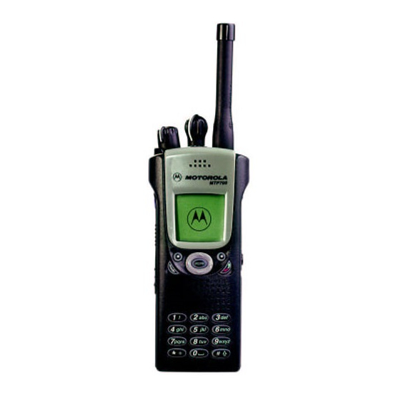
Motorola MTP700 Basic Service Manual
380 - 430 mhz/806 - 870 mhz
Hide thumbs
Also See for MTP700:
- Instruction booklet (4 pages) ,
- Detailed service manual (250 pages) ,
- Basic user's manual (60 pages)

Related Manuals for Motorola MTP700


Summary of Contents for Motorola MTP700
- Page 1 MTP700/MTP750 Digital Portable Radios 380 - 430 MHz 806 - 870 MHz Basic Service Manual Part Number: 6804113J98-O *6804113J98* March, 2004...
-
Page 2: Copyright
Motorola. Furthermore, the purchase of Motorola products shall not be deemed to grant, either directly or by implication, estoppel or otherwise, any license under the copyrights, patents or patent applications of Motorola, except for the normal non-exclusive royalty-free license to use that arises by operation of law in the sale of a product. -
Page 3: Document History
DOCUMENT HISTORY MTP700/MTP750 Portable Radios / Basic Service Manual DOCUMENT HISTORY The following major changes have been implemented in this manual since the previous edition: Edition Description Date 684113J98-O Initial edition Mar. 2004... - Page 4 MTP700/MTP750 Portable Radios / Basic Service Manual THIS PAGE INTENTIONALLY LEFT BLANK...
-
Page 5: Safety
RF exposure and helpful instructions on how to control your RF exposure. Your Motorola two-way radio is designed and tested to comply with a number of national and international standards and guidelines (listed below) regarding human exposure to radio frequency electromagnetic energy. - Page 6 MTP700/MTP750 Portable Radios / Basic Service Manual SAFETY Your Motorola two-way radio complies with the following RF energy exposure standards and guidelines: • United States Federal Communications Commission, Code of Federal Regulations; 47 CFR part 2 sub-part J • American National Standards Institute (ANSI) / Institute of Electrical and Electronic Engineers (IEEE) C95.
- Page 7 SAFETY MTP700/MTP750 Portable Radios / Basic Service Manual Facilities To avoid electromagnetic interference and/or compatibility conflicts, turn off your radio in any facility where posted notices instruct you to do so. Hospitals or health care facilities may be using equipment that is sensitive to external RF energy.
-
Page 8: Operational Warnings
MTP700/MTP750 Portable Radios / Basic Service Manual SAFETY Operational Warnings For Vehicles With An Air Bag Do not place a portable radio in the area over an air bag or in the air bag deployment area. Air bags inflate with great force. If a portable radio is placed in the air bag deployment area and the air bag inflates, the radio may be propelled with great force and cause serious injury to occupants of the vehicle. -
Page 9: Repair Of Fmrc Approved Products
• Do not disassemble an FMRC Approved Product in any way that exposes the internal circuits of the unit. Radios must ship from the Motorola manufacturing facility with the hazardous atmosphere capability and FM Approval labeling. Radios will not be “upgraded” to this capability and labeled in the field. A modification changes the unit’s hardware from its original design configuration. -
Page 10: Do Not Substitute Options Or Accessories
FMRC Approved model. Do Not Substitute Options or Accessories The Motorola communications equipment certified by Factory Mutual is tested as a system and consists of the FM Approved portable, FM Approved battery, and FM Approved accessories or options, or both. -
Page 11: Table Of Contents
CONTENTS MTP700/MTP750 Portable Radios / Basic Service Manual CONTENTS COPYRIGHT Computer Software Copyrights ....... . ii Trademarks . - Page 12 MTP700/MTP750 Portable Radios / Basic Service Manual CONTENTS CHAPTER 5 TEST SETUP & TESTING ......5-1 Typical Test Setup .
-
Page 13: Scope & Warranty Information
SCOPE & WARRANTY INFORMATION Scope Of This Manual This manual contains information necessary to identify and troubleshoot the MTP700/MTP750 Dim- etra Portable Radio at the board level. It also contains information on radio assembling, disassem- bling, and maintenance. Depending on the radio application, these radios are designed to work with Motorola’s Dimetra system or other TETRA compliant systems. -
Page 14: Warranty And Service Support
In instances where the product is covered under a "return for replacement" or "return for repair" war- ranty, a check of the product should be performed prior to shipping the unit back to Motorola. This is to ensure that the product has been correctly programmed or has not been subjected to damage outside the terms of the warranty. -
Page 15: European Radio Support Centers (Ersc)
Accessory Division (AAD). If no part number is assigned, the part is not normally available from Motorola. If a parts list is not included, this generally means that no user-serviceable parts are avail- able for that kit or assembly. -
Page 16: Asia Pacific Radio Support Centers
Aftermarket and Accessory Division (AAD). If no part number is assigned, the part is not normally available from Motorola. If a parts list is not included, this generally means that no user-serviceable parts are available for that kit or assembly. -
Page 17: Latin America Radio Support Centers
Aftermarket and Accessory Division (AAD). If no part number is assigned, the part is not normally available from Motorola. If a parts list is not included, this generally means that no user-serviceable parts are available for that kit or assembly. - Page 18 MTP700/MTP750 Portable Radios / Basic Service Manual THIS PAGE INTENTIONALLY LEFT BLANK...
-
Page 19: Model Information & Accessories
MODEL INFORMATION & ACCESSORIES MTP700/MTP750 Portable Radios/Basic Service Manual CHAPTER 2 MODEL INFORMATION & ACCESSORIES MTP700 Portable Radio Model Charts MTP700, 380-430 MHz Model Description H47QCM6TZ6AN MTP700 380-430 MHz 1W 25K CR PT911E *H47QCM6TZ6AB MTP700 380-430 MHz 1W 25K CR PT911E... - Page 20 MODEL INFORMATION & ACCESSORIES MTP700, 380-430 MHz (Continued) Model Description H47QCM6TZ6AN MTP700 380-430 MHz 1W 25K CR PT911E *H47QCM6TZ6AB MTP700 380-430 MHz 1W 25K CR PT911E H47QCM6TZ5AN MTP700 380-430 MHz 1W 25K ES PT911E *H47QCM6TZ5AB MTP700 380-430 MHz 1W 25K ES PT911E...
- Page 21 MODEL INFORMATION & ACCESSORIES MTP700/MTP750 Portable Radios/Basic Service Manual MTP700, 806-870 MHz Model Description H47XCM6TZ5AK MTP700 806-870 MHz 1W 25K ES PT711E (Korea) H47XCM6TZ6AN MTP700 806-870 MHz 1W 25K CR PT711E *H47XCM6TZ6AB MTP700 806-870 MHz 1W 25K CR PT711E H47XCM6TZ5AN...
- Page 22 MODEL INFORMATION & ACCESSORIES MTP700, 806-870 MHz (Continued) Model Description H47XCM6TZ5AK MTP700 806-870 MHz 1W 25K ES PT711E (Korea) H47XCM6TZ6AN MTP700 806-870 MHz 1W 25K CR PT711E *H47XCM6TZ6AB MTP700 806-870 MHz 1W 25K CR PT711E H47XCM6TZ5AN MTP700 806-870 MHz 1W 25K ES PT711E...
-
Page 23: Mtp750 Portable Radio Model Charts
MODEL INFORMATION & ACCESSORIES MTP700/MTP750 Portable Radios/Basic Service Manual MTP750 Portable Radio Model Charts MTP750, 380-430 MHz Model Description *H76QCM6TZ5AN MTP750 380-430 MHz 1W 25K ES PT911EE Item Description x **PMUE2128_ MTP750 Super Tanapa 380-430 MHz 1W 25K ES x **PMUE2129_... - Page 24 MTP700/MTP750 Portable Radios/Basic Service Manual MODEL INFORMATION & ACCESSORIES MTP750, 806-870 MHz Model Description *H76XCM6TZ5AN MTP750 806-870 MHz 1W 25K ES PT711EE Item Description x **PMUF1179_ MTP750 Super Tanapa 806-870 MHz 1W 25K ES x **PMUF1180_ MTP750 Super Tanapa 806-870 MHz 1W 25K ES (Chinese)
-
Page 25: Mtp700/Mtp750 Portable Radio Model Information
MTP700 380-430 MHz, 1 W, 25 kHz, with Continuous Rotary knob for group selection (CR) MTP700 & MTP750 380-430 MHz, 1 W, 25 kHz, with End Stop knob for group selection (ES) MTP700 806-870 MHz, 1 W, 25 kHz, with Continuous Rotary knob for group selection (CR) MTP700 &... -
Page 26: Mtp700/Mtp750 Portable Radio Model Specification
MTP700/MTP750 Portable Radios/Basic Service Manual MODEL INFORMATION & ACCESSORIES MTP700/MTP750 Portable Radio Model Specification GENERAL RECEIVER TRANSMITTER π /4 DQPSK ETSI: ETS 300 394-1 Receiver Type: Class B Modulation Type: Type Number (MPT700) Frequency Range: Nomin. Output Power: - 380-430 MHz:... -
Page 27: Mtp700/Mtp750 Accessories-To-Model Chart
MODEL INFORMATION & ACCESSORIES MTP700/MTP750 Portable Radios/Basic Service Manual MTP700/MTP750 Accessories-To-Model Chart MTP700/MTP750 PORTABLE RADIO 380-430 806-870 MHz ACCESSORIES Batteries - Smart Kit Number Battery, LiIon, Std, 1200 mAh PMNN4047_ Battery, NiMH, 1200 mAh PMNN4048_ Battery, NiMh, FM, 1150 mAh... - Page 28 2-10 MTP700/MTP750 Portable Radios/Basic Service Manual MODEL INFORMATION & ACCESSORIES MTP700/MTP750 PORTABLE RADIO 380-430 806-870 MHz ACCESSORIES Carrying Case Accessories Kit Number Hard leather case with Swivel PMLN4474_ Carrying strap for above NTN5243_ 2.5 inch belt clip HLN9714_ Light leather case ("GSM" style)
-
Page 29: Overview
This process is called digital modulation. Digital Modulation Technology The MTP700/MTP750 are 380-430 MHz or 806-870 MHz portable radios that can oper- ate in dispatch mode. They use two digital technologies: Π/4 DQPSK and Time Division Multiple Access (TDMA). - Page 30 MTP700/MTP750 Portable Radios / Basic Service Manual THIS PAGE INTENTIONALLY LEFT BLANK...
-
Page 31: Programming The Radio
PROGRAMMING THE RADIO MTP700/MTP750 Portable Radios / Basic Service Manual 4 - 1 CHAPTER 4 PROGRAMMING THE RADIO Before Using the Customer Programming Software (CPS) Before you begin programming, ensure the following: 1. Install the Customer Programming Software (CPS), FVN5051A, in your computer. -
Page 32: Reading Codeplug
4 - 2 MTP700/MTP750 Portable Radios /Basic Service Manual PROGRAMMING THE RADIO Reading Codeplug 1. Run the Customer Programming Software (CPS) on your computer. 2. Click the Toolbar “Read Phone” icon. Refer to the CPS Application Window Screen in the CPS User Guide, Publication No. 68P02956C20. The setup enters an initializa- tion process that takes about 20 seconds. -
Page 33: Programming Frequency
PROGRAMMING THE RADIO MTP700/MTP750 Portable Radios / Basic Service Manual 4 - 3 Programming Frequency Carry out the following steps if you need to add or change the radio frequencies. Note: Save your radio factory frequencies before you start programming by using “File”, “Save As”. -
Page 34: Restoring Factory Frequencies Of The Radio
4 - 4 MTP700/MTP750 Portable Radios /Basic Service Manual PROGRAMMING THE RADIO Restoring Factory Frequencies of the Radio To restore the factory frequencies of the radio, perform the following steps: 1. After testing your radio on the IFR, connect the setup as shown in Figure 4-1. -
Page 35: Manual Mode Testing
3. Press any key consecutively. The display shows vertical lines that becomes thicker with every key press, until it becomes fully dark. 4. Press any key again. The display shows the Motorola logo. 5. Press any key again. The display shows “Vibrator On”. - Page 36 4 - 6 MTP700/MTP750 Portable Radios /Basic Service Manual PROGRAMMING THE RADIO 10. Press any key again. The display shows “Speaker Tone Test”, a tone is heard via the speaker. 11. Press any key again. The display shows “Earpiece Tone Test”, a tone is heard via the earpiece.
-
Page 37: Test Setup & Testing
Any level 3 repairs can deeply affect the performance of the radio and may cause a new tuning procedure. This tuning procedure can only be applied by cerain authorised Motorola depots where the appropriate TEST & TUNE EQUIPMENT is available. -
Page 38: Test Equipment
MTP700/MTP750 Portable Radios / Basic Service Manual TEST SETUP & TESTING Test Equipment The table below lists the special test equipment required for servicing TETRA Portable Radios. Motorola Part No. Description WADN4161A* TETRA SERVICE MONITOR, MOBILES ONLY WADN4163A TETRA SERVICE MONITOR, MOBILES AND DIRECT MODE... -
Page 39: Test Check List
TEST SETUP & TESTING MTP700/MTP750 Portable Radios / Basic Service Manual Test Check List The following table summarises the required test setups. Note: Values for 380-430 MHz radio in brackets [ ]. Test Name Test Setup Radio Setup Test Conditions... - Page 40 MTP700/MTP750 Portable Radios / Basic Service Manual TEST SETUP & TESTING Test Name Test Setup Radio Setup Test Conditions Limits Digital Duplex RF Gen Level Private/Phone -90dBm Test (Tx) Mode 4 digit random number & “Send” Burst Power 28-31.5dBm Timing Error <=0.25 Symbols...
-
Page 41: How To Configure The Ifr 2968 System Setup
TEST SETUP & TESTING MTP700/MTP750 Portable Radios / Basic Service Manual How to Configure the IFR 2968 System Setup The setup depends on the firmware version of the IFR2968, the firmware version of the radio and the customer programming of the radio.The following steps should be taken only as an example of how to proceed for setup. - Page 42 MTP700/MTP750 Portable Radios / Basic Service Manual TEST SETUP & TESTING 19. Verify that the following values are displayed: POWER ON REGISTRATION: REQUIRED POWER OFF DE-REGISTRATION: REQUIRED PRIORITY CELL: MINIMUM MODE SERVICE: NEVER USED MIGRATION: SUPPORTED SYSTEM WIDE SERVICE: NORMAL MODE...
-
Page 43: How To Configure The Ifr 2968 Manual Test Screen
TEST SETUP & TESTING MTP700/MTP750 Portable Radios / Basic Service Manual 29. Press “Signal Type” soft key and “Direct set –up” soft key. 30. Press “Priority” soft key. Thereafter, enter “00” and press the “Priority” soft key. 31. Leave “Calling Party SSI” setting to default value. -
Page 44: Rf Tests
MTP700/MTP750 Portable Radios / Basic Service Manual TEST SETUP & TESTING RF Tests Test Page 1. To set the radio into Test Page, perform the following sequence (feature must be turned on in CPS i.e. “User Personal Data\Ergonomic Parameters\Feature Flags\Test Page” checked on). When performing steps 2 thru 5, make sure that you press the handset keys sequentially (less than a second between every consecutive press). - Page 45 TEST SETUP & TESTING MTP700/MTP750 Portable Radios / Basic Service Manual Note: “00000100” is the programmed Radio SSI. 6. In the event registration is unsuccessful, turn the radio OFF then ON again. RSSI Test Before carrying out the following steps, record the Insertion loss (dB) of the cable loss value (denote as X dB).
-
Page 46: Transmitter Tests
5-10 MTP700/MTP750 Portable Radios / Basic Service Manual TEST SETUP & TESTING Transmitter Tests 1. Change the “Mode” key of the radio to “Group Mode”. 2. Press the “RF Gen Level” soft key and enter “-90dBm”. 3. Press and hold the radio PTT and monitor the IFR “Manual Test” screen which dis- plays the Power Profile, Burst Power, Timing Error, Frequency Error and Vector Error. -
Page 47: Duplex Test (Phone/Private Mode)
TEST SETUP & TESTING MTP700/MTP750 Portable Radios / Basic Service Manual 5-11 Call to Mobile 1. Press the radio “Mode” key and change to “Private” mode. 2. Press the “RF Gen Level” soft key and enter “-90dBm”. 3. Press the “Call Mobile” soft key and select “Private Call” on the IFR. Verify that four beeps are heard from the speaker. - Page 48 5-12 MTP700/MTP750 Portable Radios / Basic Service Manual TEST SETUP & TESTING For Power Analyser Graph: 5. Press “power ana” soft key (the same button changes to “Bar Charts” soft key). 6. Check that the power frame falls within the limits.
-
Page 49: Dmo Test
TEST SETUP & TESTING MTP700/MTP750 Portable Radios / Basic Service Manual 5-13 DMO Test IFR 2968 Test Setup Note: Terms for 380-430 MHz radio in brackets [ ]. 1. Press the “System” soft key. 2. Press “TETRA Direct” soft key. -
Page 50: Rf Test - Transmit Test
5-14 MTP700/MTP750 Portable Radios / Basic Service Manual TEST SETUP & TESTING RF Test - Transmit Test Hold the PTT in the pressed position long enough to enable you to read the results: • Results: - Power Profile: Passed. •... -
Page 51: Service Flow Chart
TEST SETUP & TESTING MTP700/MTP750 Portable Radios / Basic Service Manual 5-15 Service Flow Chart Connect the radio to the IFR (1) Fail Pass Perform all Maintenance tests: RF and audio level? Fail - Replace the customer’s radio Replace - Send the faulty radio to Level 3 maintenance... - Page 52 5-16 MTP700/MTP750 Portable Radios / Basic Service Manual THIS PAGE INTENTIONALLY LEFT BLANK...
-
Page 53: Maintenance
MAINTENANCE MTP700/MTP750 Portable Radios / Basic Service Manual 6 - 1 CHAPTER 6 MAINTENANCE Introduction This chapter provides details about the following: • Preventive Maintenance (inspection and cleaning) • Safe Handling of CMOS and LDMOS Devices • Repair Procedures and Techniques •... - Page 54 6 - 2 MTP700/MTP750 Portable Radios / Basic Service Manual MAINTENANCE Cleaning External Plastic Surfaces Apply the 0.5% detergent-water solution sparingly with a stiff, non-metallic, short-bristled brush to work all loose dirt away from the radio. Use a soft, absorbent, lintless cloth or tis- sue to remove the solution and dry the radio.
-
Page 55: Safe Handling Of Cmos And Ldmos Devices
• Ground the working surface of the service bench to protect the CMOS device. We recommend using the Motorola Static Protection Assembly (part number 0180386A82), which includes a wrist strap, two ground cords, a table mat, and a floor mat. -
Page 56: Repair Procedures And Techniques - General
When damaged parts are replaced, identical parts should be used. If the identical replacement part is not locally available, check the parts list for the proper Motorola part number and order the part from the nearest Motorola Radio Support Center. For details, please refer to relevant Support Depots on page 1-3 to 1-5. -
Page 57: Radio Disassembly - Detailed
MAINTENANCE MTP700/MTP750 Portable Radios / Basic Service Manual 6 - 5 Radio Disassembly - Detailed Front Cover from Chassis Disassembly 1. Turn off the radio. 2. Remove the battery: a. Pull down on the two battery-release buttons. b. With the buttons pulled down, the top of the battery will fall from the radio. - Page 58 6 - 6 MTP700/MTP750 Portable Radios / Basic Service Manual MAINTENANCE 4. Remove the Talkgroup knob off its shaft. Talkgroup Knob Figure 6-2 Talkgroup Knob Removal NOTE The knob slides on and off. However, it is supposed to fit very tightly on its shaft.
- Page 59 MAINTENANCE MTP700/MTP750 Portable Radios / Basic Service Manual 6 - 7 6. Push the Talkgroup switch shaft back into radio housing to slide chassis away. 7. Gently remove flex from the socket connector. 8. Lay the chassis down. Rotate the front cover backward and slightly away from the chassis.
-
Page 60: Chassis Assembly Disassembly
6 - 8 MTP700/MTP750 Portable Radios / Basic Service Manual MAINTENANCE Chassis Assembly Disassembly 1. Use a TORX™ screwdriver with a T6 head to remove the five screws holding the secondary shield and main board to the chassis. Secondary Shield... -
Page 61: Radio Reassembly - Detailed
MAINTENANCE MTP700/MTP750 Portable Radios / Basic Service Manual 6 - 9 Radio Reassembly - Detailed Chassis Assembly Reassembly 1. Reassemble the O-ring. The tabs on the O-ring should reach around the chassis and point down. 2. Place the eight small O-ring retainers into their slots in the chassis. - Page 62 6 - 10 MTP700/MTP750 Portable Radios / Basic Service Manual MAINTENANCE 10. Turn on the Volume knob and make sure radio powers up normally. Radio Chassis Figure 6-6 Fastening the Chassis...
-
Page 63: Service Aids
The following table lists the service aids recommended for working on the radio. While all of these items are available from Motorola, most are standard workshop equipment items and any equivalent item capable of the same performance may be substituted for the item listed. -
Page 64: Mtp700/Mtp750 Unit - Exploded View
6 - 12 MTP700/MTP750 Portable Radios / Basic Service Manual MAINTENANCE MTP700/MTP750 Unit - Exploded View Figure 6-7 MTP700/MTP750 - Exploded view... - Page 65 MTP700/MTP750 Portable Radios / Basic Service Manual 6 - 13 MTP700/MTP750 components are listed in the table below. The first column marked with a # sign provides you with the call out numbers of the components as marked in MTP700/MTP750 - Exploded view.
- Page 66 6 - 14 MTP700/MTP750 Portable Radios / Basic Service Manual THIS PAGE INTENTIONALLY LEFT BLANK...
-
Page 67: Servicing Mtp700/Mtp750 Portable Units
For details, please refer to relevant Support Depots on page 1-3 to 1-5. Level 3 Maintenance The level 3 maintenance can only be done at the factory. Contact your local Motorola CGISS for information. Replacement Parts Damaged parts should be replaced with identical replacement parts. For complete infor- mation on ordering required parts and kits, contact your local customer service represent- ative. -
Page 68: Service Kits
MTP700, 806-870 MHz, 1W, 25kHz, with Continuous Rotary knob for group selection (CR) MTP700, 806-870 MHz, 1W, 25kHz, with End Stop knob for group selection (ES) MTP700, 806-870 MHz, 1W, 25kHz, with End Stop knob for group selection (ES), Ko- rean Model... - Page 69 A - 3 MTP700 Model Description MTP700, 380-430 MHz, 1W, 25kHz, with Continuous Rotary knob for group selection (CR) MTP700, 380-430 MHz, 1W, 25kHz, with End Stop knob for group selection (ES) MTP700, 806-870 MHz, 1W, 25kHz, with Continuous Rotary knob for group selection (CR)
- Page 70 A - 4 MTP700/MTP750 Portable Radios / Basic Service Manual REPLACEMENT PARTS AND KITS MTP750 Model Description MTP750, 380-430 MHz, 1W, 25kHz, with End Stop knob for group selection (ES) MTP750, 806-870 MHz, 1W, 25kHz, with End Stop knob for group selection (ES)
-
Page 71: General
CONNECTOR PIN FUNCTIONS MTP700/MTP750 Portable Radios / Basic Service Manual B - 1 APPENDIX B CONNECTOR PIN FUNCTIONS General This appendix describes the connector pin functions for the Radio. The description gives information on the type of signals, voltages and current conditions. Pins which are... - Page 72 B - 2 MTP700/MTP750 Portable Radios / Basic Service Manual CONNECTOR PIN FUNCTIONS Name Function Description EXT_SPEAKER+ Speaker + (pin 1) and Speaker - (pin 2) are used for the external speaker. Typical output power is 0.5W for a 20 ohm load.
-
Page 73: Bottom Accessory Connector Pin Assignment
CONNECTOR PIN FUNCTIONS MTP700/MTP750 Portable Radios / Basic Service Manual B - 3 Bottom Accessory Connector Pin Assignment 1 1 1 1 1 1 1 1 1 1 1 1 Headset Indication / Key_Fail On_Off/JTAG / Flash Mode Bottom_Option_2 Bottom_Option_1... - Page 74 B - 4 MTP700/MTP750 Portable Radios / Basic Service Manual CONNECTOR PIN FUNCTIONS Name Function Description POWER GROUND IN/OUT Used as ground. USB+/TXD (D+)/TDO IN/OUT +ve signal for the USB bus/transmit data in RS-232 mode/serial output in JTAG Mode. USB-/RXD (D-)/TDI...