Advertisement
Quick Links
This manual only describes the specifications for Display Module FX
For complete operation, wiring, mounting and programming instructions please refer to the FX
HARDWARE MANUAL and PROGRAMMING MANUAL.
These manuals should be read and understood before attempting to install or use the unit.
Related Manuals
Manual name
FX
Series Hardware
1S
Manual
FX
Series Hardware
1N
Manual
FX Series
Programming Manual II
1. Outline of Product
1.1 Features
The micro display module FX
mounted on the top face of the FX
can monitor/update internal PLC data.
PLCs installed to: FX
1.2 Product configuration
Main unit
: FX
-5DM
1N
Accessories : Top cover for DM 1,
1.3 Outside dimensions
17(0.67)
11(0.43)
40(1.57)
-
+
ESC
OK
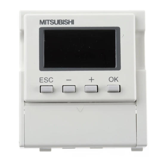
1.4 Name of each part
➄
-
+
ESC
OK
➀ ➁ ➂ ➃
➆
Manual No.
JY992D83901
JY992D88201
JY992D88101
-5DM (hereafter referred to as "5DM") is
1N
/FX
1S
1N
and FX
Series
1S
1N
M3 screw to mount top cover 1
4.6
(0.18)
➀
ESC key: Cancels the last key operation or returns to the previous screen.
➁
"-" key: Scrolls the device No. to a smaller one or decrements a numeric
value by.
➂
"+" key: Scrolls the device No. to a larger one or increments a numeric
value.
➃
OK key: Determines the display device, executes write of a numeric value,
➅
or changes over forced setting and forced resetting.
➄
Display area: Displays the current time and the monitored device status.
➅
Connector for PLC
➆
5DM mounting hook
DISPLAY MODULE FX
USER'S MANUAL
Describes contents related to hardware of FX
PLC such as specifications, wiring and installation.
(It is offered with FX
Describes contents related to hardware of FX
PLC such as specifications, wiring and installation.
(It is offered with FX
Describes instructions in FX
Series PLC basic unit and
When installed to a PLC
2
40
(0.07)
(1.57)
9
26
(0.35)
(1.03)
10
8
8
8
(0.39)
(0.31)
(0.31)
(0.31)
Unit: mm (inches)
Outer painting color: Munsell 0.08GY/7.64/0.81
Mass: 20 g (0.05 lbs)
-5DM
1N
JY992D84901E
-5DM.
1N
Description
Series PLC basic unit.)
1S
Series PLC basic unit.)
1N
/FX
/FX
1S
1N
2N
AC85
- 264V
FX
-5DM
1N
Note: These dimensions
FX
Series
1S
FX
Series
1N
, FX
1S
1N
Series
1S
Series
1N
/FX
Series.
2NC
COM
X1
X3
X5
L
X0
X2
X4
N
0 1 2 3
4
5
IN
POWER
-
+
ESC
OK
RUN
ERROR
FX
-10MR
1S
OUT
0 1 2 3
COM
Y0
Y1
Y2
Y3
10MR
24+
COM0
COM1
COM2
COM3
measured
from the left side
are common
to the FX
and
1S
FX
Series.
1N
Advertisement

Related Manuals for Mitsubishi FX1N-5DM


Summary of Contents for Mitsubishi FX1N-5DM
- Page 1 DISPLAY MODULE FX -5DM USER’S MANUAL JY992D84901E This manual only describes the specifications for Display Module FX -5DM. For complete operation, wiring, mounting and programming instructions please refer to the FX , FX HARDWARE MANUAL and PROGRAMMING MANUAL. These manuals should be read and understood before attempting to install or use the unit. Related Manuals Manual name Manual No.
-
Page 2: Installation
2. Installation Install the 5DM to the PLC using the following procedure. A) Top cover for DM (offered as an accessory of 5DM) B) Connector for optional equipment C) M3 screw to fix top cover • Remove the top cover of the basic unit, and attach the top cover for DM A) instead. - Page 3 Cautions: 1) If a keyword to prohibit read, write or read and write of programs is registered in the PLC, only the clock time display function is available. Any other function shown above is not available. If any operation is performed in the 5DM when a keyword is registered in the PLC, the error display flickers for 5 seconds.
-
Page 4: Operation List
-5DM please consult the nearest Mitsubishi Electric distributor. • Under no circumstances will Mitsubishi Electric be liable or responsible for any consequential damage that may arise as a result of the installation or use of this equipment. • All examples and diagrams shown in this manual are intended only as an aid to understanding the text, not to guarantee operation. Mitsubishi Electric will accept no responsibility for actual use of the product based on these illustrative examples. - Page 5 This manual confers no industrial property rights or any rights of any other kind, nor does it confer any patent licenses. Mitsubishi Electric Corporation HEAD OFFICE : TOKYO BUILDING, 2-7-3 MARUNOUCHI, CHIYODA-KU, TOKYO 100-8310 JAPAN cannot be held responsible for any...
- Page 6 Cautions: 2. Installation 1) If a keyword to prohibit read, write or read and write of programs is registered in the PLC, only the clock time display function is available. Any other function shown above is not available. Install the 5DM to the PLC using the following procedure. If any operation is performed in the 5DM when a keyword is registered in the PLC, the error display A) Top cover for DM (offered as an accessory of 5DM) flickers for 5 seconds.
- Page 7 HIMEJI WORKS : 840, CHIYODA CHO, HIMEJI, JAPAN • Under no circumstances will Mitsubishi Electric be liable or responsible for any consequential damage that may arise as a result of the installation or use of this equipment. problems involving industrial property •...