Advertisement
Quick Links
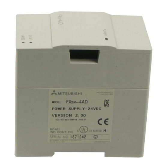
This manual contains text, diagrams and explanations which will guide the reader in the correct installation and
operation of the FX
-4AD and should be read and understood before attempting to install or use the unit.
2N
Further information can be found in the FX SERIES PROGRAMMING MANUAL, FX
1
•
The FX
-4AD analog special function block has four input channels. The input channels receive analog signals
2N
and convert them into a digital value. This is called an A/D conversion. The FX
12 bits.
•
The selection of voltage or current based input/output is by user wiring. Analog ranges of -10 to 10V DC (resolution:
5mV), and/or 4 to 20mA, -20 to 20mA(resolution: 20µA) may be selected.
•
Data transfer between the FX
memories (each of 16 bits) in the FX
•
The FX
-4AD occupies 8 points of I/O on the FX
2N
or outputs. The FX
2N
1.1 EXTERNAL DIMENSIONS
2
Voltage input
-10V to +10V
CH4
2
1
Shielded
Current input
-20mA to +20mA
CH1
3
1
Shielded
4
DC24V 55mA
5
Class 3
PC
Grounding
(100Wor less)
Extension cable
-4AD and the FX
2N
-4AD.
2N
-4AD draws 30mA from the 5V rail of the FX
Weight : Approx. 0.3 kg (0.66 lbs)
TERMINAL LAYOUTS
100KW
V +
250W
CH4
I +
VI-
100KW
F G
AG
100KW
V +
250W
CH1
I +
VI-
100KW
F G
+15V
24+
DC/DC
AG
converter
24-
-15V
FX
-4AD
2N
Analog Input Block
FX
-4AD SPECIAL FUNCTION BLOCK
2N
INTRODUCTION
main unit is by buffer memory exchange. There are 32 buffer
2N
expansion bus. The 8 points can be allocated from either inputs
2N
main unit or powered extension unit.
2N
The analog input is received through a twisted pair
shielded cable. This cable should be wired separately
from power lines or any other lines which may induce
electrical noise.
If a voltage ripple occurs during input, or there is
electrically induced noise on the external wiring, connect a
smoothing capacitor of 0.1 to 0.47µF, 25V.
If you are using current input, connect the V+ and I+
terminals to each other.
If there is excessive electrical noise, connect the FG frame
ground terminal with the grounded terminal on the
FX
-4AD.
2N
Connect the ground terminal on the FX
grounded terminal on the main unit. Use class 3
grounding on the main unit, if available.
USER'S GUIDE
JY992D65201A
SERIES HARDWARE MANUAL .
2N
-4AD has maximum resolution of
2N
Dimensions : mm (inches)
-4AD unit with the
2N
Advertisement

Summary of Contents for Mitsubishi MELSEC-F FX2N Series
- Page 1 -4AD SPECIAL FUNCTION BLOCK USER’S GUIDE JY992D65201A This manual contains text, diagrams and explanations which will guide the reader in the correct installation and operation of the FX -4AD and should be read and understood before attempting to install or use the unit. Further information can be found in the FX SERIES PROGRAMMING MANUAL, FX SERIES HARDWARE MANUAL .
- Page 2 INSTALLATION NOTES AND USAGE 3.1 Environment specification Item Specification Environmental specifications (excluding following) Same as those for the FX main unit Dielectric withstand voltage 500VAC, 1min (between all terminals and ground) 3.2 Power supply specification Item Specification 24V DC ± 10%, 55mA Analog circuits (external power supply from main unit) Digital circuits...
- Page 3 3.4 Allocation of buffer memories (BFM) In buffer memory locations (BFMs) Contents marked with an “*” data can be written Channel initialization Default = H0000 from the PC using the TO command. Channel 1 Contains the number of samples (1 to 4096) to be used for an averaged result.
- Page 4 (4) Status Information BFM #29 Bit devices of BFM #29 When any of b1 to b4 is ON. b0 : Error If any of b2 to b4 is ON, A/D conversion of No error all the channels is stopped Offset/Gain data in EEPROM is corrupted b1 : Offset / gain error Offset/Gain data normal or adjustment error.
- Page 5 EXAMPLE PROGRAM 5.1 Basic Program In the following example channels CH1 and CH2 are used as voltage inputs. The FX -4AD block is connected at the position of special function block No.0. Averaging is set at 4 and data registers D0 and D1 of the PC receive the averaged digital data.
- Page 6 -4AD please consult the nearest Mitsubishi Electric distributor. • Under no circumstances will Mitsubishi Electric be liable or responsible for any consequential damage that may arise as a result of the installation or use of this equipment. • All examples and diagrams shown in this manual are intended only as an aid to understanding the text, not to guarantee operation.
- Page 7 3.4 Allocation of buffer memories (BFM) INSTALLATION NOTES AND USAGE In buffer memory locations (BFMs) Contents 3.1 Environment specification marked with an “*” data can be written Channel initialization Default = H0000 from the PC using the TO command. Channel 1 Contains the number of samples (1 to Item Specification...
- Page 8 -4AD please consult the nearest Mitsubishi Electric distributor. Digital • Under no circumstances will Mitsubishi Electric be liable or responsible for any consequential damage that may arise as a result of the installation or use of this equipment. Offset value X010 Adjustment start.


