
Related Manuals for Endress+Hauser FMX 570


Summary of Contents for Endress+Hauser FMX 570
- Page 1 BA 119F/00/en/06.03 silometer 016338-1000 Software Version 1.x FMX 570 Level Measurement Operating Instructions FMX 570 Endress Hauser The Power of Know How...
-
Page 2: Measurement At A Glance
Silometer FMX 570 Measurement at a Glance Level Measurement at a Glance Function Matrix Action Enter 671: »+« and »-« keys, ⇒ changes digit 1 Reset transmitter V9H5 Press »E« to register entry Omit if commissioned as in Section 4.1 2 »Empty«... - Page 3 Measurement at a Glance Silometer FMX 570 Silometer FMX 570 Selects vertical matrix position Selects horizontal matrix position Matrix position FMX 570 Select position V0H0 Measured value Selects next digit Bar chart Move decimal point Matrix selection Increases value of digit...
-
Page 4: Table Of Contents
Sensor connection ... . 13 Technical data: Silometer FMX 570 transmitter . 14 Index .... -
Page 5: Notes On Safety
Notes on Safety Notes on Safety The Silometer FMX 570 is a level measurement transmitter which can be used with a variety of probes and sensors. It must be installed by qualified personnel according to the instructions in this manual. - Page 6 Notes on Safety Silometer FMX 570 Safety conventions In order to highlight safety-relevant or alternate operation procedures in the manual the following conventions have been used, each indicated by a corresponding icon in the margin. Note! • A note highlights actions or procedures which, if not performed correctly, may indirectly affect operation or may lead to an instrument response which is not planned.
-
Page 7: Introduction
The front cover contains short instructions for continuous level measurement with the Quick Operating Guides default parameters. Users unfamiliar with the Silometer FMX 570 must read the operating instructions, which In this manual are structured as follows: • Chapter 1: Introduction;... -
Page 8: Application
The capacitance or pressure measured by the sensor is converted into a frequency signal by the electronic insert located in its head. The Silometer FMX 570 supplies the power and receives a level-proportional frequency signal over a two-core cable. The signal is then processed to provide a level or volume measurement. -
Page 9: Measuring Principle
Chapter 1: Introduction Measuring principle The Silometer FMX 570 measures level on the basis of the capacitance and hydrostatic measurement principles. In both cases the measured value is processed by the electronic insert and passed on as a frequency signal. -
Page 10: Installation
Probes and sensors Table 2.1 lists the probes most frequently used with the Silometer FMX 570 transmitter. In addition to those listed, all probes which can be used with an EC 37 Z or EC 47 Z electronic insert can be connected to the transmitter. Installation hints can be taken from the appropriate Technical Information Sheet. -
Page 11: Silometer Installation
Chapter 2: Installation Silometer FMX 570 Silometer installation There are three possibilities for installing Silometer transmitters: • Standard 19" rack with space for 12 7HP cards, • Field housing with space for up to 6 7HP cards, • Monorack housings for single transmitters. - Page 12 Full details of the Monorack installation procedure can be taken from the manual supplied with it. Monorack protective If the Silometer FMX 570 transmitter and Monorack housing are to be mounted at an housing exposed site, then it is recommended that they be installed in the protective housing, degree of protection IP 55, which is available as an accessory.
-
Page 13: Transmitter Wiring
• Two indexing pins, at positions 2 and 9 in the rack connector ensure that Silometer FMX 570 transmitters only can be inserted at these points. The pins must be inserted if the rack is not custom built by Endress+Hauser. - Page 14 • Insert the coding pins supplied at positions 2 and 9 in the female connector at the base of the housing. • The pin assignments printed in black are valid for the Silometer FMX 570. Note! If you are installing the Silometer FMX in a Monorack I housing, please note that there is no jumper switch.
-
Page 15: Sensor Connection
Chapter 2: Installation Silometer FMX 570 Sensor connection The Silometer FMX 570 can be operated with a variety of sensor types, each requiring a different electronic insert, e.g.: • EC 37 Z or EC 47 Z for capacitance and Multicap probes •... -
Page 16: Technical Data: Silometer Fmx 570 Transmitter
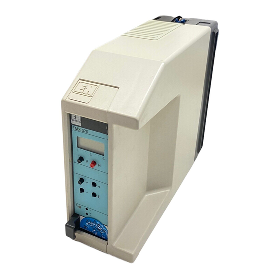
Silometer FMX 570 Chapter 2: Installation Technical data: Silometer FMX 570 transmitter Fig. 2.8 Silometer FMX 570 plug-in card BA119E22 • Design: Construction 19", 7 HP, plug-in card • Front panel: black synthetic with blue field inlay, grip and markings, Protection: IP 20 (DIN 40050) •... -
Page 17: Controls
Fig. 3.1: • Each field in the matrix is accessed by a vertical (V) and horizontal (H) position which can be entered at the front panel of the FMX 570 with the V and H keys •... -
Page 18: Configuration And Display
BA119E23 Fig. 3.1 shows the LC-display with matrix of the Silometer FMX 570, Fig. 3.2 its front panel. Table 3.1 below describes the function of the operating keys. • Changes are not possible if the matrix has been locked (Section 4.7). -
Page 19: Calibration And Operation
Chapter 4: Calibration and Operation Silometer FMX 570 Calibration and Operation This chapter is concerned with the basic settings of the Silometer FMX 570 which allow it to operate for continuous level measurement. The principle sections describe: • Commissioning • Calibration for level measurement •... -
Page 20: Calibration For Level Measurement
If the level is entered in m, ft. etc. the analogue outputs must be set in the same units, see Chapter 6. Fig. 4.1: Parameters required for Capacitance probe Capacitance probe calibration of the Silometer FMX 570 for level measurement shown for bulk solid measurement. Any filling mound or outflow »Full« V0H2 depression can be accounted for e.g. -
Page 21: Calibration For Linear Volume Or Weight Measurement
Deltapilot S BA119Y28 The Silometer FMX 570 can also be calibrated in volume or weight units, e.g. in litres, hectolitres, gallons, %vol, tonnes or kg. After calibration volume (or weight) is displayed at V0H0. The analogue output must be set in the same units, as described in Chapter 6. -
Page 22: Dry Calibration« For Open Vessels
It may not always be possible to fill and empty the vessel for the calibrations as described in Sections 4.2 and 4.3. To cover this eventuality the Silometer FMX 570 can be calibrated »dry« by using the sensor constants. For this alternative calibration you need: •... - Page 23 Chapter 4: Calibration and Operation Silometer FMX 570 The entry of values in V3H5/V3H6 adapts Offset and sensitivity of Probe sensitivity ∆F, P/mbar the Silometer to the application. It now the display, V3H1/V3H2 V3H6 level knows which pressure is associated with a particular frequency.
-
Page 24: Level Offset Value
Silometer FMX 570 Chapter 4: Calibration and Operation Level offset value Fig. 4.5: Effect of level offset on display at V0H0 for level measurement without linearization After offset = -250 Before offset Volume 250 m Volume 250 m Display 250 m Display 0.000... -
Page 25: Measured Value Display
Chapter 4: Calibration and Operation Silometer FMX 570 Measured value display During normal operation the measured value can be read at V0H0 In addition to this, several other fields contain system information which might be needed, e.g., for trouble-shooting. Table 4.1 summarizes the measured value displays. -
Page 26: Linearization
Chapter 5: Linearization Silometer FMX 570 Linearization Fig. 5.1: Linearization for a vessel with a 30.00 133.0 conical outlet »Full« = 90% »Full« = 500 hl »Empty« = 10% »Empty« = 35 hl 7.000 120.0 »Full« = 9 ft »Full« = 150 gal »Empty«... -
Page 27: Linearization For A Horizontal Cylindrical Tank
BA119Y41 Use this mode if you have a cylindrical tank which lies horizontally. The Silometer FMX 570 transmitter uses a stored linearization table which requires the entry of the tank diameter, tank volume for its volume calculations. Procedure... -
Page 28: Linearization For A Tank With Conical Outlet
Chapter 5: Linearization Silometer FMX 570 Linearization for a tank with conical outlet Fig. 5.3: Linearization for a vessel with a conical outlet level (m) V0H9 Max. level = 4.75 m »Full« = 4.25 m 0.5 m 1.0 m »Empty« = 1m 1.5 m... - Page 29 Silometer FMX 570 Chapter 5: Linearization Manual linearization Volume Level Volume Level with tabular values V2H2 V2H3 V2H4 V2H2 V2H3 V2H4 Procedure Step Matrix Entry Significance V9H5 e.g. 672 Reset transmitter (default = operating mode 1) Enter sensor constants at V3H5 and V3H6 »E«...
- Page 30 Chapter 5: Linearization Silometer FMX 570 Manual linearization with Step Matrix Entry Significance automatic level V9H5 e.g. 672 Reset transmitter (default = operating mode 1) registration Enter sensor constants at V3H5 and V3H6 »E« Register entry V0H1/V0H2 - Calibrate as described in e.g Section 4.2...
-
Page 31: Other Modes
Silometer FMX 570 Chapter 5: Linearization Other modes This mode (default) is selected when the Silometer FMX 570 transmitter is to revert to Linear measurement of level after being used for volume measurement. V2H0 = 0 • If the volume is proportional to level, e.g. standing cylinder, a volume measurement is obtained by entering the »empty«... -
Page 32: Analogue Outputs
V0H7 fail to -10 % BA119Y29 This Chapter deals with the analogue output settings. The FMX 570 transmitter is designed for continuous measurement with control of: • one voltage output 0/2 ... 10 V • one current output 0/4 ... 20 mA by the level or volume indication at V0H0. -
Page 33: Analogue Output Settings
Silometer FMX 570 Chapter 6: Analogue Outputs Analogue output settings One of two analogue ranges can be set at V0H3: Analogue output range • 0 = 0 ... 20 mA/ 0...10 V • 1 = 4 ... 20 mA/ 2...10 V (default setting.). - Page 34 Output at fault The current and voltage outputs can be set to take on distinctive values if the self- monitoring circuit of the Silometer FMX 570 transmitter triggers on finding a fault. The choice is made at V0H7, whereby: • 0 = -10% of full scale ≤...
-
Page 35: Trouble-Shooting
When the instructions in the manual have been followed correctly, the system must now function. Should this not be the case, the Silometer FMX 570 transmitter provides a number of aids for setting up and operating the module correctly. This Chapter contains the following: •... - Page 36 Silometer FMX 570 Chapter 7: Trouble-Shooting Table 7.1: Code Type Cause and Remedy Error messages E 101-106 Alarm Fault in instrument electronics - Call Endress+Hauser Service E 107 Alarm Battery voltage too low - Make back-up of entered parameters immediately...
-
Page 37: Simulated Operating Mode
Chapter 7: Trouble-Shooting Silometer FMX 570 Simulated operating mode This function is intended primarily for checking the correct function of the system and is selected and terminated at V8H0: • Enter 6 to simulate frequency, level, volume or current • Enter an operating mode to terminate simulation and resume normal measurements. -
Page 38: Exchanging Transmitters, Probes And Electronic Inserts
Electronic insert EC 37 Z/ EC 47 Z showing location of C(S)(pF) (pF) probe constants FMC 480 Z FMC 470 Z / FMX 570 d4 / z4 d2 / z2 FMC 671 / 672 / 676 / 677 Z HAA 420 Z 1 MHz... -
Page 39: Repairs
Remember that all probes are sensitive instruments and must be treated accordingly. Should the Silometer FMX 570 transmitter or its probes need to be repaired by Endress+Hauser, please send it to your nearest Service Centre with a note containing the following information: •... -
Page 40: Quick Programming Guide
Silometer FMX 570 Chapter 8: Quick programming guide Quick programming guide Level measurement Start Chapter 4, Section 4.1 Reset parameters: V9H5 - Constants for EC 37 Z/EC 47 Z or Enter sensor constants FEB 17 / FEB 17 P - Zero frequency... -
Page 41: Continuous Volume Measurement (Linearization)
Chapter 8: Quick programming guide Silometer FMX 570 Continuous volume measurement (linearization) Start Chapter 4, Section 4.1 Reset parameters: V9H5 - Constants for EC 37 Z/EC 47 Z or Enter sensor constants FEB 17 / FEB 17 P zero frequency... -
Page 42: Index
Silometer FMX 570 Index Index 0/4…20 mA signal Offset Operating matrix Operating mode Operating parameters Analogue outputs 11, 14, 30 - 32 Output at fault Analogue range Output damping Application Parameter matrix lock Calibration 18 - 19 Pin assignment »Dry« for Deltapilot... - Page 43 Silometer FMX 570 Operating matrix Operating Matrix Operating and default parameters Enter your operating parameters in the matrix below. Display field The default parameters are as indicated below. 100.0 100.0 10.0 1020 Display field...
- Page 44 Operating matrix Silometer FMX 570 Parameter Matrix Measured Empty Full Select Output Value for Value for Safety Actual Measured alarm value calibration calibration current damping 0/4 mA 20 mA measuring value Calibration 0 = -10% frequency 0=0…20mA before Channel 1...
- Page 48 Belorgsintez Canada Poland Singapore Minsk Endress+Hauser Ltd. Endress+Hauser Polska Sp. z o.o. Endress+Hauser (S.E.A.) Pte., Ltd. Tel. (01 72) 508473, Fax (01 72) 508583 Burlington, Ontario Warszawy Singapore Tel. (9 05) 6 81 92 92, Fax (9 05) 6 81 94 44 Tel.