Panasonic FP0-TC4 Technical Manual
Programmable controller
Hide thumbs
Also See for FP0-TC4:
- Specifications (21 pages) ,
- Specifications (25 pages) ,
- Specifications (27 pages)
Table of Contents
Advertisement
Advertisement
Table of Contents

Related Manuals for Panasonic FP0-TC4


Summary of Contents for Panasonic FP0-TC4
- Page 2 -This manual and its contents are copyrighted. -You may not copy this manual, in whole or part, without written consent of Panasonic Electric Works SUNX Co., Ltd. -Windows is a registered trademark of Microsoft Corporation in the United States and other countries.
-
Page 3: Table Of Contents
Table of Contents Precautions before Usage 1 Unit Outlines..........................1 1.1 Functions ..............................1 1.2 Model ................................1 1.3 Unit Connection Limit ..........................1 2 Part Names and Functions......................2 3 Input Range Setting Switch ......................3 4 Wiring............................4 5 Conversion Characteristic ...................... -
Page 4: Precautions Before Usage
Precautions before Usage - Accuracy ・ Connecting/disconnecting the Thermocouple input terminal block while the Thermocouple Unit is ON will lower an accuracy temporarily. Accordingly, use the temperature data obtained 15 minutes after its action. ・ When a high-accurate temperature data is required, use the temperature data obtained 15 minutes after turning ON the Thermocouple Unit. -
Page 5: Unit Outlines
6. The broken-thermocouple detector is attached. A thermocouple, broken, can be detected. 1.2 Model - Thermocouple Unit Thermocouple Part number Product number input points FP0-TC4 4 points AFP0420 FP0-TC8 8 points AFP0421 1.3 Unit Connection Limit - Number limit Up to 3 expansion units can be connected with the Control Unit. -
Page 6: Part Names And Functions
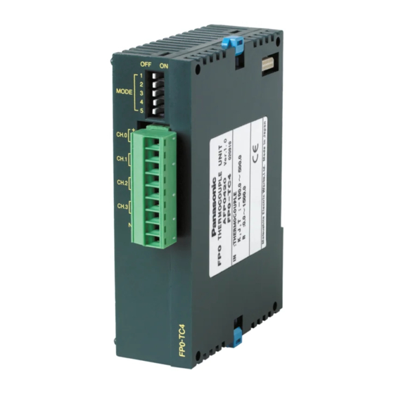
2 Part Names and Functions - Thermocouple Unit ①Input range setting switch changes between the input ranges (thermocouple types). Only the same range setting is available for all the 8 channels. (The setting can not be specified per channel.) Reference: “4 Input Range Setting Switch”. ②Thermocouple input terminal block (9-pin) is made by Phoenix. -
Page 7: Input Range Setting Switch
2) Temperature unit switch MODE SW ℃ ℉ Unit 3) Input channel selection switch MODE SW Input channel CH0, 1 CH0 to CH3 CH0 to CH5 CH0 to CH7 Number of input channels * Do not specify it for the FP0-TC4. -
Page 8: Wiring
4 Wiring - Wiring method - Input line wiring ・Keep the space more than 100mm between the input line and the power line/high-voltage line. ・It is recommended grounding the unit using the insulated compensating wire. - Page 9 - Input terminal block Pin No. Name Function CH.0 + CH0 + thermocouple input CH.0 - CH0 - thermocouple input CH.1 + CH1 + thermocouple input CH.1 - CH1 - thermocouple input CH.2 + CH2 + thermocouple input CH.2 - CH2 - thermocouple input CH.3 + CH3 + thermocouple input...
-
Page 10: Conversion Characteristic
5 Conversion Characteristic - K and J range (-100.0℃ to 500.0℃) - T range (-100.0℃ to 400.0℃) When the input out of the range is made When the input out of the range is made Input converted to Input converted to -100.1℃... - Page 11 - K and J range (-148.0℉ to 790.0℉) - T range (-148.0℉ to 752.0℉) When the input out of the range is made When the input out of the range is made Input converted to Input converted to 148.1℉ Max. K -1481 -148.1℉...
-
Page 12: What Is Averaging
6 What is Averaging ? The followings are processed inside the Thermocouple Unit. The example below is for when the number of the input channels is 2. (The input range setting switches, No.4 and No.5, are OFF.) The values for the 6-time measurements, from the latest 8-time measurements, excluding the Max. and the Min., are averaged and the newest average is always output to WX2 and WX3. -
Page 13: O Allocations And Program
7 I/O Allocations and Program 7.1 I/O No. - I/O No. Note: *Install the thermocouple unit on the right side of other expansion unit. If it is installed on the left side, the total precision will deteriorate. *In case of 3 expansion unit (1 of which is the Thermocouple Unit): Mount the Thermocouple Unit in the place of Expansion Unit, 3. -
Page 14: Program
7.2 Program 7.2.1 Thermocouple Types K, J and T - Ladder program to read the data from input channels The program to store in the data registers, DT0 to DT7, the temperature data for CH0 to CH7 of the Thermocouple Unit installed in the 1st. Reference: “7.1 I/O No.”. - Page 15 - Conversion data switch flag When transferring the data from the Thermocouple Unit to the Control Unit, it is converted to the 32-bit data including the channel information. The data for WX2 can be used as is, but the following process is required for the WX3 data since its higher 2 bits are used as a conversion data switch flag;...
- Page 16 7.2.2 Thermocouple Types, R - Ladder program to read the data from input channels The program to store in the data registers, DT0 to DT7, the temperature data for CH0 to CH7, of the Thermocouple Unit installed in the 1st. Reference: “7.1 I/O No.”.
-
Page 17: When Error Occurred
8 When Error Occurred 8.1 What to Do What to do ① Check whether the input signal line are properly connected. When the thermocouple is not connected properly or broken, K8000 is displayed for the Thermocouple type K, J and T and K16000 for R. What to do ②... -
Page 18: Specifications
4 times on 3 axes (toward X, Y and Z directions) Noise immunity 1000V [P-P] Pulse width 50ns, 1µs (using noise simulator) Operating condition Must be free from corrosive gases and excessive dust. about 85g (FP0-TC4) Weight about 95g (FP0-TC8) - Page 19 - Input specifications Item Specification Input point Up to 8 channels per unit (The number of Input points can be changed 2, 4, 6 and 8 channels are available.) -100.0℃ to 500.0℃ Thermocouple types K, J -148.0℉ to 790.0℉ -100.0℃ to 400.0℃ Input range Thermocouple type T -148.0℉...
- Page 20 *1 The measurement range available for degree Celsius is not available for degree Fahrenheit, of which the upper-limit measurement is set lower than degree Celsius, since the digital value (temperature value displayed) for degree Fahrenheit is bigger than that for degree Celsius. *2 When the thermocouple is broken, the digital value will become K8000 or K16000 within 70 seconds since broken.
-
Page 21: Dimensions
9.2 Dimensions... - Page 23 Record of changes Manual No. Date Description of changes ARCT1F366E SEPT.2002 First edition ARCT1F366E-1 FEB.2006 Second edition ARCT1F366E-2 NOV.2008 Third edition - Change in Corporate name ARCT1F366E-3 AUG.2011 Fourth edition - Change in Corporate name - Fixed Errors ARCT1F366E-4 JUL.2013 Fifth edition - Change in Corporate name...