Mitsubishi MELSEC-Q User Manual
Control & communication link system master/local module
Hide thumbs
Also See for MELSEC-Q:
- Manual (170 pages) ,
- Programming manual (298 pages) ,
- Installation manual (12 pages)
Advertisement
Quick Links
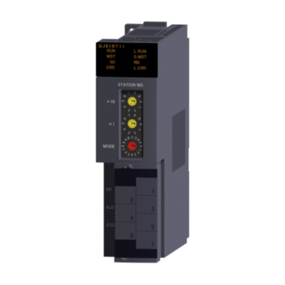
QJ61BT11 Control & Communication
Thank you for purchasing the Mitsubishi general-purpose PLC MELSEC-Q Series.
Before starting use, please read through this manual and the details manual to
ensure correct usage.
Before using this product, please read this manual and the relevant manuals introduced in
this manual carefully and pay full attention to safety to handle the product correctly.
The instructions given in this manual are concerned with this product. For the safety
instructions of the programmable controller system, please read the CPU module user's
manual.
In this manual, the safety instructions are ranked as "DANGER" and "CAUTION".
Note that the
circumstances.
Always follow the instructions of both levels because they are important to personal safety.
Please save this manual to make it accessible when required and always forward it to the
end user.
Downloaded from
ManualsNet.com
Link System Master/Local Module
! SAFETY PRECAUTIONS !
(Always read these instructions before using this equipment.)
Indicates that incorrect handling may cause hazardous conditions,
DANGER
resulting in death or severe injury.
Indicates that incorrect handling may cause hazardous conditions,
CAUTION
resulting in medium or slight personal injury or physical damage.
CAUTION
search engine
Type
Type code
IB(NA)-0800026-C(0009)MEE
© 1999 MITSUBISHI ELECTRIC CORPORATION
level may lead to a serious consequence according to the
Mitsubishi General-Purpose
Programmable Logic Controller
User's Manual
(Hardware)
QJ61BT11-U-H-JE
13JQ41
Advertisement

Related Manuals for Mitsubishi MELSEC-Q


Summary of Contents for Mitsubishi MELSEC-Q
- Page 1 Mitsubishi General-Purpose Programmable Logic Controller QJ61BT11 Control & Communication Link System Master/Local Module Thank you for purchasing the Mitsubishi general-purpose PLC MELSEC-Q Series. Before starting use, please read through this manual and the details manual to ensure correct usage. User's Manual...
- Page 2 [DESIGN PRECAUTIONS] CAUTION ! Do not bunch the control wires or communication cables with the main circuit or power wires, or install them close to each other. They should be installed 100mm (3.9inch) or more from each other. Not doing so could result in noise that may cause malfunction. [INSTALLATION PRECAUTIONS] CAUTION ! Use the PLC in an environment that meets the general specifications contained in the...
-
Page 3: Performance Specifications
(13JL91) Conformation to the EMC Directive and Low Voltage Instruction For details on making Mitsubishi PLC conform to the EMC directive and low voltage instruction when installing it in your product,please refer to Chapter 3,"EMC Directive and Low Voltage Instruction"of the PLC CPU User's Manual (Hardware).The CE logo is printed on the rating plate on the main body of the PLC that conforms to the EMC directive and low voltage instruction. -
Page 4: Mounting And Installation
Item Specifications Transmission rate Select from 156kbps/625kbps/2.5Mbps/5Mbps/10Mbps Maximum overall cable distance Differs according to transmission rate (Refer to section 2.2.) (Maximum transmission distance) Maximum connected 64 modules modules (for master station) No. of occupied stations (for local One station or four station) Remote input/output (RX, RY) : 2048 points Remote register (RWw) : 256 points (Master station →... - Page 5 3) Tighten the module installation screws within the following ranges. Screw position Tightening torque range 36 to 48N " cm Module installation screw (M3 screw) 42 to 58N " cm Terminal block terminal screw (M3 screw) 66 to 89N " cm Terminal block installation screw (M3.5 screw) POINT Always turn the power of the corresponding station OFF before mounting or removing the terminal...
-
Page 6: External Wiring
Name Details Station No. setting Set the module's station No. (Default setting: 0) switch <Setting range> STATION NO. Master station Local station : 1 to 64 Standby master station : 1 to 64 The "ERR." LED will turn ON if a value other than 0 to 64 is set. Transmission rate/ Set the module's transmission rate and operation state. -
Page 7: Outline Dimensions
1) The cable connecting sequence is not related with the station No. 2) Be sure to connect “terminal resistor” of the unit accessory to the units on both ends CC-Link system. Connect the terminal resistor between “DA” and “DB”. 3) In CC-Link system, the terminal resistor is different depending on the applied cable. "... - Page 8 Warranty Mitsubishi will not be held liable for damage caused by factors found not to be the cause of Mitsubishi; machine damage or lost profits caused by faults in the Mitsubishi products; damage, secondary damage, accident compensation caused by special factors unpredictable by Mitsubishi;...