Advertisement
Quick Links
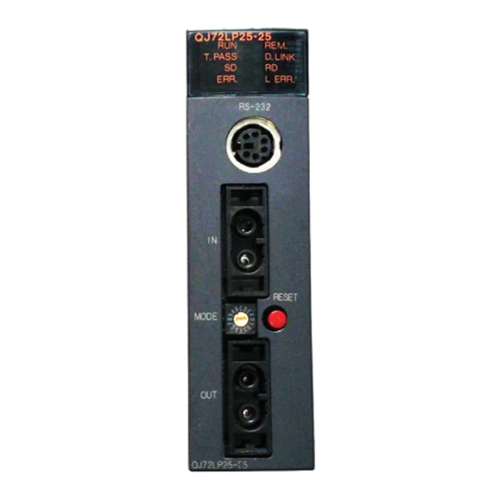
MELSECNET/H
Network Module
QJ72LP25-25, QJ72LP25G
Thank you for purchasing the Mitsubishi programmable controller
MELSEC-Q Series.
Prior to use, please read both this manual and detailed manual
thoroughly and familiarize yourself with the product.
©2000 MITSUBISHI ELECTRIC CORPORATION
User's Manual
QJ72BR15
MODEL
MODEL
CODE
IB(NA)-0800145-I(0809)MEE
(Hardware)
NET/H-R-U-H
13JT17
Advertisement

Related Manuals for Mitsubishi QJ72LP25-25


Summary of Contents for Mitsubishi QJ72LP25-25
- Page 1 MELSECNET/H Network Module User’s Manual (Hardware) QJ72LP25-25, QJ72LP25G QJ72BR15 Thank you for purchasing the Mitsubishi programmable controller MELSEC-Q Series. Prior to use, please read both this manual and detailed manual thoroughly and familiarize yourself with the product. MODEL NET/H-R-U-H MODEL...
- Page 2 SAFETY PRECAUTIONS (Always read these instructions before using this equipment.) Before using this product, please read this manual and the relevant manuals introduced in this manual carefully and pay full attention to safety to handle the product correctly. Precautionary notes in this manual cover only the installation of this product. For precautions on designing and discarding this product, refer to "Safety Precautions"...
- Page 3 [Installation Precautions] CAUTION Use the programmable controller in the operating environment that meets the general specifications given in the CPU module used. Using this programmable controller in an environment outside the range of the general specifications could result in electric shock, fire, erroneous operation, and damage to or deterioration of the product.
- Page 4 [Wiring Precautions] DANGER Completely turn off the externally supplied power used in the system when placing wiring. Not completely turning off all power could result in electric shock or damage to the product. CAUTION Solder coaxial cable connectors properly. Incomplete soldering may result in malfunction.
- Page 5 Voltage Directive, Chapter 2, 4, 5, 6 This manual confers no industrial property rights or any rights of any other kind, nor does it confer any patent licenses. Mitsubishi Electric Corporation cannot be held responsible for any problems involving industrial property rights which may occur as a result of using the contents noted in this manual.
-
Page 6: Table Of Contents
CONTENTS 1. Overview......................1 2. Performance Specifications ................2 3. Handling ......................6 3.1 Module Handling Precautions..............6 4. Part Identification Names................7 5. Wiring ......................10 6. External Dimensions ..................11... - Page 7 (1) For programmable controller system To configure a system meeting the requirements of the EMC and Low Voltage Directives when incorporating the Mitsubishi programmable controller (EMC and Low Voltage Directives compliant) into other machinery or equipment, refer to Chapter 9 "EMC AND LOW VOLTAGE DIRECTIVES"...
-
Page 8: Overview
1. Overview This manual explains how to handle the MELSECNET/H network module, model numbers QJ72LP25-25, QJ72LP25G and QJ72BR15 (hereinafter referred to as the network module). This network module is used as a remote I/O station of a remote I/O network in the MELSECNET/H network system, not in a PLC to PLC network. -
Page 9: Performance Specifications
2. Performance Specifications If the X/Y numbers are duplicate, only one side is taken into consideration.The following table shows the performance specifications for the network module: Specifications Item QJ72LP25-25 QJ72LP25G LX/LY 8192 points Remote master station remote sub-master, 16384 remote I/O station: 8192 points... - Page 10 Manual (Remote I/O network) for details. *4: Specialized skill and specific tools are required to connect the connector to the optical-fiber cable; the connector itself is a custom product. Please contact your nearest Mitsubishi Electric System Service Corporation when purchasing these items.
- Page 11 Specifications Item QJ72BR15 LX/LY 8192 points Remote master station remote sub-master 16384 station, remote I/O station: 8192 points points Remote sub-master station, remote I/O station Maximum number remote master station: 8192 points of links per network Remote master station remote sub-master 16384 station, remote I/O station: 8192 points points...
- Page 12 *1: The remote master station includes the multiplexed remote master station and multiplexed remote sub-master station. *2: On a multiplexed remote I/O network, one of 32 remote I/O stations works as a multiplexed remote sub-master station. *3: There are restrictions on the distance between stations, being determined according to the type of cable and number of stations.
-
Page 13: Handling
3. Handling CAUTION Use the programmable controller in the operating environment that meets the general specifications given in the user’s manual of the CPU module. Using this programmable controller in an environment outside the range of the general specifications could result in electric shock, fire, erroneous operation, and damage to or deterioration of the product. -
Page 14: Part Identification Names
*1: When resetting the system, press and hold the RESET switch for a second or more. If the pressing time is too short, the system may not be reset normally. If the system is not reset normally, try reset operation again. *2: Indicates the serial No. of the network module. (QJ72LP25-25 only) - Page 15 On: A communication error occurred Off: No communication error *1: The ERR. LED flashes on the QJ72LP25-25 and QJ72BR15 whose first five digits of the serial number is “02112” or later. *2: When a remote I/O module is used in a redundant power supply system, the REM. LED and ERR.
- Page 16 *1: When using the QJ72BR15, setting any of 33 to 64 will result in a setting error. However, the red ERR. LED will not turn ON. (b) Mode setting switch Set the operating mode. (Factory setting: 0) 1) QJ72LP25-25 *1 Setting range MODE 0: Online...
-
Page 17: Wiring
5. Wiring DANGER Completely turn off the externally supplied power used in the system when placing wiring. Not completely turning off all power could result in electric shock or damage to the product. CAUTION Solder coaxial cable connectors properly. Incomplete soldering may result in malfunction. -
Page 18: External Dimensions
6. External Dimensions (1) QJ72LP25-25, QJ72LP25G (0.91) 90 (3.54) 27.4 (1.08) *1: Please contact your nearest Mitsubishi Electric System Service Corporation for detail. Unit: mm (in.) - Page 19 (2) QJ72BR15 RS-232 STATION RESET MODE Q J 7 2 B R 1 5 90 (3.54) 27.4 (2.17) (1.08) Unit: mm (in.)
- Page 20 Warranty Mitsubishi will not be held liable for damage caused by factors found not to be the cause of Mitsubishi; machine damage or lost profits caused by faults in the Mitsubishi products; damage, secondary damage, accident compensation caused by special factors unpredictable by Mitsubishi;...