Table of Contents
Advertisement
Quick Links
Loop Control Module
Thank you for purchasing the Mitsubishi general-purpose
programmable controller MELSEC-Q series.
Prior to use, please read this manual thoroughly and familiarize
yourself with the product.
©2005 MITSUBISHI ELECTRIC CORPORATION
User's Manual
MODEL
Q62HLC-U-HW
MODEL
CODE
IB(NA)-0800319-C(0802)MEE
(Hardware)
Q62HLC
13JP75
Advertisement
Table of Contents

Related Manuals for Mitsubishi MELSEC-Q Q62HLC


Summary of Contents for Mitsubishi MELSEC-Q Q62HLC
- Page 1 Loop Control Module User’s Manual (Hardware) Q62HLC Thank you for purchasing the Mitsubishi general-purpose programmable controller MELSEC-Q series. Prior to use, please read this manual thoroughly and familiarize yourself with the product. MODEL Q62HLC-U-HW MODEL 13JP75 CODE IB(NA)-0800319-C(0802)MEE ©2005 MITSUBISHI ELECTRIC CORPORATION...
-
Page 2: Safety Precautions
SAFETY PRECAUTIONS (Read these precautions before using.) When using Mitsubishi equipment, thoroughly read this manual and the associated manuals introduced in this manual. Also pay careful attention to safety and handle the module properly. These SAFETY PRECAUTIONS classify the safety precautions into two categories: "DANGER"... - Page 3 [INSTALLATION PRECAUTIONS] CAUTION Use the programmable controller in an environment that meets the general specifications contained in the CPU user's manual. Using this programmable controller in an environment outside the range of the general specifications may cause electric shock, fire, malfunction, and damage to or deterioration of the product.
-
Page 4: Revisions
Chapter 6 This manual confers no industrial property rights or any rights of any other kind, nor dose it confer any patent licenses. Mitsubishi Electric Corporation cannot be held responsible for any problems involving industrial property rights which may occur as a result of using the contents noted in this manual. -
Page 5: Table Of Contents
CONTENTS SAFETY PRECAUTIONS ................A-1 REVISIONS ....................A-3 About the Manuals ..................A-4 Conformation to the EMC Directive and Low Voltage Instruction ....A-5 1. OVERVIEW....................1 2. SPECIFICATIONS ..................1 2.1 Performance Specifications ..............1 2.2 Types, Measured Ranges and Data Resolutions of Usable Input Sensors.3 2.3 Indicated Accuracy for Ambient Temperature ...........3 2.4 Operation at Input Disconnection..............4 3. -
Page 6: Conformation To The Emc Directive And Low Voltage Instruction
Conformation to the EMC Directive and Low Voltage Instruction (1) About sequence system When incorporating the Mitsubishi programmable controller into other machinery or equipment and keeping compliance with the EMC and low voltage directives, refer to Chapter 9, "EMC Directive and Low Voltage Instruction"... -
Page 7: Overview
1. OVERVIEW This user's manual provides the specifications, handling, part names and others of the following loop control modules (hereafter abbreviated to the Q62HLC) used with the MELSEC-Q series CPU modules. Q62HLC loop control module • 2. SPECIFICATIONS The specifications of the Q62HLC are indicated below. 2.1 Performance Specifications Item Specifications... - Page 8 Item Specifications Specification for analog output *2 Output points 2 points (2 channels) Digital input 16-bit signed binary Analog output Current Digital input value: 0 to 1000 (When using simplified analog output Output characteristic 0 to 4000), Output range:4 to 20mA Maximum resolution Ambient temperature: Full scale...
-
Page 9: Types, Measured Ranges And Data Resolutions Of Usable Input Sensors.3
2.2 Types, Measured Ranges and Data Resolutions of Usable Input Sensors Input Input range Digital value Data resolution -200 to 1372°C -2000 to 13720 -200 to 1200°C -2000 to 12000 -200 to 400°C -2000 to 4000 -50 to 1768°C -500 to 17680 -50 to 1768°C -500 to 17680 Thermocouple... -
Page 10: Operation At Input Disconnection
(2) Ambient temperature 0 to 55°C Item Error Less than -100°C 2.0°C K,J,T,E,PL II –100 to less than 500°C 1.0°C 500°C or more (indicated×(0.2%)+1digit) S,R,N, –50 to less than 1000°C 2.0°C Thermocouple W5Re/W26Re 1000°C or more (indicated×(0.2%)+1digit) Less than 400°C 140.0°C 400 to less than 1000°C 2.0°C... -
Page 11: Loading And Installation
3. LOADING AND INSTALLATION 3.1 Handling Instructions There are the following instructions for handling the Q62HLC. (1) Do not drop the case and connectors of the module and subject them to hard impact. (2) Tighten the module fixing screws and terminal screws of the module within the following ranges. -
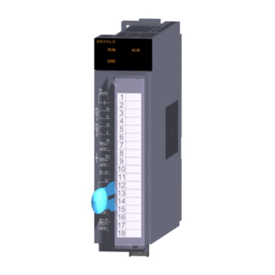
Page 12: Names And Settings Of The Parts
4. NAMES AND SETTINGS OF THE PARTS Q62HLC Q62HLC ERR. ERR. 24VDC 24VDC TC+/ TC+/ TC-/ TC-/ V-/I- V-/I- TC+/ V-/I- V-/I- TC-/ TC-/ [Condition without temperature compensation resistor] Number Name and Appearance Description Indicates the operating status of the Q62HLC. : Operating normally. - Page 13 (1) Terminal number and signal number Terminal Signal Number Content Number 24VDC + 24VDC + external power supply for current output 24VDC - 24VDC - external power supply for current output Current output + OUT1 Current output - Current output + OUT2 Current output - Current input +...
-
Page 14: Wiring
5. WIRING 5.1 Wiring Instructions (1) Use separate cables for the AC control circuit and Q62HLC's external input output signals to avoid the influence of AC side surges and inductions. (2) Do not run the module cables near, or bundle them with, the main circuit and high-voltage cables and the load cables from other than the programmable controller. - Page 15 (c) For the voltage input Q62HLC Signal source -10 to 10VDC V-/I- (d) For the current input Q62HLC Signal source 0 to 20mADC V-/I- (2) Output Q62HLC Control equipment 0 to 600 (3) External power supply Q62HLC 24VDC+ DC/DC 24VDC converter 24DCV- *1: Always use shielded wires for cables.
-
Page 16: Setting From Gx Developer
6. SETTING FROM GX Developer The Q62HLC allows you to set the output status at an error stop of the programmable controller CPU by making the intelligent function module switch setting. Make the intelligent function module switch setting using the I/O assignment setting of GX Developer. -
Page 17: External Dimensions
7. EXTERNAL DIMENSIONS Q62HLC ERR. 24VDC TC+/ TC-/ V-/I- V-/I- TC-/ M3 screw M3 screw (accessory) (accessory) 49(1.93) 57.5(2.26) 90(3.54) 112(4.41) 27.4(1.08) FG terminal L shaped fixture (accessory) Unit: mm (inch) - Page 18 Warranty Mitsubishi will not be held liable for damage caused by factors found not to be the cause of Mitsubishi; machine damage or lost profits caused by faults in the Mitsubishi products; damage, secondary damage, accident compensation caused by special factors unpredictable by Mitsubishi;...