Table of Contents
Advertisement
nordictrack.com
USER'S MANUAL
Model No. NTEX29017.0
Serial No.
Write the serial number in the space
above for reference.
Serial Number
Decal
(under frame)
ACTIVATE YOUR
WARRANTY
To register your product and
activate your warranty today,
go to my.nordictrack.com.
CUSTOMER CARE
For service at any time, go to
nordictrackservice.com.
Or call 1-800-TO-BE-FIT
(1-800-862-3348)
Mon.–Fri. 6 a.m.–6 p.m. MT
Sat. 8 a.m.–12 p.m. MT
Please do not contact the store.
CAUTION
Read all precautions and
instructions in this manual before
using this equipment. Keep this
manual for future reference.
Advertisement
Table of Contents

Related Manuals for NordicTrack NTEX29017.0


Summary of Contents for NordicTrack NTEX29017.0
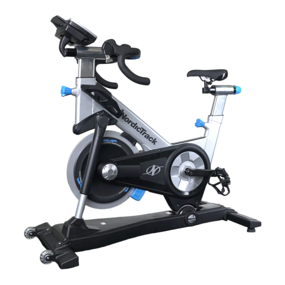
- Page 1 USER’S MANUAL Model No. NTEX29017.0 Serial No. Write the serial number in the space above for reference. Serial Number Decal (under frame) ACTIVATE YOUR WARRANTY To register your product and activate your warranty today, go to my.nordictrack.com. CUSTOMER CARE For service at any time, go to nordictrackservice.com.
-
Page 2: Table Of Contents
NORDICTRACK and IFIT are registered trademarks of ICON Health & Fitness, Inc. Google Maps is a trademark of Google Inc. ANT+™ is a trademark of Garmin Ltd. or its subsidiaries. Polar is a registered trademark of Polar... -
Page 3: Important Precautions
IMPORTANT PRECAUTIONS WARNING: To reduce the risk of burns, fire, electric shock, or injury to persons, read all important precautions and instructions in this manual and all warnings on your training bike before using your training bike. ICON assumes no responsibility for personal injury or property damage sustained by or through the use of this product. - Page 4 15. The training bike should not be used by 17. Always keep your back straight while using persons weighing more than 350 lbs. the training bike; do not arch your back. (159 kg). 18. Over exercising may result in serious injury 16.
- Page 6 STANDARD SERVICE PLANS...
-
Page 7: Before You Begin
BEFORE YOU BEGIN Congratulations for selecting the revolutionary reading this manual, please see the back cover of this NORDICTRACK training bike. The training bike is manual. To help us assist you, note the product model ® unlike any ordinary exercise bike. With full adjust- number and serial number before contacting us. -
Page 8: Part Identification Chart
PART IDENTIFICATION CHART Use the drawings below to identify the small parts needed for assembly. The number in parentheses below each drawing is the key number of the part, from the PART LIST near the end of this manual. The number following the key number is the quantity needed for assembly. -
Page 9: Assembly
To avoid damaging parts, do not use • To avoid damaging parts, do not use power tools. power tools. 1. Go to my.nordictrack.com on your computer and register your product. • activates your warranty • saves you time if you ever need to contact Customer Care •... - Page 10 3. Attach the Front Stabilizer (3) to the Base (2) with two M10 x 60mm Bolts (115), two M10 Washers (112), and two M10 Locknuts (116). 4. While a second person holds the Console Mount (66) near the Handlebar Post (7), route the frame Avoid pinching the wires and cable (A) upward through the Console wires and cable (A)
- Page 11 5. Remove the four M4 x 10mm Screws (12), and then remove the Console Cover (11) from the Console (10); set these parts aside. Avoid pinching the wires and While a second person holds the Console (10) cable (A, B) near the Console Mount (66), connect the con- sole wires and cable (B) to the matching frame wires and cable (A).
-
Page 12: How To Use The Training Bike
HOW TO USE THE TRAINING BIKE HOW TO PLUG IN THE POWER CORD A temporary adapter may 2-pole Receptacle This product must be grounded. If it should mal- be used to function or break down, grounding provides a path of connect the Adapter least resistance for electric current to reduce the risk... - Page 13 FEATURES OF THE TRAINING BIKE HOW TO ADJUST THE GEOMETRY OF THE TRAINING BIKE Measuring Watts The training bike can be adjusted to match the geom- Each training bike is individually calibrated to measure etry of your road bike to promote correct form and to your power output and to allow you to monitor your ensure proper training of the muscles.
- Page 14 How to Adjust the Saddle Post How to Adjust the Handlebar Carriage For effective training, the saddle should be at the To adjust the proper height. As you pedal, there should be a slight position of the bend in your knees when the pedals are in the lowest handlebar, loosen position.
- Page 15 Download training workouts designed to Choose and download sets of weight-loss help you reach your personal goals. workouts. Measure your progress by competing against other users in the iFit community. Go to iFit.com to learn more. Maverick EBNT29017 NTEX29017.0...
- Page 16 FEATURES OF THE CONSOLE HOW TO TURN ON THE POWER The advanced console offers an array of features IMPORTANT: If the training bike has been exposed to cold temperatures, allow it to warm to room tem- designed to make your workouts more effective and perature before you turn on the power.
- Page 17 HOW TO USE THE TOUCH SCREEN 2. Check for firmware updates. The console features a tablet with a full-color touch First, see step 1 on page 24 and step 2 on page screen. The following information will help you become 26 and select the maintenance mode.
- Page 18 HOW TO USE THE MANUAL MODE Change gears by pressing the buttons on the shifters. Note: After you press a button, it will take 1. Touch the screen or begin pedaling to activate a moment for the training bike to change to the the console.
- Page 19 6. Do intervals if desired. 7. Wear a heart rate monitor and measure your heart rate if desired. During a workout, you can use the interval screen to measure your performance for short periods of You can wear an optional heart rate monitor to time.
- Page 20 HOW TO USE AN ONBOARD WORKOUT At the end of the first segment of the workout, the incline will automatically adjust to the incline level 1. Touch the screen or begin pedaling to activate for the next segment. the console. When the incline changes, the resistance of the See HOW TO TURN ON THE POWER on pedals will also change.
- Page 21 HOW TO USE A SET-A-GOAL WORKOUT Note: You can manually override the incline set- tings by pressing the Grade buttons. To return to 1. Touch the screen or begin pedaling to activate the programmed incline settings of the work- the console. out, touch the Follow Workout button.
- Page 22 HOW TO USE AN IFIT WORKOUT To switch users within your iFit account, touch the user button at the bottom of the screen. If more To use an iFit workout, the console must be connected than one user is associated with your iFit account, to a wireless network (see HOW TO USE THE a list of users will appear.
- Page 23 7. Follow your progress. HOW TO USE THE SOUND SYSTEM See step 5 on page 18. The screen may also To listen to the console audio with your personal show a map of the route and a marker indicating headphones or ear buds, plug your headphones into your progress.
- Page 24 HOW TO USE THE EQUIPMENT SETTINGS MODE Enable checkbox or the Disable checkbox. Then, touch the back button on the screen. IMPORTANT: Some of the features described may not be enabled. Occasionally, a firmware update may Note: To select a time for automatic console cause your console to function slightly differently.
- Page 25 8. Turn on or turn off the display demo mode. touch the Enable checkbox or the Disable check- box. Then, touch the back button on the screen. The console features a display demo mode, 12. Select a time zone. designed to be used if the training bike is displayed in a store.
- Page 26 HOW TO USE THE MAINTENANCE MODE updates are always designed to improve your train- ing experience. IMPORTANT: Some of the features described may not be enabled. Occasionally, a firmware update may 4. Calibrate the incline system of the training bike. cause your console to function slightly differently.
- Page 27 HOW TO USE THE WIRELESS NETWORK MODE When a list of networks appears, touch the desired network. Note: You will need to know your network The console features a wireless network mode that name (SSID). If your network has a password, you allows you to set up a wireless network connection.
-
Page 28: Fcc Information
FCC INFORMATION This equipment has been tested and found to comply with the limits for a Class B digital device, pursuant to Part 15 of the FCC Rules. These limits are designed to provide reasonable protection against harmful interference in a residential installation. This equipment generates, uses, and can radiate radio frequency energy and, if not installed and used in accordance with the instructions, may cause harmful interference to radio communications. -
Page 29: Exercise Guidelines
EXERCISE GUIDELINES Aerobic Exercise—If your goal is to strengthen your WARNING: cardiovascular system, you must perform aerobic Before beginning this exercise, which is activity that requires large amounts or any exercise program, consult your physi- of oxygen for prolonged periods of time. For aerobic cian. - Page 30 SUGGESTED STRETCHES The correct form for several basic stretches is shown at the right. Move slowly as you stretch; never bounce. 1. Toe Touch Stretch Stand with your knees bent slightly and slowly bend forward from your hips. Allow your back and shoulders to relax as you reach down toward your toes as far as possible.
- Page 31 NOTES...
-
Page 32: Part List
PART LIST Model No. NTEX29017.0 R0317A Key No. Qty. Description Key No. Qty. Description Frame Cap B Base Lower Wedge Front Stabilizer Upper Wedge Rear Stabilizer Saddle Stabilizer Guard Releasable Cable Tie Pivot Clamp Pedal Set Handlebar Post M4 x 8mm Washer... - Page 33 Key No. Qty. Description Key No. Qty. Description Shifter Brace M6 x 40mm Bolt Right Shifter Assembly M4 x 12mm Pan Head Screw Left Shifter Cap M2 x 15mm Screw Left Shifter Cover M4 x 40mm Screw M3 x 25mm Screw M5 Star Washer Right Shifter Cap M4 x 8mm Hex Screw...
-
Page 34: Exploded Drawing
EXPLODED DRAWING A Model No. NTEX29017.0 R0317A 79 77... - Page 35 EXPLODED DRAWING B Model No. NTEX29017.0 R0317A...
-
Page 36: Ordering Replacement Parts
ORDERING REPLACEMENT PARTS To order replacement parts, please see the front cover of this manual. To help us assist you, be prepared to provide the following information when contacting us: • the model number and serial number of the product (see the front cover of this manual) •...