Advertisement
Table of Contents
- 1 Table of Contents
- 2 Warning Decal Placement
- 3 Important Precautions
- 4 Before You Begin
- 5 Part Identification Chart
- 6 Assembly
- 7 The Chest Heart Rate Monitor
- 8 How to Use the Elliptical
- 9 Fcc Information
- 10 Maintenance and Troubleshooting
- 11 Exercise Guidelines
- 12 Part List
- 13 Exploded Drawing
- 14 Ordering Replacement Parts
- 15 Limited Warranty
- Download this manual
www.nordictrack.com
Model No. NTEL71615.1
Serial No.
Write the serial number in the space
above for reference.
Serial
Number
Decal
ACTIVATE YOUR
WARRANTY
To register your product and
activate your warranty today, go
to www.nordictrackservice.com/
registration.
CUSTOMER CARE
For service at any time, go to
www.nordictrackservice.com.
Or call 1-800-TO-BE-FIT
(1-800-862-3348)
Mon.–Fri. 6 a.m.–6 p.m. MT
Sat. 8 a.m.–12 p.m. MT
Please do not contact the store.
CAUTION
Read all precautions and
instructions in this manual before
using this equipment. Keep this
manual for future reference.
USER'S MANUAL
Advertisement
Table of Contents

Related Manuals for NordicTrack A.C.T. NTEL71615


Summary of Contents for NordicTrack A.C.T. NTEL71615
- Page 1 USER’S MANUAL Model No. NTEL71615.1 Serial No. Write the serial number in the space above for reference. Serial Number Decal ACTIVATE YOUR WARRANTY To register your product and activate your warranty today, go to www.nordictrackservice.com/ registration. CUSTOMER CARE For service at any time, go to www.nordictrackservice.com.
-
Page 2: Table Of Contents
Note: The decal(s) may not be shown at actual size. NORDICTRACK is a registered trademark of ICON Health & Fitness, Inc. IFIT is a registered trademark of ICON Health & Fitness, Inc. The BLUETOOTH word mark and logos are registered trademarks of Bluetooth SIG, Inc. -
Page 3: Important Precautions
IMPORTANT PRECAUTIONS WARNING: To reduce the risk of serious injury, read all important precautions and instructions in this manual and all warnings on your elliptical before using your elliptical. ICON assumes no responsibility for personal injury or property damage sustained by or through the use of this product. - Page 5 STANDARD SERVICE PLANS...
-
Page 6: Before You Begin
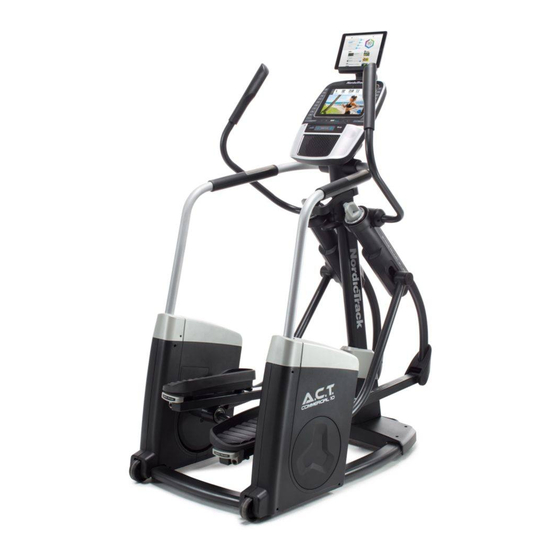
BEFORE YOU BEGIN Thank you for selecting the revolutionary reading this manual, please see the front cover of this NORDICTRACK ACT COMMERCIAL 10 elliptical. manual. To help us assist you, note the product model ® The ACT COMMERCIAL 10 elliptical provides an number and serial number before contacting us. -
Page 7: Part Identification Chart
PART IDENTIFICATION CHART Use the drawings below to identify the small parts needed for assembly. The number in parentheses below each drawing is the key number of the part, from the PART LIST near the end of this manual. The number following the key number is the quantity needed for assembly. -
Page 8: Assembly
ASSEMBLY • Assembly requires two persons. • In addition to the included tool(s), assembly requires the following tools: • Place all parts in a cleared area and remove the one Phillips screwdriver packing materials. Do not dispose of the packing materials until you fi... - Page 9 3. Have a second person lift the Right Pedal (9) and the Right Pedal Arm (15). Using a plastic bag to keep your fingers clean, apply some of the included grease to the right Link Arm Bracket (43) in the location shown. Tip: Avoid pinching your fingers.
- Page 10 5. Attach the lower end of the Right Handrail (5) to the Frame (1) with four M8 x 20mm Screws (61); do not tighten the Screws yet. Attach the lower end of the Left Handrail (4) in the same way. See step 2.
- Page 11 7. Align the plastic post inside the Right Handrail Cover (7) with the indicated hole in the Right Shield Cover (76). Press the Right Handrail Cover (7) onto the Right Shield Cover (76) and onto the Right Outer Post and Inner Shields (17, 19). Attach the Right Handrail Cover (7) with an Hole M4 x 16mm Screw (67).
- Page 12 9. Hold the Rear Upright Cover (21) against the Upright (2) and against the Console (3). Attach the Rear Upright Cover to the Upright with five M4 x 16mm Screws (67); start all the Screws, and then tighten them. 10. Press the tabs on the Front Upright Cover (20) into the Rear Upright Cover (21).
- Page 13 11. Identify the Right Handlebar (11). Attach the Right Handlebar (11) to the Right Handlebar Arm (13) with three M8 x 25mm Flat Head Screws (68). Attach the Left Handlebar (10) in the same way. 12. Attach the right Handlebar Cover (31) to the Right Handlebar (11) with three M4 x 16mm Screws (67).
- Page 14 13. Attach the Tablet Holder (145) to the Console (3) with four #8 x 12mm Screws (146); start all the Screws, and then tighten them. 14. Plug the Power Adapter (84) into the receptacle on the frame of the elliptical. Note: To plug the Power Adapter (84) into an outlet, see HOW TO PLUG IN THE POWER ADAPTER on page 16.
-
Page 15: The Chest Heart Rate Monitor
THE CHEST HEART RATE MONITOR HOW TO PUT ON THE HEART RATE MONITOR • Store the heart rate monitor in a warm, dry place. Do not store the heart rate monitor in a plastic bag or If the heart rate monitor looks like the one shown other container that may trap moisture. -
Page 16: How To Use The Elliptical
HOW TO USE THE ELLIPTICAL HOW TO PLUG IN THE POWER ADAPTER HOW TO LEVEL THE ELLIPTICAL IMPORTANT: If the elliptical has been exposed to If the elliptical rocks cold temperatures, allow it to warm to room tem- slightly on your perature before you plug in the power adapter. - Page 17 HOW TO ADJUST THE POSITIONS OF THE HOW TO EXERCISE ON THE ELLIPTICAL PEDALS To mount the elliptical, hold the handlebars and step Each pedal can be adjusted to several positions. To onto the pedal that is in the lower position. Then, step adjust each pedal, simply pull the pedal handle out- onto the other pedal.
- Page 18 CONSOLE DIAGRAM MAKE YOUR FITNESS GOALS A REALITY WITH Upload your workout results to the iFit cloud IFIT.COM and track your accomplishments. With your new iFit-compatible fitness equipment, you can use an array of features on iFit.com to make your Set calorie, time, or distance goals for your fitness goals a reality: workouts.
- Page 19 FEATURES OF THE CONSOLE HOW TO ACTIVATE THE CONSOLE The advanced console offers an array of features The included power adapter must be used to operate designed to make your workouts more effective and the elliptical. See HOW TO PLUG IN THE POWER enjoyable.
- Page 20 HOW TO USE THE TOUCH SCREEN HOW TO SET UP THE CONSOLE The console features a tablet with a full-color touch Before using the elliptical for the first time, set up the screen. The following information will help you become console.
- Page 21 The console is now ready for you to begin working out. Note: After you press a button, it will take a The following pages explain the various workouts and moment for the pedals to reach the selected other features that the console offers. resistance level.
- Page 22 When your pulse is detected, your heart rate HOW TO USE AN ONBOARD WORKOUT will be shown. For the most accurate heart rate reading, hold the contacts for at least 15 1. Touch the screen, press any button on the seconds.
- Page 23 As you exercise, keep your pedaling speed near To pause the workout, touch either the back button the target cadence for the current segment. The or the home button at the bottom of the screen. To target zone meter will prompt you to increase, continue the workout, touch the Resume button.
- Page 24 HOW TO USE A SET-A-GOAL WORKOUT If the resistance level for the current segment is too high or too low, you can manually override the 1. Touch the screen, press any button on the setting by pressing the Resistance buttons. If you console, or begin pedaling to turn on the press a Resistance button, you can then manu- console.
- Page 25 HOW TO USE AN IFIT WORKOUT For more information about the iFit workouts, please see www.iFit.com. Note: To use an iFit workout, you must have access to a wireless network (see HOW TO USE THE When you select an iFit workout, the screen will WIRELESS NETWORK MODE on page 29).
- Page 26 HOW TO USE THE EQUIPMENT SETTINGS MODE checkbox or the Disable checkbox. Then, touch the back button on the screen. IMPORTANT: Some of the features described may not be enabled. Occasionally, a firmware update 6. Select a time for the cadence timeout. may add new features or cause your console to function slightly differently.
- Page 27 9. Select a language. 14. Select an update time. To select a language, touch the Language button To select a time for automatic console updates, and select the desired language. touch the Update Time button and select the desired time. Then, touch the back button on the 10.
- Page 28 HOW TO USE THE MAINTENANCE MODE 4. Calibrate the screen. IMPORTANT: Some of the features described may If the screen is not properly calibrated, it will be not be enabled. Occasionally, a firmware update difficult for you to touch the correct buttons on the may add new features or cause your console to screen.
- Page 29 HOW TO USE THE WIRELESS NETWORK MODE name (SSID). If your network has a password, you will also need to know the password. The console features a wireless network mode that allows you to set up a wireless network connection. An information box will ask if you want to connect to the wireless network.
- Page 30 HOW TO USE THE SOUND SYSTEM HOW TO USE THE INTERNET BROWSER To play music or audio books through the console Note: To use the internet browser, you must have sound system while you exercise, plug a 3.5 mm male access to a wireless network including a wireless to 3.5 mm male audio cable (not included) into the jack router (802.11b/g/n) with SSID broadcast enabled (hid-...
-
Page 31: Fcc Information
FCC INFORMATION This equipment has been tested and found to comply with the limits for a Class B digital device, pursuant to Part 15 of the FCC Rules. These limits are designed to provide reasonable protection against harmful interference in a residential installation. This equipment generates, uses, and can radiate radio frequency energy and, if not installed and used in accordance with the instructions, may cause harmful interference to radio communications. -
Page 32: Maintenance And Troubleshooting
MAINTENANCE AND TROUBLESHOOTING MAINTENANCE Using a standard screwdriver, carefully pry off the Left Shield Disc (103). Regular maintenance is important for optimal performance and to reduce wear. Inspect and properly tighten all parts each time the elliptical is used. Replace any worn parts immediately. To clean the elliptical, use a damp cloth and a small amount of mild soap. - Page 33 HOW TO ADJUST THE DRIVE BELT Next, loosen the Pivot Screw (97), tighten the Belt Adjustment Screw (79) until the Drive Belt (57) is tight, If the pedals slip while you are pedaling, even while and then retighten the Pivot Screw. the resistance is adjusted to the highest level, the drive belt may need to be adjusted.
-
Page 34: Exercise Guidelines
EXERCISE GUIDELINES Burning Fat—To burn fat effectively, you must exer- WARNING: cise at a low intensity level for a sustained period of Before beginning this time. During the first few minutes of exercise, your or any exercise program, consult your physi- body uses carbohydrate calories for energy. -
Page 35: Part List
PART LIST Model No. NTEL71615.1 R0116A Key No. Qty. Description Key No. Qty. Description Frame Wheel Upright Leveling Foot Console Pulley Left Handrail Right Frame Cover Right Handrail Eddy Mechanism Left Handrail Cover Left Frame Cover Right Handrail Cover Drive Belt Link Arm M8 Jam Nut Right Pedal... - Page 36 Key No. Qty. Description Key No. Qty. Description M10 Split Washer Pedal Arm Axle Left Shield Cover M6 x 36mm Bolt Left Shield Disc Adjustment Assembly Left Shield Insert M8 x 45mm Bolt M10 Locknut Guide Rod M4 x 19mm Screw M6 x 45mm Screw Right Pedal Handle M10 x 20mm Screw...
-
Page 37: Exploded Drawing
EXPLODED DRAWING A Model No. NTEL71615.1 R0116A... - Page 38 EXPLODED DRAWING B Model No. NTEL71615.1 R0116A...
- Page 39 EXPLODED DRAWING C Model No. NTEL71615.1 R0116A...
-
Page 40: Ordering Replacement Parts
ORDERING REPLACEMENT PARTS To order replacement parts, please see the front cover of this manual. To help us assist you, be prepared to provide the following information when contacting us: • the model number and serial number of the product (see the front cover of this manual) •...