Datalogic Magellan 3300HSi Product Reference Manual
Hide thumbs
Also See for Magellan 3300HSi:
- Product manual (216 pages) ,
- Product reference manual (208 pages) ,
- Quick reference manual (28 pages)

Related Manuals for Datalogic Magellan 3300HSi


Summary of Contents for Datalogic Magellan 3300HSi
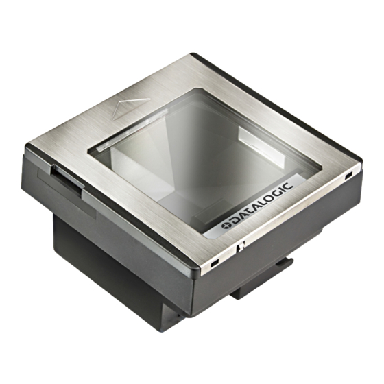
- Page 1 Magellan 3300HSi In-Counter Horizontal Single Plane Scanner Product Reference Guide...
- Page 2 Datalogic and the Datalogic logo are registered trademarks of Datalogic S.p.A. in many countries, including the U.S.A. and the E.U. All other brand and product names may be trademarks of Datalogic S.p.A. or of Dat- alogic Group companies, registered in many countries, including the U.S. and the E.U.
-
Page 3: Table Of Contents
Table of Contents Chapter 1. GETTING STARTED..................................1 About This Manual ................................... 1 Manual Conventions ................................1 Connecting the Scanner ................................... 2 Error Codes ......................................4 Installation ......................................4 LED and Beeper Indicators ................................6 Programming ....................................7 Using the Programming Bar Codes ............................7 Resetting the Standard Product Defaults ............................. - Page 4 Single Cable RS-232 Use ETX ..............................66 Set Single Cable RS-232 ETX Character ..........................66 Single Cable Pacesetter Plus ..............................67 Single Cable Datalogic Extensions ............................67 USB-OEM Interface Features ..............................68 USB-OEM Device usage ..............................68 IBM ......................................68 IBM Transmit Labels in Code 39 Format ........................
- Page 5 Disable/Enable UPC-A ................................89 Check Digit Transmission ..............................90 Number System Transmission ............................. 90 Expand UPC-A to EAN-13 ..............................91 UPC-E ....................................... 92 Disable/Enable UPC-E ................................92 Check Digit Transmission ..............................92 Number System Digit ................................93 Expand to UPC-E to UPC-A ..............................93 Expand UPC-E to EAN13 ................................
- Page 6 Interleaved 2 of 5 ..................................118 Disable/Enable Interleaved 2 of 5 ............................118 Check Digit Calculation ................................. 119 Check Digit Transmit ................................119 Length Control ..................................120 Interleaved 2 of 5 Length 1, Length 2 Programming Instructions .................. 121 Codabar ......................................121 Disable/Enable Codabar ..............................
- Page 7 Application code load to scanner ..........................194 Configuration load to scanner ............................. 194 Appendix I. Handheld Data Format Requirements General ......................195 Datalogic Handheld Data Format Requirements ......................196 RSS-14 ................................... 196 RSS Expanded ................................196 UPC-A ..................................... 196 UPC-A with 2-Digit Supplemental ..........................196 UPC-A with 5-Digit Supplemental ..........................
- Page 8 EAN-8 with 5-Digit Supplemental ..........................198 EAN-8 with Code 128 Supplemental .......................... 198 EAN-13 ................................... 198 EAN-13 with 2-Digit Supplemental ..........................198 EAN-13 with 5-Digit Supplemental ..........................198 EAN-13 with Code 128 Supplemental ........................198 Code 39 ..................................199 Code 39-Pharmacode ..............................199 I 2 of 5 .....................................
-
Page 9: Chapter 1 Getting Started
Chapter 1 Getting Started The Magellan 3300HSi Horizontal Single Plane Scanner is designed for small counter retail checkout environments where there is a relatively high number of transactions with a fairly small number of items per transaction. The scanner has a reduced footprint, allowing more room for item merchandising of high margin impulse items clustered around the P.O.S. -
Page 10: Connecting The Scanner
Connecting the Scanner The scanner kit you ordered to match your interface should provide a compati- ble cable for your installation. Alternatively, if your scanner receives Power Off the Terminal (POT) it might be possible to connect using a cable from a previ- ously existing installation (except for USB). - Page 11 Connect the scanner to a USB port on the terminal/PC using USB Connection — the correct USB cable for the interface type you ordered. Reference Figure USB installations may require a power connection via an approved A/C Adapter as shown in Figure 1 b or Figure 1 c. For example, this would be the case if the scanner is con- NOTE nected along with a number of other devices to a non-pow-...
-
Page 12: Error Codes
Error Codes If an error is detected, the scanner will sound a long low tone (for three sec- onds) and flash its LED, indicating a failure. When this occurs, remove the top cover and press the Scanner Push Button to hear the error code. If it is config- ured to do so, the scanner will sound a series of beeps corresponding to the error code and/or flash its LED simultaneous to the beeps. - Page 13 • Figure 3c provides dimensions if an adapter fixture holding the scanner will be recessed to be flush with the countertop. 3. Remove the Connector Cover, then connect and route the cables at the scanner. 4. Seat the scanner or in the countertop opening (or adapter). 5.
-
Page 14: Led And Beeper Indicators
LED and Beeper Indicators The scanner’s beeper sounds and its green LED illuminates to indicate various functions or errors on the scanner. The tables below list these indications. One exception to the behaviors listed in the tables is that the scanner’s functions are programmable, and may or may not be turned on. -
Page 15: Programming
Table 1. Beeper Functions BEEPER INDICATION COMMENT INDICATION The Power-On Beep indication is a configurable fea- Power On ture which can be enabled or disabled. When enabled, Single beep Beep this beep Indicates the scanner has finished all its power up tests and is now ready for operation. The good read beep indication is configurable. -
Page 16: Resetting The Standard Product Defaults
Resetting the Standard Product Defaults If you are unsure of what programming options are in your scanner, or you’ve Stan- changed some options and want the factory settings restored, scan the dard Product Default Settings bar code below. This will copy the factory config- uration for the currently active interface to the current configuration. -
Page 17: Bar Code Mask
Bar Code Mask Cut a hole in this page and remove it from the manual as indicated to create a sleeve through which bar codes (starting in the following section) can be indi- vidually viewed and scanned. It is important that only one bar code at a time be presented to the scanner. -
Page 18: Going Green
Going Green Thank you for using the bar code mask on the opposite side of this page. This manual has been formatted to minimize the quantity of pages needed to pro- vide all of the programming bar codes available for this product. LED Class CLASS 1 LED PRODUCT APPARECCHIO LED CLASSE 1 LED KLASSE 1 APPAREIL A LED DE CLASSE 1... -
Page 19: Chapter 2 Programming
Chapter 2 Programming Introduction to Label Programming The programming bar code labels contained in this manual will allow you to customize and configure features and settings for your scanner (scanner/ scale). To ensure full compatibility and proper function, use only the program- ming bar codes in this manual and other product-specific publications to pro- gram scanner features. -
Page 20: Resetting The Standard Product Defaults
Resetting the Standard Product Defaults If you are unsure of what programming options are in your scanner, or you’ve Stan- changed some options and want the factory settings restored, scan the dard Product Default Settings bar code below. This will copy the factory config- uration for the currently active interface to the current configuration. -
Page 21: Using A Bar Code Mask
Using a Bar Code Mask The programming bar codes in this manual have been placed as multiples per page. In order to present them only one at a time to the scanner, a bar code mask is provided on the opposite side of this page. Going Green Thank you for using the bar code mask on the opposite side of this page. -
Page 22: Bar Code Mask
Bar Code Mask Cut a hole in this page and remove it from the manual as indicated to create a sleeve through which bar codes (starting in the following section) can be indi- vidually viewed and scanned. It is important that only one bar code at a time be presented to the scanner. -
Page 23: Double Read Timeout For Linear Labels
General Features Double Read Timeout for Linear Labels This Double Read Timeout feature sets a time limit that determines how much time must pass before reading the same linear label again (e.g. two identical items in succession). START / END PROGRAMMING bar codes 0.1 Second 0.2 Second... - Page 24 Double Read Timeout for Linear Labels (continued) START / END PROGRAMMING bar codes 0.7 Second 0.8 Second 0.9 Second 1 Second Magellan™ 3300HSI...
-
Page 25: Double Read Timeout For 2D Labels
Double Read Timeout for 2D Labels This Double Read Timeout feature specifies the minimum allowable time between consecutive good reads of the same PDF 417, Micro PDF 417 Data Matrix, QR Code, Maxicode, Aztec or Composite label. START / END PROGRAMMING bar codes 0.7 Second DEFAULT... -
Page 26: Scanner Button Options
Scanner Button Options This feature allows the user to configure the scanner / volume button (which is accessible under the removable top cover) to different modes of operation. Options are: • All functions (volume, tone, diagnostics, and reset) • Enable only volume, tone, and reset •... -
Page 27: Camera Button Mode
Controls the function associated with the "Picture Taking" button This is an optional feature. In order to use it, an accessory “Remote Camera Button” (avail- able from Datalogic) will need to be inserted NOTE into the scanner’s auxiliary port. Options are: •... -
Page 28: Led Level
LED Level This feature defines the LED intensity level by pulse width. START / END PROGRAMMING bar codes LED Level = DEFAULT LED Level = Low Magellan™ 3300HSI... -
Page 29: Auxiliary Port Mode
Auxiliary Port Mode Specifies the function associated with the auxillary interface. Choices are: • Disabled • 01=Serial Handheld Enabled • 02=PIR/CT Output plus Diagnostics Reporting START / END PROGRAMMING bar codes Disable Auxiliary Port Mode DEFAULT Auxiliary Port Mode = Serial Handheld Enabled Auxiliary Port Mode = PIR/CT Output plus Diagnostics Reporting Product Reference Guide... -
Page 30: Auxiliary Port Baud Rate
Auxiliary Port Baud Rate Specifies baud rate of auxillary port when operating in PIR/CT mode. START / END PROGRAMMING bar codes Auxiliary Port Baud Rate = 1200 Auxiliary Port Baud Rate = 2400 Auxiliary Port Baud Rate = 4800 Auxiliary Port Baud Rate = 9600 Auxiliary Port Baud Rate = 19200 DEFAULT Auxiliary Port Baud Rate = 38400... -
Page 31: Productivity Index Reporting (Pir)
Productivity Index Reporting (PIR) When PIR is enabled, label quality data is appended to decoded data before being presented to the POS. The PIR feature allows the scanner to provide infor- mation to an external computer, indicating how easy the label was to read. This value-added feature is a factory-pro- grammed option. -
Page 32: Sleep Mode
Sleep Mode This feature specifies the amount of time with no bar code reads before the scanner enters sleep mode. START / END PROGRAMMING bar codes Disable Sleep Mode 15 Seconds 30 Seconds 1 Minute 2 Minutes 3 Minutes 4 Minutes 5 Minutes DEFAULT Magellan™... - Page 33 Sleep Mode (continued) START / END PROGRAMMING bar codes 6 Minutes 7 Minutes 8 Minutes 9 Minutes 10 Minutes DEFAULT 12 Minutes 15 Minutes 30 Minutes 1 Hour Product Reference Guide...
-
Page 34: Wake Up Intensity
Wake Up Intensity This feature indicates the percentage of ambient light change which will trigger the scanner to wake up from Sleep Mode. Lower settings provide greater sensi- tivity. The selectable range for this setting is 5% to 15%. START / END PROGRAMMING bar codes DEFAULT Magellan™... - Page 35 Wake Up Intensity (continued) START / END PROGRAMMING bar codes Product Reference Guide...
-
Page 36: Led And Beeper Indicators
LED and Beeper Indicators Power On Alert Disables or enables the indication (a single beep) that the scanner has finished all its power up tests and is now ready for operation. START / END PROGRAMMING bar codes Disable Enable DEFAULT External Read Indicator (ERI) Active State High This feature is available only through use of a special cable. -
Page 37: Eri Timeout
ERI Timeout Specifies the amount of time the External Read Indicator (ERI) signal is held active for a good read. START / END PROGRAMMING bar codes Sets the ERI timeout duration using hex values from 000 to 255 in increments of ten milliseconds (10ms or 0.01 sec- onds). -
Page 38: Good Read: When To Indicate
Good Read: When to Indicate This feature specifies when the scanner will provide indication (beep and/or flash its green LED) upon successfully reading a bar code. Choices are: • Good Read = Indicate after decode • Good Read = Indicate after transmit •... -
Page 39: Good Read Beep Control
Good Read Beep Control This feature enables/disables the scanner’s ability to beep upon a successful decode of a bar code. START / END PROGRAMMING bar codes Disable Enable DEFAULT Good Read Beep Frequency Adjusts the good read beep to sound at a selectable low, medium or high fre- quency, selectable from the list below. -
Page 40: Good Read Beep Length
Good Read Beep Length Specifies the duration of a good read beep. START / END PROGRAMMING bar codes 60msec 80msec DEFAULT 100msec 120msec 140msec 160msec 180msec 200msec Magellan™ 3300HSI... -
Page 41: Good Read Beep Volume
Good Read Beep Volume Selects the beeper volume (loudness) upon a good read beep. There are three selectable volume levels. START / END PROGRAMMING bar codes Medium High DEFAULT Cell Phone Mode Cell Phone Mode enables the scanner to read bar codes on a cell phone display. (See “Camera Button Mode”... - Page 42 NOTES Magellan™ 3300HSI...
-
Page 43: Image Capture
Image Capture Image Capture How to Capture an Image There are two methods of capturing images as discussed below: • "Image Capture to a microSD Card by Scanning a Special Label" • "Image Capture to the Host by Host Command" •... -
Page 44: Image Capture To The Host By Host Command
Image Capture to the Host by Host Command This feature is only available for RS-232 and USB COM interfaces. If the USB COM interface has been selected, follow the USB COM Interface Set-up on page 75 instructions in the Interface Related Features on page 41 chapter of this guide. -
Page 45: Image Capture To A Microsd Card By Optional Remote Camera Button Press
Image Capture to a microSD Card by Optional Remote Camera Button Press This feature is only available if the Camera Button is configured as image capture, optional Remote Camera Button and a microSD card is inserted. NOTE Ensure a Remote Camera Button is connected to the auxiliary port, then insert a microSD card into the scanner. -
Page 46: Image Compression
Image Compression Specifies the starting image compression factor for JPEG images. A higher num- ber specifies a higher quality image with less compression than a relative lower number for the same image. A value of 100 means minimal compression. A value of 1 means maximum compression at a loss of quality. -
Page 47: Image Size
Image Size Specifies the size of the image capture. Choices are: • • WVGA • SXGA, Full Size • START / END PROGRAMMING bar codes Image Size = VGA DEFAULT Image Size = WVGA Image Size = SXGA, Full Size Image Size = CIF Product Reference Guide... -
Page 48: Image Brightness
Image Brightness This feature sets the image brightness value. Follow these instructions to con- figure this feature: 1. Scan the START bar code. 2. Scan the Set Image Brightness bar code. 3. Turn to Appendix C, and scan the two digits (zero-padded) representing the desired brightness in decimal notation. -
Page 49: Interface Related Features
Interface Related Features At the time of this writing, the reader supports the interfaces listed in Table Select the desired interface type from the table, then reference the page num- ber given for the customizable features section associated with each interface. Table 3 for a description of each Keyboard Wedge interface type (A through Y as listed). - Page 50 Table 3. Keyboard Wedge Interface Reference PCs Supported Type PC/XT w/Alternate Key Encoding AT, PS/2 25-286, 30-286, 50, 50Z, 60, 70, 80, 90 & 95 Alternate Key Encoding PS/2 25 and 30 w/Alternate Key Encoding PC/XT w/Standard Key Encoding AT, PS/2 25-286, 30-286, 50, 50Z, 60, 70, 80, 90 & 95 w/ Standard Key Encoding PS/2 25 and 30 w/Standard Key Encoding IBM 3xxx w/122 keyboard...
-
Page 51: Interface Selection
Interface Selection START / END PROGRAMMING bar codes RS-232 Standard RS-232 Wincor-Nixdorf IBM 4683 Port 5B IBM 4683 Port 9B IBM 4683 Port 17 USB-OEM USB Keyboard USB COM Interface Product Reference Guide... - Page 52 Interface Selection (continued) START / END PROGRAMMING bar codes Keyboard Wedge A Keyboard Wedge B Keyboard Wedge C Keyboard Wedge D Keyboard Wedge E Keyboard Wedge F Keyboard Wedge G Keyboard Wedge H ³ 0 0 0 1 3 2 Keyboard Wedge I Keyboard Wedge J Magellan™...
-
Page 53: Interface Features
Interface Features Obey/Ignore Host Commands When set to ignore host commands, the scanner will ignore all host commands except for the minimum set necessary to keep the interface active and transmit labels For normal operation of the interface, select Obey Host Commands. START / END PROGRAMMING bar codes Obey Host Commands... -
Page 54: Host Transmission Buffers
Interface Features (continued) Host Transmission Buffers Specifies the number of host transmission(s) that may be buffered. By buffering data from a bar code, the scanner can continue to read a new bar code while the old one is being transmitted to the host. Selecting BUFFERS = 1 means that the first bar code must be transmitted before a new one can be read. -
Page 55: Rs-232 Interface Features
RS-232 Interface Features START / END PROGRAMMING bar codes Buad Rate 1200 Baud 2400 Baud 4800 Baud 9600 Baud DEFAULT 19200 Baud 38400 Baud 57600 Baud 115200 Baud Product Reference Guide... - Page 56 RS-232 Interface Features (continued) START / END PROGRAMMING bar codes Data Bits 7 Data Bits 8 Data Bits DEFAULT Stop Bits 1 Stop Bit DEFAULT 2 Stop Bits Parity Parity = None DEFAULT Parity = Even Parity = Odd Magellan™ 3300HSI...
-
Page 57: Hardware Flow Control
RS-232 Interface Features (continued) Hardware Flow Control The scanner transmits to the host regardless of any Disable Hardware Control — activity on the CTS line. The CTS signal controls transmission of data to the Enable CTS Flow Control — host. The CTS line must be active for the scanner to read and Enable CTS Scan Control —... -
Page 58: Intercharacter Delay
RS-232 Interface Features (continued) Intercharacter Delay This delay is inserted after each data character transmitted. If the transmission speed is too high, the system may not be able to receive all characters. You may need to adjust the delay to make the system work properly. START / END PROGRAMMING bar codes Inter-Char Delay = No Delay... -
Page 59: Software Flow Control
Intercharacter Delay (continued) START / END PROGRAMMING bar codes Interchar Delay = 80 msec Interchar Delay = 90 msec Software Flow Control Disables/Enables software control using XON/XOFF characters. START / END PROGRAMMING bar codes Disable Software Flow Control DEFAULT Enable Software Flow Control Product Reference Guide... -
Page 60: Host Echo
RS-232 Interface Features (continued) Host Echo When enabled, this feature passes all data through the scanner to the host as it comes in. This feature is used for applications where “daisy chaining” of RS-232 devices onto the same cable is necessary. If, for example, one of the devices in the chain is a terminal where someone is entering data while another person is simultaneously scanning a bar code requiring transmission to the host, the scanner will wait for the RS-232 channel to be quiet for a specified period of... -
Page 61: Host Echo Quiet Interval
RS-232 Interface Features (continued) Host Echo Quiet Interval This setting specifies the time interval of RS-232 channel inactivity which must transpire before the scanner will break the host echo loop to transmit the bar code data that has just been scanned to the host. START / END PROGRAMMING bar codes Host Echo Quiet Interval = 0msec... -
Page 62: Signal Voltage: Normal/Ttl
Host Echo Quiet Interval (continued) START / END PROGRAMMING bar codes Host Echo Quiet Interval = 80msec Host Echo Quiet Interval = 90msec Host Echo Quiet Interval = 100msec Signal Voltage: Normal/TTL Specifies whether the RS-232 interface provides TTL levels on the output pins TxD and RTS. -
Page 63: Rs-232 Invert
RS-232 Invert Enables/disables inversion of RS-232 TXD and RXD signals. START / END PROGRAMMING bar codes Disable RS-232 Invert DEFAULT Enable RS-232 Invert Beep on ASCII BEL Enables/disables ability of scanner to beep (sound a good read tone) on receiv- ing an ASCII BEL (07 hex). -
Page 64: Beep On Not On File
Beep on Not on File Select for the host to beep (or not) when a not-on-file (host command) condi- tion is detected by the host. START / END PROGRAMMING bar codes Disable Beep on Not On File Enable Beep on Not On File DEFAULT Magellan™... -
Page 65: Ack Nak Options
ACK NAK Options This enables/disables the ability of the scanner to support the RS-232 ACK/ NAK protocol. When configured, the scanner and/or host sends an “ACK” when it receives data properly, and sends “NAK” when the data is in error. Selections for this option are: •... -
Page 66: Ack Character
RS-232 Interface Features (continued) ACK Character START / END PROGRAMMING bar codes Sets the ACK character from the set of ASCII characters or any decimal value from 000 to 255. Pad entries of less than three digits with zeros, as in “005”. To configure this feature, scan the “START/END” bar code above to place the unit in Programming Mode, then the “Set ACK Character,”... -
Page 67: Retry On Ack Nak Timeout
RS-232 Interface Features (continued) Retry on ACK NAK Timeout Enables/disables retry after the configurable ACK NAK Timeout Value (set in the following feature) has expired. START / END PROGRAMMING bar codes Disable Retry on ACK NAK Timeout Enable Retry on ACK NAK Timeout DEFAULT ACK NAK Timeout Value START / END... -
Page 68: Ack Nak Retry Count
RS-232 Interface Features (continued) ACK NAK Retry Count START / END PROGRAMMING bar codes This feature sets the number of times for the scanner to retry a label transmission under a retry condi- tion. 000 = No retry 001 - 254 = Retry for the specified number of times 255 = Retry forever... -
Page 69: Ack Nak Error Handling
RS-232 Interface Features (continued) ACK NAK Error Handling This item specifies the method the scanner will use to handle errors detected while waiting to receive the ACK character from the host. Errors include unrec- ognized host commands and communication errors such as parity or framing errors. -
Page 70: Transmission Failure Indication
RS-232 Interface Features (continued) Transmission Failure Indication Enables/disables bad-label indication upon transmission failure. START / END PROGRAMMING bar codes Disable Transmission Error Indication Enable Transmission Error Indication DEFAULT Single Cable RS-232 Single Cable RS-232 Options The RS-232 Single Cable interface shares some configuration options with other RS-232 interfaces. -
Page 71: Single Cable Rs-232 Rts Cts Selection
Single Cable RS-232 RTS CTS Selection Specifies how RTS and CTS are used to control the data flow. RTS is controlled by the Scanner and can be continuously held high/low, or can be asserted during label transmission. The scanner looks at CTS, as the configuration val- ues state, to determine when to send label data. -
Page 72: Single Cable Rs-232 Use Bcc
Single Cable RS-232 Use BCC Enables/disables the ability of the scanner to use BCC. START / END PROGRAMMING bar codes Disable BCC Enable BCC DEFAULT Single Cable RS-232 Use ACK/NAK Enables/disables the ability of the scanner to use ACK/NAK. START / END PROGRAMMING bar codes Disable ACK/NAK Enable ACK/NAK... -
Page 73: Single Cable Rs-232 Use Stx
Single Cable RS-232 Use STX Enables/disables the ability of the scanner to use STX. START / END PROGRAMMING bar codes Disable STX Enable STX DEFAULT Set Single Cable RS-232 STX Character This feature selects the STX character. To specify the STX Character: 1. -
Page 74: Single Cable Rs-232 Use Etx
Single Cable RS-232 Use ETX Enables/disables the ability of the scanner to use ETX. START / END PROGRAMMING bar codes Disable ETX Enable ETX DEFAULT Set Single Cable RS-232 ETX Character Allows selection of the ETX character. To specify the ETX Character: 1. -
Page 75: Single Cable Pacesetter Plus
START / END PROGRAMMING bar codes Disable Pacesetter Plus DEFAULT Enable Pacesetter Plus Single Cable Datalogic Extensions Enables Datalogic extensions to the Single Cable RS-232 interface. START / END PROGRAMMING bar codes Disable Datalogic Extensions DEFAULT Enable Datalogic Extensions Product Reference Guide... -
Page 76: Usb-Oem Interface Features
USB-OEM Interface Features USB-OEM Device usage The USB-OEM protocol allows for the scanner to be identified as one of two dif- ferent types of bar code scanners. Depending on what other scanners you may already have connected to a USB-OEM POS, you may need to change this setting to enable all devices to communicate. -
Page 77: Keyboard Wedge
Keyboard Wedge USB Keyboard As a keyboard interface, the scanner supports most popular PCs and IBM termi- nals. The installation of the wedge is a fairly simple process that doesn’t require any changes of software or hardware. All of the options in this section apply to the Key- board Wedge, however, only "Keyboard Lay- out"some"Caps Lock State""Control Characters"... - Page 78 Keyboard Wedge (continued) START / END PROGRAMMING bar codes Italy Norway Portugal Spain Sweden Switzerland Japan 106 Key Hungary Czech Republic Magellan™ 3300HSI...
-
Page 79: Caps Lock State
Keyboard Wedge (continued) START / END PROGRAMMING bar codes Slovakia ³ Romania Croatia Poland Caps Lock State Specifies the format in which the scanner sends character data. START / END PROGRAMMING bar codes Disable Caps Lock DEFAULT Caps Lock “ON” Shift Lock “ON”... - Page 80 Keyboard Wedge (continued) Power-On Simulation This feature does not apply to the USB Keyboard inter- face. NOTE All PCs check the keyboard status during the power-on Selftest. It is recom- mended that you enable this function if you are working without a keyboard installation.
- Page 81 Control Characters Specifies how the scanner transmits ASCII control characters to the host. Choices are: • Disable Control Characters • Enable transmission of control characters to host • Send characters between 00H and 1FH according to a special function-key mapping table. (This is used to send keys that are not in the normal ASCII set;...
- Page 82 Keyboard Wedge (continued) Wedge Quiet Interval This feature does not apply to the USB Keyboard interface. NOTE Quiet Interval is the amount of time to look for keyboard activity before the scanner breaks the keyboard connection in order to transmit data to the host. START / END PROGRAMMING bar codes Selectable from 001 to 100 in 10 msec increments.
-
Page 83: Usb Com Interface Set-Up
DLS-USB-COM driver file to your PC and that the scan- ner’s interface is set to USB COM or USB COM DL. The DLS-USB-COM driver is provided by Datalogic or downloaded from the Datalogic website listed on the back cover of this manual. - Page 84 NOTES Magellan™ 3300HSI...
-
Page 85: Data Editing Overview
Data Editing Data Editing Overview It is not recommended to use these features with IBM interfaces. CAUTION When a bar code is scanned, additional information can be sent to the host computer along with the bar code data. This combination of bar code data and supplementary user-defined data is called a “message string.”... -
Page 86: Global Prefix/Suffix
Global Prefix/Suffix START / END PROGRAMMING bar codes Sets up to 20 characters each from the set of ASCII characters or any hex value from 00 to FF. To configure this feature, scan the “START/END” bar code above to place the unit in Programming Mode, then the “Set Prefix”... -
Page 87: Aim Id
AIM ID AIM (Automatic Identification Manufacturers) label identifiers are assigned from a globally standardized list — as opposed to custom label ID characters you select yourself — and can be included with scanned bar code data. AIM label identifiers consist of three characters as follows: •... -
Page 88: Label Id
Label ID Label ID on page 3-157 for more information on setting this feature. START / END PROGRAMMING bar codes Label ID Position Label ID Transmission: Disable Label ID Position: Before Bar Code Data DEFAULT Label ID Position: After Bar Code Data Set UPC-A Label ID Character(s) DEFAULT SETTING FOR THIS FEATURE: A (41 hex) Set UPC-A w/P2 Addon Label ID Character(s) - Page 89 Label ID (continued) START / END PROGRAMMING bar codes Set UPC-E w/P2 Addon Label ID Character(s) DEFAULT SETTING FOR THIS FEATURE: E (45 hex) Set UPC-E w/P5 Addon Label ID Character(s) DEFAULT SETTING FOR THIS FEATURE: E (45 hex) Set UPC-E w/C128 Addon Label ID Character(s) DEFAULT SETTING FOR THIS FEATURE: E (45 hex) Set EAN-8 Label ID Character(s) DEFAULT SETTING FOR THIS FEATURE: FF (4646 hex)
- Page 90 Label ID (continued) START / END PROGRAMMING bar codes Set EAN-13 w/P2 Addon Label ID Character(s) DEFAULT SETTING FOR THIS FEATURE: F (46 hex) Set EAN-13 w/P5 Addon Label ID Character(s) DEFAULT SETTING FOR THIS FEATURE: F (46 hex) Set EAN-13 w/C128 Addon Label ID Character(s) DEFAULT SETTING FOR THIS FEATURE: F (46 hex) Set ISBN Label ID Character(s) DEFAULT SETTING FOR THIS FEATURE: I (49 hex)
- Page 91 Label ID (continued) START / END PROGRAMMING bar codes Set GTIN w/C128 addon Label ID Character(s) DEFAULT SETTING FOR THIS FEATURE: G8 (4738 hex) Set GS1 Omnidirectional Label ID Character(s) DEFAULT SETTING FOR THIS FEATURE: R4 (5234 hex) Set GS1 Expanded Label ID Character(s) DEFAULT SETTING FOR THIS FEATURE: RX (5258 hex) Set Code GS1 DataBar Limited Label ID Character(s) DEFAULT SETTING FOR THIS FEATURE: * (524C0000...
- Page 92 Label ID (continued) START / END PROGRAMMING bar codes Set Codabar Label ID Character(s) DEFAULT SETTING FOR THIS FEATURE: % (25 hex) Set Code 93 Label ID Character(s) DEFAULT SETTING FOR THIS FEATURE: & (26 hex) Set Code 11 Label ID Character(s) DEFAULT SETTING FOR THIS FEATURE: @ (40 hex) Set EAN UCC Composite Label ID Character(s) DEFAULT SETTING FOR THIS FEATURE: 0...
- Page 93 Label ID (continued) For the 2D symbologies on this page, the Label ID is 4 bytes. The first 3 bytes are characters for the label ID. A 00 (hex) value in the first 3 bytes indicates the end of the label ID characters. The 4th byte is a control byte. The use of the control byte is as follows:...
-
Page 94: Case Conversion
Case Conversion This feature can convert scanned bar code data to either all lower case (a through z) or all upper case (A through Z) characters. Case conversion affects ONLY scanned bar code data, and does not affect Label ID, Prefix, Suffix, or other appended data. -
Page 95: Character Conversion
Character Conversion Character conversion is an eight byte configuration item. The eight bytes are 4 character pairs represented in hexadecimal ASCII values. The first character in the pair is the character that will be converted. The second character in the pair is the character to convert to. - Page 96 NOTES Magellan™ 3300HSI...
-
Page 97: Upc-A
Symbologies The scanner supports the following symbologies (bar code types). Options for each symbology are included in this chapter. • "UPC-A" • "Code 39" • "Code 32 Italian • "UPC-E" Pharmacode" • "EAN-13" • "Code 128" • "EAN-8" • "Interleaved 2 of 5" •... -
Page 98: Check Digit Transmission
UPC-A (continued) Check Digit Transmission Enable this option to transmit the check digit along with UPC-A bar code data. START / END PROGRAMMING bar codes Don’t Send Check Digit ³ Send Check Digit DEFAULT Number System Transmission This feature enables/disables transmission of UPC-A System Number. START / END PROGRAMMING bar codes Disable Number System Transmission... -
Page 99: Expand Upc-A To Ean-13
UPC-A (continued) Expand UPC-A to EAN-13 Expands UPC-A data to the EAN-13 data format. Selecting this feature also changes the symbology ID to match those required for EAN-13. START / END PROGRAMMING bar codes Don’t Expand to EAN-13 DEFAULT Expand to EAN-13 Product Reference Guide... -
Page 100: Upc-E
UPC-E The following options apply to the UPC-E symbology. Disable/Enable UPC-E When disabled, the scanner will not read UPC-E bar codes. START / END PROGRAMMING bar codes Disable UPC-E Enable UPC-E DEFAULT Check Digit Transmission Enable this option to transmit the check digit along with UPC-E bar code data. START / END PROGRAMMING bar codes Don’t Send Check Digit... -
Page 101: Number System Digit
UPC-E (continued) Number System Digit The Number System Digit (NSD) which is always a zero (0) in the leading posi- tion can be optionally included (or not) with scanned bar code data. START / END PROGRAMMING bar codes Exclude Number System Digit DEFAULT Include Number System Digit ³... -
Page 102: Expand Upc-E To Ean13
UPC-E (continued) Expand UPC-E to EAN13 Enables/disables expansion of UPC-E labels to EAN-13. Selecting this feature also changes the symbology ID to match those required for EAN-13. START / END PROGRAMMING bar codes Don’t Expand UPC-E to EAN-13 DEFAULT Expand UPC-E to EAN-13 Magellan™... -
Page 103: Gtin
GTIN The following options apply to the GTIN label data format. Expand UPC/EAN to GTIN When this feature is enabled, the scanner will translate UPC/EAN labels to the 14 digit GTIN format. START / END PROGRAMMING bar codes Don’t Expand to GTIN DEFAULT Expand to GTIN Product Reference Guide... -
Page 104: Disable/Enable Ean-13
EAN-13 The following options apply to the EAN-13 symbology. Disable/Enable EAN-13 When disabled, the scanner will not read EAN-13 bar codes. START / END PROGRAMMING bar codes Disable EAN-13 Enable EAN-13 DEFAULT Check Digit Transmission Enable this option to transmit the check digit along with EAN-13 bar code data. START / END PROGRAMMING bar codes Don’t Send Check Digit... -
Page 105: Ean-13 Flag 1 Character
EAN-13 (continued) EAN-13 Flag 1 Character Enables/disables transmission of an EAN/JAN13 Flag1 character. START / END PROGRAMMING bar codes Don’t Transmit EAN-13 Flag 1 Char Transmit EAN-13 Flag 1 Char DEFAULT ISBN When enabled, this feature truncates the leading three digits from labels that contain ISBN (International Standard Book Number) and appends an ISBN check character to the end of the label. -
Page 106: Disable/Enable Ean-8
EAN-8 The following options apply to the EAN-8 symbology. Disable/Enable EAN-8 When disabled, the scanner will not read EAN-8 bar codes. START / END PROGRAMMING bar codes Disable EAN-8 Enable EAN-8 DEFAULT Check Digit Transmission Enable this option to transmit the check Digit along with EAN-8 bar code data. START / END PROGRAMMING bar codes Don’t Send Check Digit... - Page 107 EAN-8 (continued) Expands EAN-8 data to the EAN-13 data format. Expand EAN-8 to EAN-13 — Selecting this feature also changes the symbology ID to match those required for EAN-13. START / END PROGRAMMING bar codes Don’t Expand to EAN-13 DEFAULT Expand to EAN-13 Product Reference Guide...
-
Page 108: Ean Two-Label
EAN Two-Label Enables/disables the ability of the scanner to decode EAN two-label pairs. START / END PROGRAMMING bar codes Disable EAN Two-Label Enable EAN Two-Label EAN Two-Label Combined Transmission Enables/disables the transmitting of an EAN two label pair as one label. START / END PROGRAMMING bar codes EAN Two-Label Combined Transmission = Disable... -
Page 109: Price Weight Check Digit
Price Weight Check Digit Enables/disables calculation and verification of price/weight check digits. Applies to all UPC-A labels with a number-system char- acter of 2 and EAN/JAN 13 labels with a 1 digit of 2 NOTE Here are the available options for this feature: •... -
Page 110: Add-Ons
Add-ons Add-ons (or supplemental characters) are commonly added to the end of UPC/ EAN bar codes. The scanner will read the add-ons if they are enabled and in the field of view. Three add-on types are supported: 2-digit, 5-digit and Code 128 add-ons. - Page 111 Add-ons (continued) START / END PROGRAMMING bar codes Disable Optional 2-Digit Add-ons DEFAULT Enable Optional 2-Digit Add-ons Disable Optional 5-Digit Add-ons DEFAULT Enable Optional 5-Digit Add-ons ³ 0 1 1 0 1 Disable Optional Code 128 Add-ons DEFAULT Enable Optional Code 128 Add-ons Product Reference Guide...
-
Page 112: Gs1 Databar Omnidirectional / Stacked Omnidirectional
GS1 DataBar Omnidirectional / Stacked Omnidirectional The following options apply to the GS1 DataBar Omnidirectional symbology. Disable/Enable GS1 DataBar Omnidirectional When this feature is disabled, the scanner will not read GS1 DataBar Omnidirec- tional bar codes. START / END PROGRAMMING bar codes Disable GS1 DataBar Omnidirectional DEFAULT Enable GS1 DataBar Omnidirectional... -
Page 113: Gs1 Databar Expanded / Expanded Stacked
GS1 DataBar Expanded / Expanded Stacked The following options apply to the GS1 DataBar Expanded symbology. Disable/Enable GS1 DataBar Expanded When this feature is disabled, the scanner will not read GS1 DataBar Expanded bar codes. START / END PROGRAMMING bar codes Disable GS1 DataBar Expanded DEFAULT Enable GS1 DataBar Expanded... -
Page 114: Length Control
GS1 DataBar Expanded / Expanded Stacked (continued) Length Control When fixed length decoding is enabled, the scanner will Fixed Length Decoding — decode a bar code if the label length matches one of the configurable fixed lengths. When variable length decoding is enabled, the scanner Variable Length Decoding —... -
Page 115: Coupon Read Control
GS1 DataBar Expanded / Expanded Stacked (continued) Coupon Read Control This feature controls coupon reading. START / END PROGRAMMING bar codes Disable coupon filtering Enable UPCA coupon decoding Disable GS1 DataBar coupon decoding DEFAULT Enable GS1 DataBar coupon decoding Disable UPCA coupon decoding Product Reference Guide... -
Page 116: Gs1 Databar Limited
GS1 DataBar Limited The following options apply to the GS1 DataBar Limited symbology. Disable/Enable GS1 DataBar Limited When this feature is disabled, the scanner will not read GS1 DataBar Limited bar codes. START / END PROGRAMMING bar codes Disable GS1 DataBar Limited DEFAULT Enable GS1 DataBar Limited GS1-128 Emulation... -
Page 117: Code 39
Code 39 The following options apply to the Code 39 symbology. Disable/Enable Code 39 When this feature is disabled, the scanner will not read Code 39 bar codes. START / END PROGRAMMING bar codes Disable Code 39 Enable Code 39 DEFAULT Check Character Calculation When enabled, the scanner will calculate the check character of the labels. -
Page 118: Check Character Transmit
Check Character Transmit Enable this option to transmit the check character with scanned bar code data. START / END PROGRAMMING bar codes Disable Check Char Transmission Enable Check Char Transmission DEFAULT Start/Stop Characters Enables/disables transmission of Code39 start and stop characters. START / END PROGRAMMING bar codes Don’t Transmit Start/Stop Characters... -
Page 119: Code 39 Full Ascii
Code 39 Full ASCII Enables/disables the translation of Code 39 characters to Code 39 full-ASCII characters START / END PROGRAMMING bar codes Disable Code 39 Full ASCII DEFAULT Enable Code 39 Full ASCII Product Reference Guide... -
Page 120: Length Control
Code 39 (continued) Length Control When fixed length decoding is enabled, the scanner will Fixed Length Decoding — decode a bar code if the label length matches one of the configurable fixed lengths. When variable length decoding is enabled, the scanner Variable Length Decoding —... -
Page 121: Code 32 Italian Pharmacode
Code 32 Italian Pharmacode The following options apply to the Code 32 Italian Pharmacode symbology. Disable/Enable Code 32 Italian Pharmacode When this feature is disabled, the scanner will not read Code 32 Italian Pharma- code bar codes. START / END PROGRAMMING bar codes Disable Code 32 Italian Pharmacode DEFAULT... -
Page 122: Check Character Transmit
Code 32 Italian Pharmacode (continued) Check Character Transmit Enable this option to transmit the check character with scanned bar code data. START / END PROGRAMMING bar codes Disable Check Char Transmission Enable Check Char Transmission DEFAULT Magellan™ 3300HSI... -
Page 123: Code 128
Code 128 The following options apply to the Code 128 symbology. Disable/Enable Code 128 When this feature is disabled, the scanner will not read Code 128 bar codes. START / END PROGRAMMING bar codes Disable Code 128 Enable Code 128 DEFAULT Disable/Enable EAN 128 When this feature is disabled, the scanner will not read EAN 128 bar codes. -
Page 124: Transmit Function Characters
Code 128 (continued) Transmit Function Characters Enables/disables transmission of Code 128 function characters 1, 2, 3, and 4. Function codes are transmitted as follows: • FNC1 = 80 hex • FNC2 = 81 hex • FNC3 = 82 hex • FNC4 = 83 hex START / END PROGRAMMING bar codes... -
Page 125: Length Control
Code 128 (continued) Length Control When fixed length decoding is enabled, the scanner will Fixed Length Decoding — decode a bar code if the label length matches one of the configurable fixed lengths. When variable length decoding is enabled, the scanner Variable Length Decoding —... -
Page 126: Code 128 Conversion To Code 39
Code 128 Conversion to Code 39 Enables/disables expansion of Code 128 labels to Code 39. START / END PROGRAMMING bar codes Disable DEFAULT Enable Interleaved 2 of 5 The following options apply to the Interleaved 2 of 5 (I 2 of 5) symbology. Disable/Enable Interleaved 2 of 5 When this feature is disabled, the scanner will not read Interleaved 2 of 5 bar codes. -
Page 127: Check Digit Calculation
Check Digit Calculation When enabled, the scanner will calculate the check digit of the labels. START / END PROGRAMMING bar codes Disable Check Digit Calculation DEFAULT Enable Check Digit Calculation Check Digit Transmit Enable this option to transmit the check digit with scanned bar code data. START / END PROGRAMMING bar codes Disable Check Digit Calculation... -
Page 128: Length Control
Interleaved 2 of 5 (continued) Length Control When fixed length decoding is enabled, the scanner will Fixed Length Decoding — decode a bar code if the label length matches one of the configurable fixed lengths. When variable length decoding is enabled, the scanner Variable Length Decoding —... -
Page 129: Interleaved 2 Of 5 Length 1, Length 2 Programming Instructions
Interleaved 2 of 5 Length 1, Length 2 Programming Instructions Length 1, Length 2 Programming Instructions on page 158 for detailed instructions on setting this feature. For Interleaved 2 of 5 bar codes, lengths must be an even number. Additionally, all check and data charac- NOTE ters are included in the length calcula- tions. -
Page 130: Check Character Verification
Check Character Verification When enabled, the scanner will verify the check character of the labels. START / END PROGRAMMING bar codes Disable Check Char Verification DEFAULT Enable Check Char Verification Check Character Transmit Enable this option to transmit the check character with scanned bar code data. START / END PROGRAMMING bar codes Disable Check Char Transmission... -
Page 131: Length Control
Codabar (continued) Length Control When fixed length decoding is enabled, the scanner will Fixed Length Decoding — decode a bar code if the label length matches one of the configurable fixed lengths. When variable length decoding is enabled, the scanner Variable Length Decoding —... -
Page 132: Start/Stop Character Type
Codabar (continued) Start/Stop Character Type Codabar has four pairs of Start/Stop patterns. Select one pair to match your application. START / END PROGRAMMING bar codes Start/Stop Type: ABCD/TN*E Start/Stop Type: ABCD/ABCD Start/Stop Type: abcd/tn*e Start/Stop Type: abcd/abcd DEFAULT Start/Stop Character Transmission The transmission of start and end characters of Codabar is selected below. -
Page 133: Start/Stop Character Match
Start/Stop Character Match This feature enables/disables the requirement that start and stop characters match START / END PROGRAMMING bar codes Disable Start/Stop Char Match DEFAULT Enable Start/Stop Char Match Code 93 The following options apply to the Code 93 symbology. Disable/Enable Code 93 When this feature is disabled, the scanner will not read Code 93 bar codes. -
Page 134: Length Control
Code 93 (continued) Length Control When fixed length decoding is enabled, the scanner will Fixed Length Decoding — decode a bar code if the label length matches one of the configurable fixed lengths. When variable length decoding is enabled, the scanner Variable Length Decoding —... -
Page 135: Msi
The following options apply to the MSI symbology. MSI is not supported for interfaces IBM 4683 and OEM USB. NOTE Disable/Enable MSI When this feature is disabled, the scanner will not read MSI bar codes. START / END PROGRAMMING bar codes Disable MSI DEFAULT Enable MSI... -
Page 136: Msi Check Character Calculation
MSI (continued) MSI Check Character Calculation Enables/disables calculation and verification of optional MSI check characters. When disabled, any check characters in an MSI label are treated as data charac- ters. START / END PROGRAMMING bar codes Disable Check Character Calculation Enable Check Character Calculation DEFAULT MSI Number of Check Characters... -
Page 137: Msi Length Control
MSI (continued) MSI Length Control Specifies either variable-length decoding or fixed-length decoding for MSI. When fixed length decoding is enabled, the scanner will Fixed Length Decoding — decode a bar code if the label length matches one of the configurable fixed lengths. -
Page 138: Msi Length 1, Length 2 Programming Instructions
MSI Length 1, Length 2 Programming Instructions 1. See MSI Length 1, Length 2 Programming Instructions on page 130 for detailed instructions on setting this feature For MSI bar codes, length includes the barcode's check and data characters. NOTE START / END PROGRAMMING bar codes Set Length 1 DEFAULT SETTING FOR THIS FEATURE: 04... -
Page 139: 2D Symbologies
2D Symbologies The features in this section are available ONLY for models with 2D features activated. NOTE 2D Symbologies The scanner supports the 2D symbologies (bar code types) listed below. Avail- able options for each 2D symbology are included in this chapter. •... -
Page 140: Pdf 417
PDF 417 Disable/Enable PDF 417 When disabled, the scanner will not read PDF 417 bar codes. START / END PROGRAMMING bar codes Disable PDF 417 Enable PDF 417 DEFAULT Allow Zero Length PDF 417 Reading This enables/disables the scanner’s ability to read PDF417 bar codes contain- ing a zero length codeword. -
Page 141: Length Control
PDF 417 (continued) Length Control When fixed length decoding is enabled, the scanner will Fixed Length Decoding — decode a bar code if the label length matches one of the configurable fixed lengths. When variable length decoding is enabled, the scanner Variable Length Decoding —... -
Page 142: Pdf 417 Length 1, Length 2 Programming Instructions
PDF 417 (continued) PDF 417 Length 1, Length 2 Programming Instructions 1. Scan the START bar code. 2. Scan either the Set Length 1 or Set Length 2 bar code. 3. Turn to Appendix C, and scan the four digits (zero-padded) representing the length. -
Page 143: Micro Pdf 417
Micro PDF 417 Disable/Enable Micro PDF 417 When disabled, the scanner will not read Micro PDF 417 bar codes. START / END PROGRAMMING bar codes Disable Micro PDF 417 DEFAULT Enable Micro PDF 417 Product Reference Guide... -
Page 144: Length Control
Micro PDF 417 (continued) Length Control When fixed length decoding is enabled, the scanner will Fixed Length Decoding — decode a bar code if the label length matches one of the configurable fixed lengths. When variable length decoding is enabled, the scanner Variable Length Decoding —... -
Page 145: Micro Pdf 417 Length 1, Length 2 Programming Instructions
Micro PDF 417 (continued) Micro PDF 417 Length 1, Length 2 Programming Instructions 1. Scan the START bar code. 2. Scan either the Set Length 1 or Set Length 2 bar code. 3. Turn to Appendix C, and scan the four digits (zero-padded) representing the length. -
Page 146: Datamatrix
Datamatrix Disable/Enable Datamatrix When disabled, the scanner will not read Datamatrix bar codes. START / END PROGRAMMING bar codes Disable Datamatrix Enable Datamatrix DEFAULT Magellan™ 3300HSI... -
Page 147: Length Control
Datamatrix (continued) Length Control When fixed length decoding is enabled, the scanner will Fixed Length Decoding — decode a bar code if the label length matches one of the configurable fixed lengths. When variable length decoding is enabled, the scanner Variable Length Decoding —... -
Page 148: Datamatrix Length 1, Length 2 Programming Instructions
Datamatrix (continued) Datamatrix Length 1, Length 2 Programming Instructions 1. Scan the START bar code. 2. Scan either the Set Length 1 or Set Length 2 bar code. 3. Turn to Appendix C, and scan the four digits (zero-padded) representing the length. -
Page 149: Qr Code
QR Code Disable/Enable QR Code When disabled, the scanner will not read QR Code labels. START / END PROGRAMMING bar codes Disable QR Code DEFAULT Enable QR Code Product Reference Guide... -
Page 150: Length Control
QR Code (continued) Length Control When fixed length decoding is enabled, the scanner will Fixed Length Decoding — decode a bar code if the label length matches one of the configurable fixed lengths. When variable length decoding is enabled, the scanner Variable Length Decoding —... -
Page 151: Qr Code Length 1, Length 2 Programming Instructions
QR Code (continued) QR Code Length 1, Length 2 Programming Instructions 1. Scan the START bar code. 2. Scan either the Set Length 1 or Set Length 2 bar code. 3. Turn to Appendix C, and scan the four digits (zero-padded) representing the length. -
Page 152: Maxicode
Maxicode Disable/Enable Maxicode When disabled, the scanner will not read Maxicode labels. START / END PROGRAMMING bar codes Disable Maxicode DEFAULT Enable Maxicode Magellan™ 3300HSI... -
Page 153: Length Control
Maxicode (continued) Length Control When fixed length decoding is enabled, the scanner will Fixed Length Decoding — decode a bar code if the label length matches one of the configurable fixed lengths. When variable length decoding is enabled, the scanner Variable Length Decoding —... -
Page 154: Maxicode Length 1, Length 2 Programming Instructions
Maxicode (continued) Maxicode Length 1, Length 2 Programming Instructions 1. Scan the START bar code. 2. Scan either the Set Length 1 or Set Length 2 bar code. 3. Turn to Appendix C, and scan the four digits (zero-padded) representing the length. -
Page 155: Aztec
Aztec Disable/Enable Aztec When disabled, the scanner will not read Aztec labels. START / END PROGRAMMING bar codes Disable Aztec DEFAULT Enable Aztec Product Reference Guide... -
Page 156: Length Control
Aztec (continued) Length Control When fixed length decoding is enabled, the scanner will Fixed Length Decoding — decode a bar code if the label length matches one of the configurable fixed lengths. When variable length decoding is enabled, the scanner Variable Length Decoding —... -
Page 157: Aztec Length 1, Length 2 Programming Instructions
Aztec (continued) Aztec Length 1, Length 2 Programming Instructions 1. Scan the START bar code. 2. Scan either the Set Length 1 or Set Length 2 bar code. 3. Turn to Appendix C, and scan the four digits (zero-padded) representing the length. -
Page 158: Composite Labels
Composite Labels Disable/Enable GS1 DataBar Omnidirectional 2D Component When enabled, if a GS1 DataBar Omnidirectional label is decoded which has the 2D linkage flag set, the 2D component must also be decoded or the base label will be discarded. When disabled, only the GS1 DataBar Omnidirectional base label will be decoded and transmitted regardless of the state of the linkage flag. -
Page 159: Disable/Enable Gs1 Databar Limited 2D Component
Disable/Enable GS1 DataBar Limited 2D Component When enabled, if a GS1 DataBar Limited label is decoded which has the 2D link- age flag set, the 2D component must also be decoded or the base label will be discarded. When disabled, only the GS1 DataBar Limited base label will be decoded and transmitted regardless of the state of the linkage flag. - Page 160 NOTES Magellan™ 3300HSI...
-
Page 161: Inverse Label Reading
Advanced Decoding Features Inverse Label Reading This controls the method of reading inverse labels (white label on black back- ground). This feature is only available for GS1 DataBar and 2D symbolo- gies. NOTE START / END PROGRAMMING bar codes 2D Read Mode = Reads only normal labels DEFAULT 2D Read Mode = Reads both normal and inverse labels 2D Read Mode = Reads only inverse labels... -
Page 162: Upc/Ean Quiet Zone
UPC/EAN Quiet Zone This feature sets a Quiet Zone requirement for UPC/EAN labels. START / END PROGRAMMING bar codes UPC/EAN Quiet Zone = 5 Modules UPC/EAN Quiet Zone = 3 Modules UPC/EAN Quiet Zone = 1.5 Modules Magellan™ 3300HSI... -
Page 163: Chapter 3. References
Chapter 3 References This section contains explanations and examples of selected bar code features. See the programming sections for the actual bar code labels used to configure the scanner. Global Prefix/Suffix Up to 20 ASCII characters may be added as a prefix (in a position before the bar code data) and/or as a suffix (in a position following the bar code data) as indi- cated in Figure... - Page 164 6. The resulting message string would appear as follows: Scanned bar code data:12345 Resulting message string output: $12345 Magellan™ 3300HSi...
-
Page 165: Label Id
Label ID A Label ID is used to identify a bar code (symbology) type. See Appendix D, Factory Default Settings, for a listing for common symbologies. It can be appended previous to or following the transmitted bar code data depending upon how this option is enabled. -
Page 166: Length Control
Length Control When fixed length decoding is enabled, the scanner Fixed Length Decoding — will decode a bar code if the label length matches one of the configurable fixed lengths. When variable length decoding is enabled, the scan- Variable Length Decoding — ner will decode a bar code if the label length falls in the range of the configu- rable minimum and maximum length. -
Page 167: Appendix A. Optical And Read Performance Parameters
Appendix A Product Specifications Optical and Read Performance Parameters Parameter Specification Minimum Resolution 5 mil Minimum Print Contrast Ratio Skew (Yaw) ± 75 Pitch ± 65 Roll Between 0 and 360 Product Reference Guide... -
Page 168: Scanner Dimensions
Scanner Dimensions 6" 6" 15.24cm 15.24cm 3.42" 8.69cm Magellan™ 3300HSi... -
Page 169: Physical Properties
Physical Properties Parameter Specification Dimensions (Scanner only): 6” x 6” x 3.42” (WxHxD) Weight (Scanner) 1 lb 4.6 oz (0.584kg) Electrical Parameters Parameters Specification AC Power Requirements AC Input: 90-264 VAC, 47~63Hz AC Power Consumption Real Power Operating (Maximum) 9.9 Watts Operating (Nominal) 3.0 Watts Sleep mode... - Page 170 NOTES Magellan™ 3300HSi...
-
Page 171: Appendix B. Standard Cable Pinouts (Primary Interface Cables)
Appendix B Cable Pinouts Standard Cable Pinouts (Primary Interface Cables) USB, IBM Port 5B/ Keyboard Pin # RS-232 USB-OEM 9B/17 Keyboard, Wedge USB COM PCCLK VBUS VBUS Line B KBCLK Line A PC Data VCC in VCC in +12V VCC in VCC in Product Reference Guide... -
Page 172: Cable Pinouts (Handheld Scanner Attached Via The Aux Port)
Cable Pinouts (Handheld Scanner Attached via the Aux Port) HANDHELD ATTACHED PIN # TO AUX PORT AUX_CTS AUX_RTS AUX_RxD AUX_TxD AUX_ERI Magellan™ 3300HSi... - Page 173 Appendix C Alpha-Numeric Pad Product Reference Guide...
- Page 174 For numeric entry sequences, the scan- ner will announce the number of digits remaining to be entered after each label read. NOTE Magellan™ 3300HSi...
-
Page 175: Appendix C. Appendix D. Factory Defaults By Interface
Appendix D Factory Default Settings Factory Defaults by Interface The following is a partial list of key settings for each interface type. Wincor- Single USB- Keybd FEATURE RS-232 Nixdorf Cable Wedge Double Read Timeout for Linear Labels on page 15 (400ms) (400ms) (400ms) - Page 176 Wincor- Single USB- Keybd FEATURE RS-232 Nixdorf Cable Wedge Image Format on page 38 Image Size on page 39 Image Brightness on page 40 Image Contrast on page 40 Obey/Ignore Host Commands on Obey Obey Obey Obey Obey Obey page 45 Host Transmission Buffers on page 46 Buad Rate on page 47...
- Page 177 Enable page 66 Set Single Cable RS-232 ETX Character on page 66 Single Cable Pacesetter Plus on Disable page 67 Single Cable Datalogic Exten- Disable sions on page 67 Config as USB-OEM Interface Features on table top page 68 scanner...
- Page 178 Wincor- Single USB- Keybd FEATURE RS-232 Nixdorf Cable Wedge AIM ID on page 79 Disable Disable Disable Disable Disable Disable Before Before Before Before Before Before Label ID Position on page 80 barcode barcode barcode barcode barcode barcode data data data data data...
- Page 179 Wincor- Single USB- Keybd FEATURE RS-232 Nixdorf Cable Wedge Expand EAN-8 to EAN-13 on Don’t Don’t Don’t Don’t Don’t Don’t page 99 Expand Expand Expand Expand Expand Expand EAN Two-Label on page 100 Disable Disable Disable Disable Disable Disable EAN Two-Label Combined Disable Disable Disable...
- Page 180 Wincor- Single USB- Keybd FEATURE RS-232 Nixdorf Cable Wedge Start/Stop Characters on page Don’t Don’t Don’t Don’t Don’t Don’t Transmit Transmit Transmit Transmit Transmit Transmit Check Character Transmit on Enable Enable Enable Enable Enable Enable page 114 Disable/Enable Code 128 on Enable Enable Disable...
- Page 181 Wincor- Single USB- Keybd FEATURE RS-232 Nixdorf Cable Wedge Variable Variable Variable Variable Variable Variable Length Control on page 126 01/50 01/50 01/50 01/50 01/50 01/50 MSI Check Character Transmit Enable Enable Enable Enable Enable Enable on page 127 MSI Check Character Calculation Enable Enable Enable...
- Page 182 Wincor- Single USB- Keybd FEATURE RS-232 Nixdorf Cable Wedge Disable/Enable GS1 DataBar Omnidirectional 2D Component Disable Disable Disable Disable Disable Disable on page 150 Disable/Enable GS1 DataBar Expanded 2D Component on Disable Disable Disable Disable Disable Disable page 150 Disable/Enable GS1 DataBar Limited 2D Component on page Disable Disable...
-
Page 183: Appendix E. Keyboard Model Cross Reference
Appendix E Keyboard Function Key Mappings Keyboard Model Cross Reference Table 4 summarizes the keyboard models, their defined protocol, scancode set, and some unique features. The remaining tables in this chapter provide the function key maps associated with each of the scancode sets. Table 4. - Page 184 Table 5. USB Function Key Usage Map Modifier/ ASCII Key value Usage Name Scancode 00h 44h 00h 45h GUI right Make 80h 00h GUI right Break 00h 00h CTRL right Make 10h 00h CTRL right Break 00h 00h 00h 2Ah TAB right 00h 2Bh RIGHT arrow (inner keypad)
- Page 185 Table 6. Scanset 1 Function Key Map ASCII ASCII code Key Scancode (hex) ALT left Make ALT left Break CTRL left Make CTRL left Break CTRL right Make E0h 1Dh CTRL right Break E0h 9Dh TAB right RIGHT arrow (inner keypad) 4Dh + E0 TAB left 0Fh + S...
- Page 186 Table 7 . Scanset 2 Function Key Map ASCII ASCII code Key Scancode (hex) ALT left Make ALT left Break F0h 11h CTRL left Make CTRL left Break F0h 14h CTRL right Make E0h 14h CTRL right Break E0h F0h 14h TAB right RIGHT arrow (inner keypad) 74h + E0...
- Page 187 Table Scanset 3, 102-Key Function Key Map ASCII (hex) ASCII code Key Scancode ALT left Make ALT left Break F0h 19h CTRL left Make CTRL left Break F0h 11h CTRL right Make CTRL right Break F0h 58h TAB right RIGHT arrow (inner keypad) TAB left 0Dh + S Enter (inner keypad)
- Page 188 Table 9. Scanset 3 122-Key Function Key Map ASCII (hex) ASCII code Key Scancode ALT left Make ALT left Break F0h 19h CTRL left (RESET) Make only CTRL left (RESET) Make/Break 11h F0h 11h ONLINE Enter Make only ONLINE Enter Make/Break 58h F0h 58h TAB right RIGHT arrow (inner keypad)
- Page 189 Table 10. Japanese DOS Function Key Map ASCII value ASCII code Scancode ALT left Make ALT left Break CTRL left Make CTRL left Break CTRL right Make CTRL right Break TAB right RIGHT arrow (inner keypad) TAB left 3Ch + S Enter (right keypad) INSERT (inner keypad) PAGE UP (inner keypad)
- Page 190 Table 11. NEC 9801-Key Function Key Map ASCII value ASCII code Scancode unused CAPS LOCK ON (make) CAPS LOCK OFF (break) CTRL left Make CTRL left Break CTRL-C TAB right RIGHT arrow (inner keypad) TAB left 0Fh + S DELETE INSERT (inner keypad) KATAKANA LOCK ON (Make) KATAKANA LOCK OFF (Break)
-
Page 191: Appendix F. Accepting Rs-232 Commands
Appendix F Host Commands Accepting RS-232 Commands The scanner responds to the following RS-232 commands: COMMAND ASCII COMMENT Enable Scan- 0x45 Disable 0x44 Scanner Reset Scanner 0x52 Not On File 0x46 Long series of beeps Indication Beep Good 0x42 Beeps if Good Read Beep is enabled Read Tone Force Good 0x01... - Page 192 NOTES Magellan™ 3300HSi...
-
Page 193: Appendix G. Sample Symbols
Appendix G Sample Symbols 1D Symbol Samples UPC-A Interleaved 2 of 5 0 1234567890 1234567890 Code 128 Code 128 EAN-13 9 780330 290951 Code 39 BC321 Codabar A13579B Code 93 123456-9$ Product Reference Guide... - Page 194 Code 2 of 5 1D Symbol Samples — continued 123456 GS1 DataBar Omnidirectional (01)00123456789012 GS1 DataBar Expanded 0100123456789050 GS1 DataBar Limited (01)16543210987654 Magellan™ 3300HSi...
-
Page 195: 2D Sample Symbols
2D Sample Symbols PDF 417 A12B3C Micro PDF 417 BV17453 Datamatrix 1314H17LL QR Code 35900G9 Maxicode MaxicodeMode4 Aztec This is an Aztec Code Product Reference Guide... -
Page 196: Composite Sample Symbols
Composite Sample Symbols GS1 DataBar Limited Composite GS1 DataBar Truncated Composite Magellan™ 3300HSi... -
Page 197: Appendix H. Microsdhc Compatibility
Appendix H microSD Card microSDHC Compatibility At the time of this writing, the microSD card interface for this product supports SD-Memory Card Specifications/ Part 1. Physical Layer Specification; Version 1.01, but the Top Cover processor MCI can communicate with SDHC Cards. For example, the scanner can perform the functions specified in this appendix for the SDA 2.0 specification. -
Page 198: Microsd Card Removal
Push down past Seated card flush to seat, then carefully microSD Card release Scanner The microSD card slot is spring loaded. Keep your finger lightly in place atop the card until you are sure it is fully seated in place. See the CAUTION illustration on the following page. -
Page 199: Autorun File Processing
Autorun File Processing After insertion of the card, the scanner will mount the microSD card and search for the file “AUTORUN.DLS”. Embedded in that file is a validation pattern of the ASCII strings “$START$” and “$END$” located at the respective starting and ending of the file. -
Page 200: Microsd Function Details
microSD Function Details From Scanner to microSD Card Capture and save an image to a microSD card by scanning a label. 1. Insert the microSD card into the scanner 2. Scan the Capture Label The scanner enters image capture mode. 3. -
Page 201: Export A Configuration File From The Scanner To The Microsd Card
Export a Configuration file from the Scanner to the microSD card By AUTORUN.DLS file 1. Generate a text file by any text editor as follows and save it as AUTO- RUN.DLS. $START$ DUMPCFG,SDCONFIG.TEX (Filename can be anything, for example “SOME- THING.TEX”) $END$ 2. -
Page 202: From Microsd Card To Scanner
From microSD Card to Scanner Application code load to scanner By AUTORUN.DLS file 1. Generate a text file by any text editor as follows and save it as AUTO- RUN.DLS $START$ LOADSW,R96-APP1.BIN $END$ 2. Step 2: Save or copy file autorun.dls to microSD card and copy the appli- cation code (example R96-APP1.BIN) to the microSD card. -
Page 203: Appendix I. Handheld Data Format Requirements General
Maximum label lengths will be enforced for label validation (i.e. labels lon- ger than the maximum label size will not be validated). • Standard Datalogic formats generally use a single prefix character. The specific formats are provided below. • Suggest that handheld turn off audible and visual good read indications to minimize operator confusion. -
Page 204: Datalogic Handheld Data Format Requirements
Datalogic Handheld Data Format Requirements The following sections describe label transmission formats that are typically observed in factory configurations of Datalogic handheld scanners. RSS-14 • Prefix must be ASCII characters ‘R4’ • Check character must be included in label •... -
Page 205: Upc-E
UPC-E • Number system must be included in label data • Check digit must be included in label data and is assumed to be correct • Prefix must be an ASCII character 'E' - total length including prefix must be •... -
Page 206: Ean-8 With 5-Digit Supplemental
EAN-8 with 5-Digit Supplemental • Check digit must be included in label data and is assumed to be correct. • Prefix must be an ASCII characters 'FF' - total length including prefix must be 15. • Example: 'FF0021012612345'. EAN-8 with Code 128 Supplemental •... -
Page 207: Code 39
Code 39 • Check character must be included in label data. • Label length including start, stop and check characters and excluding pre- fix character must meet requirements imposed by the main scanner's fixed or variable label length control for this symbology type. •... -
Page 208: Codabar
Codabar • Check character must be included in label data. • Label length including check character and excluding prefix character must meet requirements imposed by the main scanner's fixed or variable label length control for this symbology type. • Prefix must be an ASCII character '%'. •... -
Page 209: Msi
• Check character must be included in label data. • Label length including check character and excluding prefix character must meet requirements imposed by the main scanner's fixed or variable label length control for this symbology type. • Prefix must be an ASCII character '@'. •... -
Page 210: Aim Formats
AIM Formats AIM specifies a 3-character string that is attached as a prefix to the label data for transmission. Because AIM specifies one identifier for UPC-A, UPC-E and EAN-13 labels, UPC-A, UPC-E and EAN-13 will be received from the handheld and transmitted by the scanner as EAN-13. -
Page 211: 5-Digit Supplemental
5-Digit Supplemental • Supplemental data is appended to any EAN base label. • Prefix must be ASCII characters ']E2'. • Length of supplemental data including prefix must be 8. Total required length is 24 for EAN-13 and 19 for EAN-8. •... -
Page 212: Msi
• Prefix must be ASCII characters ']F0'. • Start stop character sets must meet the matching requirement set forth by the scanner configuration item Start/Stop Character Match • Start stop character sets s must be of the form ABCD/ABCD and must be included in the label. -
Page 213: Code 128 / Ean128
I 2 of 5 • Check character must be included in label data. • Label length including check characters and excluding prefix characters must meet requirements imposed by the main scanner's fixed or variable label length control for this symbology type. •... - Page 214 NOTES Magellan™ 3300HSi...
-
Page 215: Ascii Character Set
ASCII Character Set The table on this page shows a set of ASCII characters and their corresponding Hex Values. The Hex Values in this table are needed for setting symbology specific label identifiers, as well as enabling custom prefix and suffix characters. ASCII ASCII ASCII... - Page 216 © 2010-2016 Datalogic S.p.A. and its Group companies • All rights reserved. • Protected to the fullest extent under U.S. and international laws. • Copying or altering of this document is prohibited without express written consent from Datalogic S.p.A. • Datalogic and the Datalogic logo are registered trademarks of Datalogic S.p.A.