Datalogic Magellan 3300HSi Quick Reference Manual
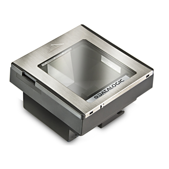
Omni-directional imaging scanner
Hide thumbs
Also See for Magellan 3300HSi:
- Product manual (216 pages) ,
- Product reference manual (216 pages) ,
- Quick reference manual (28 pages)
Table of Contents
Advertisement
Quick Links
Advertisement
Table of Contents

Related Manuals for Datalogic Magellan 3300HSi


Summary of Contents for Datalogic Magellan 3300HSi
- Page 1 Magellan 3300HSi Omni-Directional Imaging Scanner Quick Reference Guide...
- Page 2 Datalogic representative. Electronic versions may either be downloadable from the Data- logic website (www.datalogic.com) or provided on appropriate media. If you visit our website and would like to make comments or suggestions about this or other Datalogic publications, please let us know via the "Contact Datalogic" page.
-
Page 3: Table Of Contents
Table of Contents Quick Reference ..............1 Labeling and Nomenclature ..........1 Installation................2 How to Scan................3 Cleaning ................4 Troubleshooting ..............5 Productivity Index Reporting™ Option ....... 5 Scanner Push Button ........... 6 LED and Beeper Indicators ..........8 Error Codes ................. - Page 4 NOTES Magellan 3300HSi...
-
Page 5: Quick Reference
Use this guide to quickly complete your installation and begin using your scanner. For more details, including programming information, reference the Product Reference Guide (PRG), which is available for viewing and download from the Datalogic website listed on the back cover of this manual. Labeling and Nomenclature Figure 1. -
Page 6: Installation
Installation Connect the scanner to the host (terminal) using the interface (I/ F) cable as shown in Figure 2. A cable from an older existing installation can be re-used if it uses Power Off the Terminal (POT), unless it is a USB POT cable. If external power is used/ needed, plug the AC Adapter into the AC wall outlet, then connect it to the I/F cable as shown in ‘b’... -
Page 7: How To Scan
How to Scan The scanner is mounted flush with the counter to allow items to be slid or pushed over its top in the direction of the arrow as shown in Figure 3. Face the bar code toward the scanner or direc- tion of scan to optimize the scan rate. -
Page 8: Cleaning
Cleaning Exterior surfaces and scan windows exposed to spills, smudges or debris accumulation require periodic cleaning to assure best performance during scanning. Use a clean, lint-free cloth or paper towel dampened with a nonabrasive, mild, water-based window cleaner to wipe away stains, smudges, fingerprints, spills, etc. -
Page 9: Troubleshooting
If the scanner still does not function properly, consult the Product Reference Guide (PRG) or contact your local supplier or Datalogic Customer Support Services. a. Reading of the various bar code symbologies can be independently enabled or disabled in the scanner. -
Page 10: Scanner Push Button
Scanner Push Button The Scanner Push Button also performs multiple functions depending upon the duration of time it is pressed: Volume changes made using the Volume/Tone Push Button are lost when the scanner is pow- ered-down and are reset to the configured set- ting. - Page 11 Table 1. Scanner Push Button Functions PRESS FUNCTION COMMENT DURATION This mode allows system sup- port personnel to troubleshoot problems with the scanner and is used to determine if it can Scanner Diagnostics 4 Seconds read bar codes. Press the but- Mode ton for eight seconds or cycle power to exit Scanner Diagnos-...
-
Page 12: Led And Beeper Indicators
LED and Beeper Indicators The scanner’s beeper sounds and its green LED indicator illumi- nates to indicate various functions or errors on the scanner. The tables below list these indications. An exception to the behaviors listed in the tables is that the scanner’s functions are program- mable, and may or may not be turned on. - Page 13 Table 3. Beeper Functions BEEPER INDICATION COMMENT INDICATION The Power-On LED indication is a con- figurable feature which can be enabled Power On or disabled. When enabled, this beep Single beep Beep indicates the scanner has finished all its power up tests and is now ready for operation.
-
Page 14: Error Codes
Error Codes If an error is detected, the scanner will sound a long low tone (for three seconds) and flash its LED, indicating a failure. When this occurs, press the Scanner Push button to hear the error code. If it is configured to do so, the scanner will sound a series of beeps corresponding to the error code and/or flash its LED simultane- ous to the beeps. -
Page 15: Going Green
Going Green Thank you for using the bar code mask on the oppo- site side of this page. This manual has been format- ted to minimize the quantity of pages needed to provide interface programming bar codes available for this product. Quick Reference Guide... -
Page 16: Bar Code Mask
Bar Code Mask Cut a hole in this page and remove it from the man- ual as indicated to create a sleeve through which bar codes (starting on the following page) can be individ- ually viewed and scanned. It is important that only one bar code at a time be presented to the scanner. -
Page 17: Programming
Programming Upon completing the physical connection between the reader and its host, proceed directly to the Pro- gramming Bar Codes table below to locate the inter- face type the reader is connected to (for example: RS- 232, Keyboard Wedge, USB, etc.). Use the Bar Code Mask on the preceding page to iso- late the bar code you intend to scan. -
Page 18: Programming Bar Codes
START / END PROGRAMMING BAR CODES RS-232 Standard RS-232 Wincor-Nixdorf IBM 4683 Port 5B IBM 4683 Port 9B IBM 4683 Port 17 USB-OEM Magellan 3300HSi... - Page 19 START / END USB Keyboard USB COM Interface Keyboard Wedge A (PC/XT w/alternate Key Encoding) If other than Keyboard Wedge A with USA keyboard is needed, see the PRG or On Screen Programming for additional options. NOTE Quick Reference Guide...
- Page 20 NOTES Magellan 3300HSi...
-
Page 21: Datalogic Adc Limited Factory Warranty
The warranty period shall extend from the date of shipment from Data- logic for the duration published by Datalogic for the product at the time of purchase (War- ranty period). Datalogic warrants repaired hardware devices against defects in... -
Page 22: Risk Of Loss
THE POSSIBILITY OF SUCH DAMAGES. Risk of Loss Customer shall bear risk of loss or damage for product in transit to Datalogic. Datalogic shall assume risk of loss or damage for product in Datalogic’s possession. In the absence of specific written instructions for the return of product to Customer, Datalogic will select the carrier, but Datalogic shall not thereby assume any liability in connection with the return shipment. - Page 24 © 2010-2015 Datalogic ADC, Inc. • All rights reserved. • Datalogic and the Datalogic logo are registered trademarks of Datalogic S.p.A. in many countries, including the U.S.A. and the E.U. Datalogic ADC, Inc. 959 Terry Street Eugene |OR 97402...