Advertisement
Table of Contents
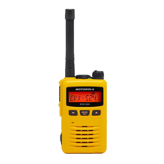
UHF Digital/Analog Transceiver
EVX-S24
Service Manual
Introduction
This manual provides the technical information necessary for servicing the EVX-S24 UHF Digi-
tal/Analog Transceiver.
Servicing this equipment requires expertise in handing surface-mount chip components. At-
tempts by non-qualifi ed persons to service this equipment may result in permanent damage not
covered by the warranty, and may be illegal in some countries.
Two PCB layout diagrams are provided for each double-sided board in this transceiver. Each side
of the board is referred to by the type of the majority of components installed on that side ("Side
A" or "Side B"). In most cases one side has only chip components (surface-mount devices), and
the other has either a mixture of both chip and leaded components (trimmers, coils, electrolytic
capacitors, ICs, etc.), or leaded components only.
As described in the pages to follow, the advanced microprocessor design of the EVX-S24 Trans-
ceiver allows a complete alignment of this transceiver to be performed without opening the case
of the radio; all adjustments can be performed from the front panel, using the "Alignment Mode"
menu.
While we believe the information in this manual to be correct, Vertex Standard assumes no li-
ability for damage that may occur as a result of typographical or other errors that may be present.
Your cooperation in pointing out any inconsistencies in the technical information would be ap-
preciated.
This transceiver is assembled using Pb (lead) free solder, based on the RoHS specifi cation.
Only lead-free solder (Alloy Composition: Sn-3.0Ag-0.5Cu) should be used for repairs performed on this apparatus.
The solder stated above utilizes the alloy composition required for compliance with the lead-free specifi cation, and
any solder with the above alloy composition may be used.
Specifi cations................................................................................................................................................................. 2
Exploded View & Miscellaneous Parts ....................................................................................................................... 4
Parts List ....................................................................................................................................................................... 5
Block Diagram .............................................................................................................................................................. 6
Circuit Description ....................................................................................................................................................... 8
Alignment ...................................................................................................................................................................... 9
Main Unit (FR028210D) Circuit Diagram .............................................................................................................. 18
Display Unit (FR028310A) Circuit Diagram .......................................................................................................... 20
EVX-S24 UHF Digital/Analog Transceiver Service Manual
Vertex Standard LMR, Inc.
Important Note
Contents
©2016 Vertex Standard LMR, Inc.
EC146U90B
1
Advertisement
Table of Contents

Related Manuals for Vertex Standard EVX-S24


Summary of Contents for Vertex Standard EVX-S24
-
Page 1: Table Of Contents
(trimmers, coils, electrolytic capacitors, ICs, etc.), or leaded components only. As described in the pages to follow, the advanced microprocessor design of the EVX-S24 Trans- ceiver allows a complete alignment of this transceiver to be performed without opening the case of the radio;... -
Page 2: Specifi Cations
–36 dBm @ < = 1 GHz, –30 dBm @> 1 GHz Conducted Spurious Emissions: FM Hum & Noise: 45 dB (25 kHz) 40 dB (12.5 kHz) Audio Distortion: <5% @1 kHz Specifi cations subject to change without notice or obligation. EVX-S24 UHF Digital/Analog Transceiver Service Manual... - Page 3 –36 dBm @ < = 1 GHz, –30 dBm @> 1 GHz Conducted Spurious Emissions: FM Hum & Noise: 45 dB (25 kHz) 40 dB (12.5 kHz) Audio Distortion: <5% @1 kHz Specifi cations subject to change without notice or obligation. EVX-S24 UHF Digital/Analog Transceiver Service Manual...
-
Page 4: Exploded View & Miscellaneous Parts
U9900309 Y-RECESS TAPTITE-B 2X22SUS B CB7122000 U9900311 Y-RECESS TAPTITE-B 2X13NI BATTERY COVER ASSY ( YEL ) U9900313 Y-RECESS SCREW M2X16.5NI CB7123000 Non-designated parts are available only as part of a designated assembly. EVX-S24 UHF Digital/Analog Transceiver Service Manual... -
Page 5: Parts List
TACT SWITCH SKRMABE010 N5090172 ( 133 ) GROUBD PLATE RA1642300 ( x3 pcs ) PAN HEAD TAPTITE-B 2X5 #2 U9900307 When replace a chip fuse, use the part of the same type and value. EVX-S24 UHF Digital/Analog Transceiver Service Manual... -
Page 6: Block Diagram
Block Diagram EVX-S24 UHF Digital/Analog Transceiver Service Manual... - Page 7 Block Diagram EVX-S24 UHF Digital/Analog Transceiver Service Manual...
-
Page 8: Circuit Description
The main constitution product of the PLL is equipped all with in the custom IC Q1046 (RODINIA), so that all pro- cessing regarding the frequency control is performed in the custom IC Q1046 (RODINIA). EVX-S24 UHF Digital/Analog Transceiver Service Manual... -
Page 9: Alignment
Because of the BTL (Bridged Trans Less) Amplifi er cir- instructions regarding repair. Authorized Vertex Standard cuit used in the EVX-S24, do not connect earth side of service technicians realign all circuits and make complete the speaker leads to chassis “ground”. -
Page 10: Test Setup
CB000262A01 Micro USB Programming Cable Sampling Coupler 50-ohm Inline Computer Transceiver USB Port Dummy Load Wattmeter ( CE157 ) Micro USB Jack Battery Terminal Deviation Power Supply Meter 3.7 VDC Frequency Counter EVX-S24 UHF Digital/Analog Transceiver Service Manual... - Page 11 4. After getting the desired frequency, click the “PTT” but- ton or press the “SPACE” bar to stop transmitting. 5. Click the “OK” button to fi nish the frequency alignment and save the data. EVX-S24 UHF Digital/Analog Transceiver Service Manual...
- Page 12 (ADJ Type) located at the bottom of the screen, as needed. Basic: “Low-edge / band center / high-edge” and se- lect the channel for alignment (Default). Single: Alignment value changes only on the selected channel. All Freq: Alignment value changes on all channels. EVX-S24 UHF Digital/Analog Transceiver Service Manual...
- Page 13 Basic: “Low-edge / band center / high-edge” and se- lect the channel for alignment (Default). Single: Alignment value changes only on the selected channel. All Freq: Alignment value changes on all channels. EVX-S24 UHF Digital/Analog Transceiver Service Manual...
- Page 14 You may align the deviation level by any CTCSS tone fre- quency (default: 300.0 Hz) by changing the value of the “CTCSS Freq” box located at the bottom of the screen, if needed. EVX-S24 UHF Digital/Analog Transceiver Service Manual...
- Page 15 You may align the deviation level by any DTMF tone (de- fault: “0”, available selection: “0” - “9”, “A” - “D”, “E(*)”, and “F(#)”) by changing the value of the “DTMF Code” box located at the bottom of the screen, if needed. EVX-S24 UHF Digital/Analog Transceiver Service Manual...
- Page 16 Tone Deviation Alignment” window. 2. Entering the desired value in the “New” box from the computer’s keyboard. 3. Click the “OK” button to fi nish the Sequential Tone De- viation alignment and save the data. EVX-S24 UHF Digital/Analog Transceiver Service Manual...
- Page 17 Alignment OWNLOAD LIGNMENT ATA AND XIT FROM THE LIGNMENT Press the “OK” button, then the Alignment Data will be downloaded (saved) to the transceiver and Exit from the Alignment Mode. EVX-S24 UHF Digital/Analog Transceiver Service Manual...
-
Page 18: Main Unit (Fr028210D) Circuit Diagram
Main Unit ( FR028210D ) Circuit Diagram ( RF Section ) EVX-S24 UHF Digital/Analog Transceiver Service Manual... - Page 19 Main Unit ( FR028210D ) Circuit Diagram ( CONTROL Section ) EVX-S24 UHF Digital/Analog Transceiver Service Manual...
-
Page 20: Display Unit (Fr028310A) Circuit Diagram
Display Unit ( FR028310A ) Circuit Diagram EVX-S24 UHF Digital/Analog Transceiver Service Manual... - Page 21 No portion of this manual may be reproduced without the per- mission of Vertex Standard LMR, Inc. Vertex Standard is a trademark of Vertex Standard LMR, Inc. All other trademarks are the property of their respective owners. ©2016 Vertex Standard LMR, Inc.