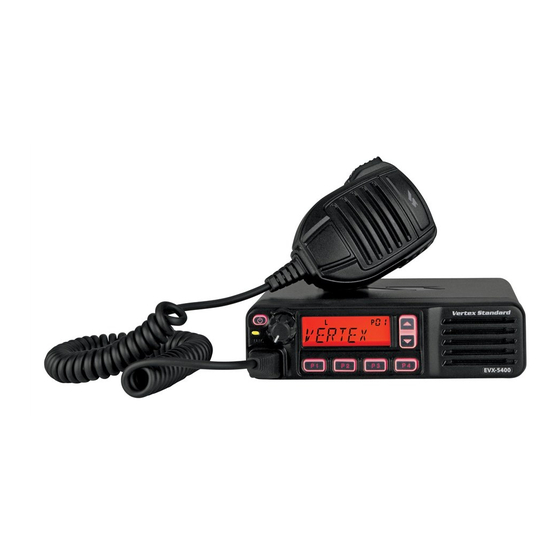
Vertex Standard EVX-5300 Service Manual
Uhf digital/analog mobile transceiver
Hide thumbs
Also See for EVX-5300:
- Operating manual (45 pages) ,
- Operating manual (33 pages) ,
- Operating manual (21 pages)
Table of Contents
Advertisement
Quick Links
UHF Digital/Analog
Mobile Transceiver
EVX-5300/-5400
Service Manual
EVX-5300
Introduction
This manual provides technical information necessary for servicing the EVX-5300/-5400 UHF Digital/Analog Mobile Trans-
ceiver.
Servicing this equipment requires expertise in handling surface-mount chip components. Attempts by non-qualiied persons to
service this equipment may result in permanent damage not covered by the warranty, and may be illegal in some countries.
Two PCB layout diagrams are provided for each double-sided circuit board in the transceiver. Each side of is referred to by the
type of the majority of components installed on that side ("leaded" or "chip-only"). In most cases one side has only chip com-
ponents, and the other has either a mixture of both chip and leaded components (trimmers, coils, electrolytic capacitors, ICs,
etc.), or leaded components only.
As described in the pages to follow, the advanced microprocessor design of the EVX-5300/-5400 allows a complete alignment
of this transceiver to be performed without opening the case of the radio; all adjustments can be performed from the personal
computer, using with the Vertex Standard FIF-12 USB Programming Interface and CE142 Software.
While we believe the technical information in this manual to be correct, Vertex Standard assumes no liability for damage that
may occur as a result of typographical or other errors that may be present. Your cooperation in pointing out any inconsistencies
in the technical information would be appreciated.
This transceiver is assembled using Pb (lead) free solder, based on the RoHS speciication.
Only lead-free solder (Alloy Composition: Sn-3.0Ag-0.5Cu) should be used for repairs performed on this apparatus.
The solder stated above utilizes the alloy composition required for compliance with the lead-free speciication, and any
solder with the above alloy composition may be used.
USA/EXP Models ...................................... 2
EU Model ................................................... 3
DSUB 15-pin Accessory Connector ............. 4
Exploded View & Miscellaneous Parts ....... 5
Parts List ........................................................ 6
Block Diagram ............................................... 8
Circuit Description ..................................... 10
EVX-5300/-5400 UHF Service Manual
Important Note
Contents
Alignment..................................................... 12
MAIN Unit ( FR026490A: TYPE "G6" ) ...... 23
MAIN Unit ( FR024860B: TYPE "G7" ) ...... 25
Vertex Standard LMR, Inc.
©
2014 Vertex Standard LMR, Inc.
EC114U90E
EVX-5400
1
Advertisement
Table of Contents

Related Manuals for Vertex Standard EVX-5300


Summary of Contents for Vertex Standard EVX-5300
-
Page 1: Table Of Contents
Vertex Standard FIF-12 USB Programming Interface and CE142 Software. While we believe the technical information in this manual to be correct, Vertex Standard assumes no liability for damage that may occur as a result of typographical or other errors that may be present. Your cooperation in pointing out any inconsistencies in the technical information would be appreciated. -
Page 2: Speciications Usa/Exp Models
Frequency Range: 403-470 MHz (Type “G6”) 450-520 MHz (Type “G7”) (USA Model: 450-512 MHz) Channel / Group: 8 Channel / 1 Group (EVX-5300) 512 Channel / 32 Group (EVX-5400) Channel Spacing: 12.5 / 25 kHz (Analog) (USA Model: 12.5 kHz) 12.5 kHz (Digital) -
Page 3: Eu Model
Speciications ( EU Model ) General Frequency Range: 403-470 MHz Channel / Group: 8 Channel / 1 Group (EVX-5300) 512 Channel / 32 Group (EVX-5400) Channel Spacing: 12.5 / 20 / 25 kHz (Analog) 12.5 kHz (Digital) Emission Type: 16K0F3E / 14K0F3E / 11K0F3E (Analog) 7K60F1E / 7K60FXE (Digital: 12.5 kHz Voice) -
Page 4: Dsub 15-Pin Accessory Connector
600-ohm. Pin 8: IGN (Ignition Sense feature) Pin 3: AF GND The EVX-5300/-5400 may be automatically be switched to the STND-BY mode when the vehicle’s ignition key is Ground for all logic levels and power supply return. turned on. Maximum current is 20 mA. -
Page 5: Exploded View & Miscellaneous Parts
SHIELD CASE COVER (TOP) EVX-5300 FRONT PANEL ASSY TYPE “G6”, 25W: G1095437 (RA30H3847M1A) TYPE “G7”, 25W: G1095438 (RA30H4452M1A) EVX-5300 FRONT PANEL ASSY ( C omponent TYPE “G6”, 45W: G1095428 (RA60H3847M1A) FRONT PANEL ASSY ( 8ch ) TYPE “G7”, 45W: G1095429 (RA60H4452M1A) -
Page 6: Parts List
CB6728000: EVX-5300, TYPE “G7”, 45W Please conirm the irmware version when replace the MAIN-2 UNIT CB6729000: EVX-5300, TYPE “G7”, 25W CB6730000: EVX-5400, TYPE “G7”, 45W CB6731000: EVX-5400, TYPE “G7”, 25W EVX-5300 FRONT PANEL ASSY ( CB6649000 ) FRONT PANEL ASSY RA1492800 NAME PLATE EVX-5300... - Page 7 32.768kHz 4809995L18 32.768KHZ H0103407 X 4002 TCXO 19.2MHz TTS27NSC-A7 19.2MHZ H9501380 XF4001 XTAL FILTER DSF753SDF 50.85MHZ H1102479 FRONT-A UNIT ( FR024850C: EVX-5300 ) Electrical & Mechanical Parts DS2001 ELS-512SURWA/S530-A3 G2090796 J 2001 CONNECTOR 43090-1505 P1091319 J 2002 CONNECTOR 52793-2070 P1091408...
-
Page 8: Block Diagram
Block Diagram MAIN Unit/MAIN-2 Unit ( EVX-5300/-5400 ) EVX-5300/-5400 UHF Service Manual... - Page 9 Block Diagram FRONT-A Unit ( EVX-5300 ) FRONT-B Unit ( EVX-5400 ) EVX-5300/-5400 UHF Service Manual...
-
Page 10: Circuit Description
The speech signal from the external microphone which con- Low-pass ilter, antenna switching diode D1014, D1016 (both nected to the J2001 (EVX-5300) or J3001 (EVX-5400) is JDP2S12CR), and the 1st RF attenuator Q1037 (SKY12338), supplied to the AF ampliier Q2005 (NJM2125: EVX-5300) - Page 11 1st mixer Q1053 (AK1220) in case of the reception. In the transmission, the output is modulated to the FM (or digital) in the custom IC Q1070 (RFIC), and then supplied to the transmitter section described previously. EVX-5300/-5400 UHF Service Manual...
-
Page 12: Alignment
Alignment Introduction Required Test Equipment The EVX-5300/-5400 has been aligned at the factory for the r Radio Tester with calibrated output level at 600 MHz speciied performance across the entire frequency range spec- r In-line Wattmeter with 5% accuracy at 600 MHz iied. - Page 13 During alignment, you may select the value among dBµV, µV (EMF or PD), or dBm by the “UNIT” box. When perform the RX Tune and SQL alignment, the RF level shows this unit according to this setting. EVX-5300/-5400 UHF Service Manual...
- Page 14 4. After getting the desired frequency, click the “PTT” button or press the “SPACE” bar to stop transmitting. 5. Click the “OK” button to finish the frequency alignment and save the data. EVX-5300/-5400 UHF Service Manual...
- Page 15 (ADJ Type) located at the bottom of the screen, as needed. Basic: “Low-edge / band center / high-edge” and select the channel for alignment (Default). Single: Alignment value changes only on the selected chan- nel. All Freq: Alignment value changes on all channels. ê EVX-5300/-5400 UHF Service Manual...
- Page 16 Normal RSSI Level (Wide/Narrow) Tight RSSI Level (Wide/Narrow) Other alignment items has not extra step; only one step proce- dure. ê 6. Click the “OK” button, then the data will be saved and the alignment is inished. EVX-5300/-5400 UHF Service Manual...
- Page 17 (ADJ Type) located at the bottom of the screen, as needed. Basic: “Low-edge / band center / high-edge” and select the channel for alignment (Default). Single: Alignment value changes only on the selected chan- nel. All Freq: Alignment value changes on all channels. EVX-5300/-5400 UHF Service Manual...
- Page 18 Type) located at the bottom of the screen, as needed. Basic: “Low-edge / band center / high-edge” and select the channel for alignment (Default). Single: Alignment value changes only on the selected chan- nel. All Freq: Alignment value changes on all channels. EVX-5300/-5400 UHF Service Manual...
- Page 19 (ADJ Type) located at the bottom of the screen, as needed. ê Basic: “Low-edge / band center / high-edge” and select the channel for alignment (Default). Single: Alignment value changes only on the selected chan- nel. All Freq: Alignment value changes on all channels. EVX-5300/-5400 UHF Service Manual...
- Page 20 5. Click the “OK” button to inish the DCS Deviation alignment and save the data. You may align the deviation level by any DCS code (default: 532) by changing the value of the “DCS Code” box located at the bot- tom of the screen, if needed. EVX-5300/-5400 UHF Service Manual...
- Page 21 Data” box from the computer’s keyboard 4. After getting the desired deviation, click the “PTT” button or press the “SPACE” bar to stop transmitting. 5. Click the “OK” button to inish the MSK Deviation alignment and save the data. EVX-5300/-5400 UHF Service Manual...
- Page 22 1. Press the “Seq Tone” button to open the “Sequential Tone De- viation Alignment” window. 2. Entering the desired value in the “New” box from the comput- er’s keyboard. 3. Click the “OK” button to inish the Sequential Tone Deviation alignment and save the data. ê EVX-5300/-5400 UHF Service Manual...
-
Page 23: Circuit Diagram
MAIN Unit ( FR026490A: TYPE “G6” ) Circuit Diagram ( RF & AF Section ) EVX-5300/-5400 UHF Service Manual... - Page 24 MAIN Unit ( FR026490A: TYPE “G6” ) Circuit Diagram ( Control Section ) EVX-5300/-5400 UHF Service Manual...
-
Page 25: Main Unit ( Fr024860B: Type "G7" )
MAIN Unit ( FR024860B: TYPE “G7” ) Circuit Diagram ( RF & AF Section ) EVX-5300/-5400 UHF Service Manual... - Page 26 MAIN Unit ( FR024860B: TYPE “G7” ) Circuit Diagram ( Control Section ) EVX-5300/-5400 UHF Service Manual...
-
Page 27: Main-2 Unit ( Fr026490A: Type "G7" )
MAIN-2 Unit ( FR026490A: TYPE “G7” ) Circuit Diagram ( RF & AF Section ) EVX-5300/-5400 UHF Service Manual (for LMR) - Page 28 MAIN-2 Unit ( FR026490A: TYPE “G7” ) Circuit Diagram ( Control Section ) EVX-5300/-5400 UHF Service Manual (for LMR)
-
Page 29: Front-A Unit ( Fr024850C: Evx-5300 )
FRONT-A Unit ( FR024850C: EVX-5300 ) Circuit Diagram EVX-5300/-5400 UHF Service Manual... -
Page 30: Front-B Unit ( Fr025010C: Evx-5400 )
FRONT-B Unit ( FR025010B: EVX-5400 ) Circuit Diagram EVX-5300/-5400 UHF Service Manual... - Page 31 Copyright 2014 Vertex Standard LMR, Inc. All rights reserved. No portion of this manual may be reproduced without the permission of Vertex Standard LMR, Inc. EVX-5300/-5400 UHF Service Manual...