Table of Contents
Advertisement
Quick Links
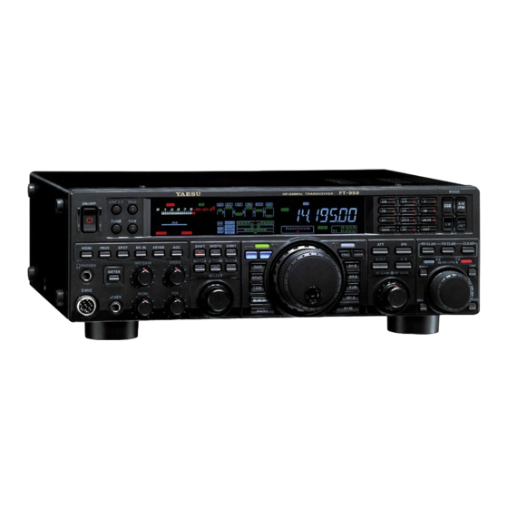
FT-950
Operating Manual
About This Manual . . .
The FT-950 is a leading-edge transceiver with a number of new and exciting features,
some of which may be unfamiliar to you. In order to gain the most enjoyment and
operating efficiency from your FT-950, we recommend that you read this manual in its
entirety, and keep it handy for reference as you explore the many capabilities of your
new transceiver.
Before using your FT-950, be sure to read and follow the instructions in the "Before You
Begin" section of this manual.
General Description
Congratulations on the purchase of your Yaesu amateur transceiver! Whether this is
your first rig, or if Yaesu equipment is already the backbone of your station, rest
assured that your transceiver will provide many hours of operating pleasure for years
to come.
The FT-950 is an elite-class HF transceiver providing exceptional performance both on
transmit and receive. The FT-950 is designed for the most competitive operating
situations, whether you primarily operate in contest, DX, or digital-mode
environments.
Built on the foundation of the popular FTdx9000 transceiver, and carrying the proud
tradition of the FT-1000 series, the FT-950 provides up to 100 Watts of power output on
SSB, CW, and FM (25 Watts AM carrier). Digital Signal Processing (DSP) is utilized
throughout the design, providing leading-edge performance on both transmit and
receive.
Available as an option for the FT-950 is the Data Management Unit (DMU-2000),
which provides extensive display capabilities via a user-supplied computer monitor.
Included are Band Scope, Audio Scope, X-Y Oscilloscope, World Clock, Rotator Control,
and extensive transceiver status displays, in addition to station logging capability.
For exceptional protection from strong nearby incoming signals, the optional RF
µTuning Kits may be connected via the rear panel, providing extraordinarily sharp
selectivity to protect your receiver from close-in interference on a crowded band.
Vertex Standard Co., Ltd.
1
Advertisement
Table of Contents

Related Manuals for Vertex Standard FT-950


Summary of Contents for Vertex Standard FT-950
- Page 1 Before using your FT-950, be sure to read and follow the instructions in the “Before You Begin” section of this manual. General Description...
- Page 2 Optimization) utilizing direct feed to the first mixer, and/or three levels of RF attenuation in 6-dB steps. The FT-950 receiver utilizes DSP filtering, incorporating many of the features of the 9000, such as Variable Bandwidth, IF Shift, and Passband Contour tuning.
-
Page 3: Table Of Contents
We greatly appreciate your investment in the FT-950, and we look forward to helping you get the most out of your new transceiver. Please feel free to contact your nearest dealer, or one of Vertex Standard’s national headquarters offices, for technical advice, interfacing... - Page 4 P.BACK (Audio Playback) from Main (VFO-A) Receiver P.BACK feature from the optional FH-2 Remote Control Keypad “MY Bands” Operation Band Stack Operation C.S (Custom Switch) Rotator Control Functions More Frequency Navigation Techniques Keyboard Frequency Entry Using the [SUB VFO-B] knob Vertex Standard Co., Ltd.
- Page 5 Adjusting the SSB Transmitted Bandwidth (SSB Mode) Parametric Microphone Equalizer (SSB/AM mode) 71 Transmitter Convenience Features 72 Voice Memory (SSB/AM/FM modes) Voice Memory Operation from the optional FH-2 Remote Control Keypad VOX (Automatic TX/RX Switching using Voice Control: SSB/AM/FM Modes) Vertex Standard Co., Ltd.
- Page 6 FM Mode Operation Basic Operation 92 Repeater Operation Memory Operation Convenient Memory functions QMB (Quick Memory Bank) Standard Memory Operation Memory Storage 96 Memory Channel Recall 96 Checking a Memory Channel’s Status Erasing Memory Channel Data Vertex Standard Co., Ltd.
- Page 7 DISPLAY Group 112 DVS Group KEYER SETUP Group GENERAL Group S IF SFT Group 116 MODE-AM Group MODE-CW Group MODE-DAT Group MODE-FM Group MODE-RTY Group MODE-SSB Group RX AUDIO Group RX DSP Group SCOPE Group TUNING Group 124 Vertex Standard Co., Ltd.
-
Page 8: Accessories & Options
RF µTuning Kit A For 160 m Band RF µTuning Kit B For 80/40 m Bands RF µTuning Kit C For 30/20 m Bands FH-2 Remote Control Keypad DVS-6 Digital Voice Memory Unit Before You Begin Vertex Standard Co., Ltd. -
Page 9: Extending The Front Feet
AC voltage, reverse polarity DC, or DC voltage outside the specified range of 13.8 V ±10 %. When replacing fuses, be certain to use a fuse of the proper rating. The FT-950 requires a 25 A blade fuse. -
Page 10: Resetting The Microprocessor
Important Note: When the optional µTuning Kit is connected to the FT-950, disconnect the all cables from the µTuning Kit then perform the Full Reset. Installation and Interconnections Antenna Considerations The FT-950 is designed for use with any antenna system providing a 50 Ohm resistive Vertex Standard Co., Ltd. -
Page 11: About Coaxial Cable
Amateur bands, and an external wide-range antenna coupler must be used with this antenna type. Any antenna to be used with the FT-950 must, ultimately, be fed with 50 Ohm coaxial cable. Therefore, when using a “balanced” antenna such as a dipole, remember that a balun or other matching/balancing device must be used so as to ensure proper antenna performance. -
Page 12: Connection Of Antenna And Power Cables
Do not position this apparatus in a location with direct exposure to sunshine. Do not position this apparatus in a location exposed to dust and/or high humidity. Ensure adequate ventilation around this apparatus, so as to prevent heat build-up and possible reduction of performance due to high heat. Vertex Standard Co., Ltd. -
Page 13: Connection Of Microphone And Headphone
Connection of Microphone and Headphone Key, Keyer, and Computer-Driven Keying Interconnections The FT-950 includes a host of features for the CW operator, the functions of which will be detailed in the “Operation” section later. Besides the built-in Electronic Keyer, two key jacks are provided, one each on the front and rear panels, for convenient connection to keying devices. -
Page 14: Interfacing To Other Linear Amplifiers
About the CONTROL Cable The VL-1000 may be operated with the FT-950 whether or not the CONTROL Cable is connected; however, the CONTROL Cable allows you to tune up the amplifier automatically by just pressing the [F SET] or [TUNE] key on the VL-1000, so as to transmit a carrier for tuning purposes. -
Page 15: Front Panel Controls & Switches
Block Diagram Display in the display. 3. [TUNE] Switch This is the on/off switch for the FT-950’s Automatic Antenna Tuner. Pressing this button momentarily places the antenna tuner in line between the transmitter final amplifier and the antenna jack (“TUNER” icon will appear in the display). - Page 16 Audio Scope/Oscilloscope page to help you adjust the setting of the compression level of the Speech Processor for optimum performance using your voice and microphone. 8. [SPOT] Switch This button turns on the CW receiver spotting tone; by matching the SPOT tone to that Vertex Standard Co., Ltd.
- Page 17 3-contact plugs. When a plug is inserted, the loudspeaker is disabled. Note: When wearing headphones, we recommend that you turn the AF Gain levels down to their lowest settings before turning power on, to minimize the impact on your hearing caused by audio “pops” during switch-on. Vertex Standard Co., Ltd.
- Page 18 “Bug,” “straight key”, or computer keying interface operation via Menu item “037 A1A F-TYPE” (see page ??). There is another jack with the same name on the rear panel, and it may be configured independently for Internal Keyer or Vertex Standard Co., Ltd.
- Page 19 Pressing this button allows you to adjust the center frequency of the µ-Tuning filter passband using the [SELECT] knob, when the optional RF µTuning Kit is connected. While activated, the LED inside this button glows orange. 25. [CLEAR] Switch Vertex Standard Co., Ltd.
- Page 20 When the transceiver receives the VFO-A frequency, pressing this button momentarily will mute the receiver, and the indicator will blink. Pressing the button once more will restore receiver operation, and the indicator will glow green steadily. 28. QMB (Quick Memory Bank) Switches Vertex Standard Co., Ltd.
- Page 21 To program a Menu selection as the short-cut, press the [MENU] button to enter the Menu, then select the Menu item you want to set as the short-cut. Now press and hold in the [C.S] button for two seconds; this will lock in the selected Menu item as the short-cut. Vertex Standard Co., Ltd.
- Page 22 Pressing this button will increase or decrease the tuning rate of the Main Tuning Dial knob (for VFO-A frequency) and the [CLA/VFO-B] knob (for VFO-B frequency) a factor of ten, as mentioned in the previous section. When this function is activated, the “FAST” icon appears in the display. Vertex Standard Co., Ltd.
- Page 23 Holding this button in for two seconds copies the data from the currently-selected memory to the VFO-A, as two beeps sound. Previous data in the VFO-A will be overwritten. 46. [A>M] Switch Pressing this button momentarily displays the contents of the currently-selected memory channel for 10 seconds. Vertex Standard Co., Ltd.
- Page 24 Block Diagram Display on the display. 51. [R.FLT] (Roofing Filter) Switch This button selects the bandwidth of the receiver’s first IF Roofing Filter. Available selections are 3 kHz, 6 kHz, 15 kHz, or Auto, and the selected bandwidth appears in Vertex Standard Co., Ltd.
- Page 25 Press this button once more to return the transmitter to the original frequency; the Clarifier offset will still be present, though, in case you want to use it again. To cancel the Clarifier offset, press the [CLEAR] button. Vertex Standard Co., Ltd.
- Page 26 63. [CLAR/VFO-B] Knob This knob usually tunes the Clarifier offset frequency up to ±9.99 kHz, otherwise, this knob is used to adjust the status of the functions depending on the five buttons located around this knob. Vertex Standard Co., Ltd.
-
Page 27: Display Indications
Indicates the RF Power Output, from 0 to 150 Watts on transmit. Advice: The S and PO meters can be provided the Peak-hold function via the Menu item “007 DISP PKH S” and “008 DISP PKH PO”. Vertex Standard Co., Ltd. - Page 28 Contest Keyer is recording your CW keying. 13. PLAY This indicator appears while the optional Voice Memory Unit is playing back the recorded your voice message, or the Contest Keyer is playing back the recorded CW keying. Vertex Standard Co., Ltd.
- Page 29 The peak position of the CONTOUR Filter is depicted graphically here when the CONTOUR Filter is activated. 18. NOTCH The null position of the IF Notch Filter is depicted graphically here when the IF Notch Filter is activated. 19. WIDTH Indicates the bandwidth of the DSP IF filter. Vertex Standard Co., Ltd.
- Page 30 This is a tuning scale that, as configured from the factory, provides a visual CW tuning indication of the incoming signal’s offset from your transceiver’s CW carrier frequency, as programmed by the relative clarifier offset, or the peak position of the optional Vertex Standard Co., Ltd.
-
Page 31: Rear Panel
29. MR This indicator appears when the FT-950 is in the Memory Recall mode. 30. MT This indicator appears when the FT-950 is in the Memory Tune mode to indicate that the memory contents have been temporarily changed. 31. Multi-Display Window This window displays either the Clarifier offset or Memory Channel Number. - Page 32 The same line is available at the RTTY/PKT jack for TNC control. Open-circuit voltage is +13.5 VDC, and closed-circuit current is 5 mA. 10. REC Jack This RCA jack provides low-level receiver audio output and transmit audio, for Vertex Standard Co., Ltd.
- Page 33 11. REM (REMOTE) Jack By plugging in the optional FH-2 Remote Control Keypad to this gold-plated jack, direct access to the FT-950 CPU is provided for control functions such as contest memory keying, plus frequency and function control. 12. EXT SPKR Jack This 3.5-mm, 2-pin jack provides variable audio output for an external loudspeaker.
-
Page 34: Basic Operation: Receiving On Amateur Bands
VFO-A receiver is temporarily muted. Just press the [(VFO-A)RX] Indicator/Switch once more to restore VFO-A receiver operation. 6. Press the [BAND] button corresponding to the Amateur band on which you wish to begin operation. Advice: Vertex Standard Co., Ltd. - Page 35 One-touch selection of each Amateur band between 1.8 and 50 MHz is provided. The FT-950 utilizes a triple band-stack VFO selection technique, which permits you to store up to three favorite frequencies and modes onto each band’s VFO register. For example, you may store one frequency each on 14 MHz CW, RTTY, and USB, then recall these VFOs by successive, momentary presses of the [14] MHz band button.
-
Page 36: Operation On 60-Meter (5 Mhz) Band (U.s. Version Only)
(see page ??). Operation on 60-Meter (5 MHz) Band (U.S. version only) The FT-950 includes the capability for transmission and reception on the five spot frequencies assigned to the Amateur Service in the United States. To operate on the 5 MHz band: Press the [V/M] button once to enter the “Memory”... - Page 37 (the Clarifier does not affect the VFO-B, however). The four small numbers on the Multi-Display Window show the current Clarifier offset. The Clarifier controls on the FT-950 are designed to allow you to preset an offset (up to 9.990 kHz) without ±...
-
Page 38: Lock
Advice: Press the [SELECT] knob to toggle the Menu item display between “005 DISP” and “DIM VFD”. Rotate the [CLAR/VFO-B] knob to select desired illumination level. Press and hold in the [MENU] button for two seconds to save the new setting and exit to normal operation. Convenience Features Vertex Standard Co., Ltd. -
Page 39: My Bands" Operation
Rotate the [SELECT] knob to select Menu item “090 TUN MY BAND.” Advice: Press the [SELECT] knob to toggle the Menu item display between “090 TUN” and “MY BAND”. skip Rotate the [CLAR/VFO-B] knob to choose a band that you wish to (omit) from Vertex Standard Co., Ltd. -
Page 40: Band Stack Operation
Advice: The “My Band” feature affects both the VFO-A and VFO-B. Band Stack Operation The FT-950 utilizes a triple band-stack VFO selection technique, that permits you to store up to three favorite frequencies and modes onto each band’s VFO register. For example, you may store one frequency each on 14 MHz CW, RTTY, and USB, then recall these VFOs by successive, momentary presses of the [14] MHz band button. -
Page 41: Custom Switch)
When using a YAESU model G-800DXA, G-1000DXA, or G-2800DXA rotator (not supplied), it is possible to control it from the front panel of the FT-950. Press and hold in the [ENT] button (one of the [BAND] Switch) for two seconds. -
Page 42: More Frequency Navigation Techniques
Menu item “011 DISP RTR STU” must be set to “180”. If not set properly the FT-950 display will not show the correct direction. When the rotator control indicator needle does not indicate the precise antenna direction, adjusts the indicator needle precisely to the antenna direction via the Menu item “012 DISP RTR ADJ”. -
Page 43: Receiver Operation (Front End Block Diagram)
STEP” and “088 TUN FM STEP.” Receiver Operation (Front End Block Diagram) The FT-950 includes a wide range of special features to suppress the many types of interference that may be encountered on the HF bands. However, real world interference conditions are constantly changing, so optimum setting of the controls is somewhat of an art, requiring familiarity with the types of interference and the subtle effects of some of the controls. -
Page 44: Att
When extremely strong local signals or high noise can still degrade reception, you can use the [ATT] button to insert 6, 12, or 18-dB of RF attenuation in front of the RF amplifier. Vertex Standard Co., Ltd. - Page 45 3.5 and 7 MHz bands. The MTU-30/20 covers 10.1 and 14 MHz bands. When any (or all) of the three optional units are connected, they will be automatically adjusted to center on your operating frequency. Vertex Standard Co., Ltd.
- Page 46 Amateur Radio transceiver. The RF selectivity provided by µ-Tune can be of tremendous value in ensuring quiet, intermod-free reception even in the most crowded bands on a contest weekend. The µ-Tune filters provide RF Vertex Standard Co., Ltd.
- Page 47 Bypasses the RF preamplifier, yielding direct feed to the first mixer. The selected receiver RF preamplifier will be indicated in the IPO column of the Block Diagram Display on the display. Advice: The IPO selection will be memorized independently on each VFO stack of the Vertex Standard Co., Ltd.
-
Page 48: R.flt (Roofing Filters)
When the Roofing filter mode is set to “AUTO” and the Noise Blanker is turned On, the Roofing Filter bandwidth will automatically be set to 15 kHz, as this setting provides the most effective noise blanking. However, you still may override the Vertex Standard Co., Ltd. - Page 49 IF Noise Blanker (NB) Operation The FT-950 includes an effective IF Noise Blanker, which can significantly reduce noise caused by automotive ignition systems. Press the [NB] button momentarily to reduce short-duration pulse noise such as from switching transients, automobile ignitions and power lines.
-
Page 50: Contour Control Operation
Contour control. Not only can you see the effect of the null/peak of the Contour system, but you also can see the position of the null/peak with respect to frequency components of interest on the incoming signal. You may then observe (on the Audio Vertex Standard Co., Ltd. -
Page 51: If Shift Operation (Ssb/Cw/Rtty/Pkt/Am Modes)
Rotate the [SHIFT] knob to the left or right to reduce the interference. Press the [CLEAR] button to move the filter passband to center. Advice: The center position of the IF passband will be memorized independently on Vertex Standard Co., Ltd. -
Page 52: Width (If Dsp Bandwidth) Tuning (Ssb/Cw/Rtty/Pkt Modes)
The default bandwidths, and total bandwidth adjustment range, will vary according to the operating mode: SSB Mode: 1.8 kHz ~ 3.0 kHz (default: 2.4 kHz). CW Mode: 500 Hz ~ 2.4 kHz (default: 2.4 kHz) RTTY/PKT Modes: 500 Hz ~ 2.4 kHz (default: 500 Hz) Vertex Standard Co., Ltd. -
Page 53: Using If Shift And Width Together
When the narrow bandwidth is selected, the “NAR” icon will appear in the display. Even if the [NAR] button has been pressed so as to engage the narrow filter, you may adjust the IF bandwidth by rotating the [SELECT(WIDTH)] knob (requires Vertex Standard Co., Ltd. -
Page 54: If Notch Filter Operation (Ssb/Cw/Rtty/Pkt/Am Modes)
The performance of the IF NOTCH filter is shown in Figure (A), where the effect of rotation of the [SELECT(NOTCH)] knobs is depicted. In Figure (B) you can see the notching effect of the IF NOTCH filter as you rotate the [SELECT(NOTCH)] knobs to Vertex Standard Co., Ltd. -
Page 55: Digital Noise Reduction (Dnr) Operation
Press the [MENU] button to enter the Menu mode. Rotate the [SELECT] knob to select Menu item “071 RGEN DNR”. Advice: Press the [SELECT] knob to toggle the Menu item display between “071 RGEN” and “DNR”. Vertex Standard Co., Ltd. - Page 56 GAIN] knob. This setting ensures that excessive gain is not being utilized, without so much gain reduction that incoming signals cannot be heard. The RF Gain control, along with the IPO and Attenuator features, all affect the Vertex Standard Co., Ltd.
-
Page 57: Agc (Automatic Gain Control)
Audio Pitch Control (SSB mode) The FT-950 enables to adjust the receiver audio response by shifting the carrier point during the SSB operation. Press the [MENU] button to enter the Menu mode. - Page 58 Mute Feature There may be occasions, when you want to silence the receiving audio of the FT-950 temporarily, such as to concentrate on what’s being received on the other receiver or telephone call. The Mute feature makes this simple to accomplish.
-
Page 59: Ssb/Am Mode Transmission
FT-950 Operating Manual FT-950 will be silenced and the green LED in the [(VFO-B)RX] Indicator/Switch will blink. To restore reception, just press the blinking [(VFO-B)RX] Indicator/Switch once more. Advice: If you press the [POWER] switch momentarily while the transceiver is turned on, the transceiver’s audio will be muted for three seconds. - Page 60 Four techniques for exercising Transmit/Receive control are provided on the FT-950, and you may choose the technique(s) that best suit your operating needs: Pressing the microphone’s PTT switch will engage the transmitter.
-
Page 61: Using The Automatic Antenna Tuner
The Automatic Antenna Tuner (hereinafter referred to as the “ATU”) built into each FT-950 is crafted to ensure a 50-Ohm load for the final amplifier stage of the transmitter. We recommend that the ATU be used whenever you operate on the FT-950. -
Page 62: About Atu Operation
Figure 1 depicts a situation where normal tuning via the ATU has been successfully completed, and the tuning data has been stored in the ATU memory. The antenna system as seen by the transmitter is shown. Vertex Standard Co., Ltd. -
Page 63: Enhancing Transmit Signal Quality
Advice: Press the [SELECT] knob to toggle the Menu item display between “064 A3J” and “TX BPF”. Rotate the [CLAR/VFO-B] knob to select the desired bandwidth. The available selections are 1-30 (100-3000 Hz), 1-29 (100-2900 Hz), 2-28 (200-2800 Hz), 3-27 Vertex Standard Co., Ltd. - Page 64 (it is calibrated in the default 2.4 kHz bandwidth). Parametric Microphone Equalizer (SSB/AM/FM mode) The FT-950 includes a unique Three-Band Parametric Microphone Equalizer that provides precise, independent control over the low, mid and treble ranges in your voice waveform. You may utilize one group of settings when the speech processor is off, and an alternate group of settings when the speech processor is on.
- Page 65 [PROC] button until the “MIC EQ” and “PROC” icons appear in the display. Press the [MONI] button, if you want to listen on the FT-950’s internal monitor. Press the [MENU] button momentarily. The Menu list will appear in the display.
- Page 66 3-Stage Parametric Equalizer Adjustments (Speech Processor: “OFF”) Center Frequency “091 TAUD EQ1 FRQ” “100” (Hz) ~ “700” (Hz) “094 TAUD EQ2 FRQ” “700” (Hz) ~ “1500” (Hz) “097 TAUD EQ3 FRQ” “1500” (Hz) ~ “3200” (Hz) Vertex Standard Co., Ltd.
- Page 67 “1” ~ “10” Using the Speech Processor (SSB and AM Modes) The FT-950’s Speech Processor is designed to increase “talk power” by increasing the average power output, (via a sophisticated compression technique) and adjusting the audio quality to the menu settings (“100 TAUD PE1 FRQ”, “103 TAUD PE2 FRQ”, “106 TAUD PE3 FRQ”.
- Page 68 Rotate the [CLAR/VFO-B] knob so that the meter deflects to not more than “10 dB” on the COMP meter scale. Press and hold in the [MENU] button for two seconds to save the new setting and exit to normal operation. Vertex Standard Co., Ltd.
-
Page 69: Transmitter Convenience Features
Transmitter Convenience Features Voice Memory (SSB/AM/FM modes: Requires optional DVS-XX Voice Memory Unit) You may utilize the Voice Memory capability of the FT-950 for repetitive messages. The Voice Memory system includes five memories capable of storing up to 20 seconds of voice audio each. -
Page 70: Voice Memory Operation From The Optional Fh-2 Remote Control Keypad
DVS TX LVL”. Voice Memory Operation from the optional FH-2 Remote Control Keypad You may also utilize the Voice Memory capability of the FT-950 from the optional FH-2 Remote Control Keypad, which plugs into the rear panel’s REM jack. Recording Your Own Voice in Memory Select the LSB, USB, AM, or FM mode using the front panel [MODE] buttons. -
Page 71: Vox (Automatic Tx/Rx Switching Using Voice Control: Ssb/Am/Fm Modes)
Press the [VOX] button to activate the VOX circuitry, if necessary. Press the [MENU] button to engage the Menu mode. Rotate the [SELECT] knob so as to select Menu item “115 TGEN V GAIN.” Advice: Press the [SELECT] knob to toggle the Menu item display between Vertex Standard Co., Ltd. -
Page 72: Monitor (Ssb/Am/Fm Modes)
Monitor. Clockwise rotation of this knob will increase the volume level. To switch the Monitor off again, press the [MONI] button once more. The “MONI” icon will turn off, confirming that the Monitor is now disengaged. Advice: Vertex Standard Co., Ltd. -
Page 73: Split Operation Using The Tx Clarifier (Vfo-A Operation)
As with receiver Clarifier operation, when you turn the TX Clarifier off the last-used offset is not lost, and will be available if you turn the TX Clarifier back on. To clear the Clarifier offset, press the [CLEAR] button. Vertex Standard Co., Ltd. -
Page 74: Split-Frequency Operation
Yaesu transceivers with capability similar to that of your FT-950. On the DX side of the pile-up, everyone calling precisely on the same CW frequency will sound like a single tone! So you may... -
Page 75: Quick Split Operation
5 kHz above the VFO-A frequency to the VFO-B frequency register. Press and hold in the [SPLIT] button for two seconds to increment the VFO-A frequency to +5 kHz. The VFO configuration will then be: [(VFO-A)RX] Indicator/Switch: “ON” (LED glows Green) Vertex Standard Co., Ltd. -
Page 76: Cw Mode Operation
Press and hold in the [MENU] button for two seconds to save the new setting and exit to normal operation. CW Mode Operation The powerful CW operating capabilities of the FT-950 include operation using both an electronic keyer paddle and a “straight key” or emulation thereof, as is provided by a computer-based keying device. - Page 77 ??. As shipped from the factory, the FT-950 TX/RX system for CW is configured for “Semi-break-in” operation. However, using Menu item “043 A1A BK-IN,” you may change this setup for full break-in (QSK) operation, whereby the switching is quick enough to hear incoming signals in the spaces between the dots and dashes of your transmission.
-
Page 78: Using The Built-In Electronic Keyer
When you release the keyer paddle contacts, transmission will cease after a brief delay; the delay time is user-programmable, per the discussion on page ??. Advice: You may adjust the CW sidetone level by the [MONI] knob. Rotate the [MONI] Vertex Standard Co., Ltd. -
Page 79: Full Break-In (Qsk) Operation
(because increased ALC voltage is being used to lower the power). Full Break-in (QSK) Operation As shipped from the factory, the FT-950 TX/RX system for CW is configured for “Semi-break-in” operation. However, using Menu item “043 A1A BK-IN,” you may... -
Page 80: Selecting The Keyer Operating Mode
The configuration of the Electronic Keyer may be customized independently for the front and rear KEY jacks of the FT-950. This permits utilization of Automatic Character Spacing (ACS), if desired, as well as the use of the electronic keyer via the front jack and a straight key or computer-driven keying line via the rear panel. - Page 81 700 Hz offset, the “zero beat” frequency of that CW carrier would be 14.000.70 MHz; the latter frequency is what the FT-950 displays, by default. However, you can change the display to be identical to what you would see on SSB by using Menu item “047 A1A FRQDISP”...
-
Page 82: Using Cw Reverse
30 msec and 3 seconds via the Menu item “044 A1A DELAY”. Press the [BK-IN] button to enable CW transmission (Menu item “043 A1A BK-IN” must be set to “SEni”). Press the [MENU] button to enter the Menu mode. Vertex Standard Co., Ltd. -
Page 83: Cw Pitch Adjustment
CW Pitch. Contest Memory Keyer The FT-950 in capable of the automatic sending of CW messages (as you might do in a contest). Two techniques for message storage are available: you may either send the desired message contents using your keyer paddle (“Message Memory”), or you may input the text characters using the Main Dial Tuning knob and [CLAR/VFO-B] knobs (“Text Memory”). -
Page 84: Message Memory
Be sure that the Break-in is “Off” by pressing the [BK-IN] button. Turn the internal Electronic Keyer “On” by pressing the [KEYER] button, if necessary. Press and hold the [SELECT] knob for two seconds to activate the Contest Memory Vertex Standard Co., Ltd. - Page 85 Note: Adjust the monitor level using the [MONI] knob. On-The-Air CW Message Playback Press the [BK-IN] button to enable transmission. Either Full- or Semi-break-in will be engaged, depending on the setting of Menu item “043 A1A BK-IN.” Vertex Standard Co., Ltd.
-
Page 86: Transmitting In The Beacon Mode
Example 1: CQ CQ CQ DE W6DXC K (20 characters) And we will utilize another powerful feature of the CW Memory Keyer, the sequential Vertex Standard Co., Ltd. - Page 87 In the case of the second example above, the “#” character designates the slot where the Contest Number will appear. When the message is complete, add the “}” character at the end to signify the Vertex Standard Co., Ltd.
- Page 88 “rEC1”, “rEC2”, “rEC3”, “rEC4”, “rEC5”, “PLY1”, “PLY2”, “PLY3”, “PLY4”, and “PLY5”. Rotate the [SELECT] knob to select the CW Memory Register (“PLY1” through “PLY5”) which you wish to transmit. Press the [SELECT] knob. A “PLAY” icon will appear in the display, and transmit Vertex Standard Co., Ltd.
-
Page 89: Contest Number Programming
Contest Memory Keyer (Using the optional FH-2 Remote Control Keypad) You may also utilize the CW message capability of the FT-950 from the optional FH-2 Remote Control Keypad, which plugs into the rear panel’s REM jack. Message Memory Five memory channels capable of retaining 50 characters total are provided (using the PARIS standard for characters and word length). -
Page 90: Message Memory
Checking the CW Memory Contents Be sure that Break-in is still turned “Off” by the [BK-IN] button. Press the [MONI] button to enable the CW monitor. A “MONI” icon will appear in the display. Vertex Standard Co., Ltd. -
Page 91: Text Memory
(Text entry). 019 KEY CW MEM1 020 KEY CW MEM2 021 KEY CW MEM3 022 KEY CW MEM4 023 KEY CW MEM5 Advice: Press the [SELECT] knob to toggle the Menu item display between “Menu Vertex Standard Co., Ltd. - Page 92 Be sure that the Break-in is still turned “Off” by the [BK-IN] key. Press the [MONI] button to enable the CW monitor. A “MONI” icon will appear in the display. Press the FH-2’s [1] ~ [5] key whichever one you just recorded in. A “PLAY” icon Vertex Standard Co., Ltd.
-
Page 93: Fm Mode Operation
Speak into the microphone in a normal voice level. Release the PTT or [MOX] switch to return to receive. Adjustment of the microphone gain may be accomplished in two ways. At the factory, a default level has been programmed that should be satisfactory for most Vertex Standard Co., Ltd. -
Page 94: Repeater Operation
FM is only used in the 28 MHz and 50 MHz Amateur bands covered in the FT-950. Please do not use FM on any other bands. -
Page 95: Memory Operation
VFO-A and VFO-B. Memory Operation Convenient Memory functions The FT-950 contains ninety-nine regular memories, labeled “01” through “99,” nine special programmed limit memory pairs, labeled “P1L/P1U” through “P9L/P9U,” and five QMB (Quick Memory Bank) memories, labeled “C-1” through “C-5.” Each stores various settings, not only the VFO-A frequency and mode (See below). -
Page 96: Qmb (Quick Memory Bank)
FT-950 Operating Manual Quick Point: The FT-950’s memory channels store the following data (not just the operating frequency): VFO-A Frequency VFO-A Mode Clarifier status and its Offset Frequency ANT status IPO status Roofing filter status and its Bandwidth Attenuator status... -
Page 97: Standard Memory Operation
Memory Tune operation. Standard Memory Operation The Standard Memory of the FT-950 allows storage and recall of up to 99 memories, each storing frequency, mode, and a wide variety of status information detailed previously. Memories may be grouped into as many as six Memory Groups, and additionally you get nine pairs of band-limit (PMS) memories along with five QMB (Quick Memory Bank) memories. -
Page 98: Checking A Memory Channel's Status
VFO-A register, press and hold in the [M>A] button for two seconds. Erasing Memory Channel Data Press the [V/M] button, if necessary, to enter the VFO mode. Vertex Standard Co., Ltd. -
Page 99: Memory Tune Operation
Press the [LOCK] button to erase the contents of the selected memory channel. Advice: The FT-950 can not erase the memory channels “01” (and “US1” through “US5” : U.S. version). After erasure, only the memory channel number will remain; the frequency data will disappear from the display. -
Page 100: Memory Groups
“band mapping” and/or frequency logging. Because the “Memory Tune” mode so closely resembles the VFO mode, be sure that you have the FT-950 operating in a control mode compatible with your software’s requirements. Use the VFO mode if you’re not sure. -
Page 101: Choosing The Desired Memory Group
Rotate the [CLAR/VFO-B] knob to select the desired Memory Channel within the Selected Memory Group. Advice: If no channels have been assigned to a particular Memory Group, you will not have access to that Group. Vertex Standard Co., Ltd. -
Page 102: Operation On Alaska Emergency Frequency: 5167.5 Khz (U.s. Version Only)
The FT-950 includes the capability for transmission and reception on 5167.5 kHz under such emergency conditions via the Menu system. To activate this feature: Press the [MENU] button to enter the Menu mode. -
Page 103: Vfo And Memory Scanning
Operating Manual VFO and Memory Scanning You may scan wither the VFO or the memories of the FT-950, and the radio will halt the scan on any station with a signal strong enough to open the receiver’s squelch. VFO Scanning Set the VFO-A to the frequency on which you would like to begin scanning. -
Page 104: Pms
Store the Lower and Upper tuning/scanning limit frequencies into the memory pair “P1L” and “P1U,” respectively, or any other “L/U” pair of memories in the special PMS memory area. See page ?? for details regarding memory storage. Vertex Standard Co., Ltd. -
Page 105: Packet Operation
Packet Operation Packet operation is easily accomplished on the FT-950 by connecting your TNC (Terminal Node Controller) to the transceiver, per the illustration. “Packet” operation also applies to SSB-based AFSK data modes, such as PSK31, etc. -
Page 106: Packet Setup (Including Subcarrier Frequency)
[RTTY/PKT] button repeatedly until the “PKT” and “FM” icons will appear on the display, to engage the “PKT-FM” mode. When both the “PKT” and “USB” icons are appeared on the display, the FT-950 has engaged Packet operation in the “USB” mode. -
Page 107: Rtty (Radio Teletype) Operation
When you begin typing on your TU or computer keyboard, the command to transmit should automatically be sent to the transceiver, causing it to enter the transmit mode. Note: If you anticipate making data transmissions of longer than a few minutes, we Vertex Standard Co., Ltd. -
Page 108: Miscellaneous Afsk-Based Data Modes
“Packet” mode for AFSK-based Baudot and other data modes. Miscellaneous AFSK-Based Data Modes The FT-950 may also be used for a host of other SSB-based Data modes. Please set up your system using the illustration as a guideline. Quick Point: When you have configured Menu item “114 TGEN VOX SEL” to “dAtA,”... -
Page 109: Menu Mode
Operating Manual Menu Mode The Menu system of the FT-950 provides extensive customization capability, so you can set up your transceiver just the way you want to operate it. The Menu items are grouped by general utilization category, and are numbered from “001 AGC FST DLY” to “118 TGEN EMRGNCY”. -
Page 110: Display Group
Displays relative tuning offset between the incoming signal and transmitted frequency while CW operation. u-tn: Displays the peak position of the optional µ-TUNE filter. 007 DISP PKH S Function: Selects the peak hold time of the S-meter. Vertex Standard Co., Ltd. - Page 111 Advice: If the optional DMU-2000 Data Management Unit is not connected, this adjustment has no effect. 013 DISP QMB MKR Function: Enables/Disables the QMB Marker (White arrow “ ”) to display on the Spectrum Band Scope when the optional DMU-2000 Data Management Unit is Vertex Standard Co., Ltd.
-
Page 112: Dvs Group
Does not abbreviate the Contest Number AunO: Abbreviates to “A” for “One,” “U” for “Two,” “N” for “Nine,” and “O” for “Zero.” Aunt: Abbreviates to “A” for “One,” “U” for “Two,” “N” for “Nine,” and “T” for “Zero.” Vertex Standard Co., Ltd. - Page 113 Function: Permits entry of the CW message for message register 3. Available Values: tyP1/tyP2 Default Setting: tyP2 tyP1: You may enter the CW message from the Main Tuning Dial knob and [CLAR/VFO-B] knob. tyP2: You may enter the CW message from the CW keyer. Vertex Standard Co., Ltd.
-
Page 114: General Group
Function: Sets the beep level. Available Values: 0 ~ 100 Default Setting: 50 026 GENE CAT BPS Function: Sets the transceiver’s computer-interface circuitry for the CAT baud rate to be used. Available Values: 4800/9600/384H (38400) bps Default Setting: 4800 bps Vertex Standard Co., Ltd. - Page 115 032 GENE uT DIAL Function: Selects the µ-TUNE mode. Available Values: StP1/ StP2/OFF Default Setting: StP1 StP-1: Activates µ-TUNE system using “COARSE” steps [SELECT(µ-TUNE)] knob (2 steps/click) on the 7 MHz and lower amateur Vertex Standard Co., Ltd.
-
Page 116: Mode-Am Group
Perform this Menu item after aging the transceiver and frequency counter sufficiently (at least 30 minutes). MODE-AM Group 036 A3E MICGAIN Function: Sets the microphone gain for the AM mode. Available Values: Ur/0 ~ 100 Vertex Standard Co., Ltd. -
Page 117: Mode-Cw Group
OFF: Disables the front panel’s keyer (“straight key” mode for use with external keyer or computer-driven keying interface). buG: Mechanical “bug” keyer emulation. One paddle produces “dits” automatically, while the other paddle manually produces “dahs”. ELE: Iambic keyer with ACS (Automatic Character Spacing) disabled. Vertex Standard Co., Ltd. - Page 118 Function: Sets the CW “break-in” mode. Available Values: SEni/FuLL Default Setting: SEni SEni (SEMI): The transceiver will operate in the semi break-in mode. The delay (receiver recovery) time is set via the Menu item “044 A1A DELAY”. Vertex Standard Co., Ltd.
- Page 119 Available Values: EnA (Enable)/diS (Disable) Default Setting: diS (Disable) 049 A1A QSKTIME Function: Selects the time delay between when the PTT is keyed and the carrier is transmitted during QSK operation when using the internal keyer. Available Values: 15/20/25/30 msec Vertex Standard Co., Ltd.
-
Page 120: Mode-Dat Group
–3000 ~ +3000 Hz (10 Hz/step) Available: Default: 0 Hz 056 DATA PKT SFT Function: Sets the carrier point during the SSB packet operation. –3000 ~ +3000 Hz (10 Hz/step) Available: Default: 1000 Hz (typical center frequency for PSK31, etc.) Vertex Standard Co., Ltd. -
Page 121: Mode-Fm Group
Available Values: nor/rEV Default Setting: nor 061 RTTY OUT LVL Function: Sets the RTTY (AFSK) data output level at the output port (pin ?) of the RTTY/PKT jack. Available Values: 0 ~ 100 Default Setting: 50 Vertex Standard Co., Ltd. -
Page 122: Mode-Ssb Group
Available Values: –200 Hz ~ +200 Hz (10 Hz steps) Default Setting: 0 Hz 066 A3J USB CAR Function: Adjusts the receiver carrier point for the USB mode. Available Values: –200 Hz ~ +200 Hz (10 Hz steps) Default Setting: 0 Hz Vertex Standard Co., Ltd. -
Page 123: Scope Group
072 RGEN NOTCH W Function: Selects the bandwidth of the DSP NOTCH filter Available Values: nArr (Narrow)/uuid (Wide) Default Setting: uuid (Wide) SCOPE Group Advice: This group’s adjustment has no effect if the optional DMU-2000 Data Vertex Standard Co., Ltd. - Page 124 Default Setting: (1)0.100 MHz 078 SCP 14.0 FIX Function: Selects the scan start frequency of the FIX mode Spectrum Scope while monitoring on the 20 m amateur band. Available Values: (1)3.900 ~ (1)4.349 MHz (1 kHz steps) Vertex Standard Co., Ltd.
-
Page 125: Tuning Group
6 m amateur band. Available Values: (4)9.900 ~ (5)3.999 MHz (1 kHz steps) Default Setting: (5)0.000 MHz TUNING Group 084 TUN DIALSTP Function: Setting of the Main Tuning Dial knob’s tuning speed on the SSB, CW, and Vertex Standard Co., Ltd. - Page 126 Default Setting: 5 kHz 089 TUN FM DIAL Function: Setting of the Main Tuning Dial knob’s tuning speed in the FM mode. Available Values: 10 or 100 Hz Default Setting: 100 Hz 090 TUN MY BAND Vertex Standard Co., Ltd.
- Page 127 Available Values: OFF/700 ~ 1500 Hz (100 Hz/step) Default Setting: OFF OFF: The equalizer gain and Q-factor are set to factory defaults (flat). 700 ~ 1500: Center frequencies of 700 Hz ~ 1500 Hz. Vertex Standard Co., Ltd.
- Page 128 Function: Adjusts the equalizer gain of the high range of the parametric microphone equalizer. Available Values: –10 ~ +10 Default Setting: +5 099 TAUD EQ3 BW Function: Adjusts the Q-factor of the high range of the parametric microphone equalizer. Available Values: 1 ~ 10 Default Setting: 10 Vertex Standard Co., Ltd.
- Page 129 You may adjust the equalizer gain and Q-factor at this selected audio frequency via menu items “104 TAUD PE2 LVL” and “105 TAUD PE2 BW.” 104 TAUD PE2 LVL Function: Adjusts the equalizer gain of the middle range of the parametric microphone equalizer when the speech processor is activated. Vertex Standard Co., Ltd.
- Page 130 Available Values: 1 ~ 10 Default Setting: 10 TX GNRL Group 109 TGEN PROCLVL Function: Sets a compression level of the Speech Processor. Available Values: 0 ~ 100 Default Setting: 50 Vertex Standard Co., Ltd.
- Page 131 Default Setting: nic nic(MIC): The VOX function will be activated by microphone audio input. dAtA(DATA): The VOX function will be activated by data audio input. 115 TGEN V GAIN Function: Adjusts the “VOX” Gain on the SSB/AM/FM modes. Vertex Standard Co., Ltd.
- Page 132 The narrow bandwidth is especially useful on the low bands, when many strong signals are being received via NVIS propagation (Near Vertical-Incidence Signals) within a narrow bandwidth. The added protection for the RF stage is especially helpful in Vertex Standard Co., Ltd.
- Page 133 Connect the color-coded control cable(s) between the CNTL OUT and CNTL IN jacks (see illustration). Confirm all connections before turning on the transceiver. If the FT-950 does not operate and the frequency display blinks sometimes, confirm and correct the “CNTL IN” and “CNTL OUT” connections on the RF µTuning Unit.
- Page 134 F3E (FM): Variable Reactance Maximum FM Deviation: ±5.0 kHz/±2.5 kHz Harmonic Radiation: Better than –60 dB (160 - 10m Amateur bands: Harmonics) Better than –50 dB (160 - 10m Amateur bands: Others) Better than –65 dB (6m Amateur band) Vertex Standard Co., Ltd.
- Page 135 750 Hz or less 2.4 kHz or better 3.6 kHz or less 6 kHz or better 15 kHz or less 15 kHz or better 25 kHz or less Image Rejection: 70 dB or better (160 - 10m Amateur bands) Vertex Standard Co., Ltd.
- Page 136 4 to 8 Ω (4 Ω: nominal) Audio Output Impedance: Conducted Radiation: Less than 4 nW Specifications are subject to change, in the interest of technical improvement, without notice or obligation, and are guaranteed only within the amateur bands. Vertex Standard Co., Ltd.
- Page 137 Standard could void the user’s authorization to operate this device. DECLARATION BY MANUFACTURER The scanner receiver is not a digital scanner and is incapable of being converted or modified to a digital scanner receiver by any user. Vertex Standard Co., Ltd.