Navien NPE-180A Installation Manual
Comfortair+
Hide thumbs
Also See for NPE-180A:
- User manual ,
- Service manual (171 pages) ,
- Installation manual (71 pages)
Table of Contents
Advertisement
WARNING
All Installations should be done only by a qualified expert and in accordance
with the appropriate Navien manual. Installing an electric appliance with
improper methods or materials may result in serious injury or death due to fire.
ELECTRICAL SHOCK HAZARD. Disconnect power before installing or servicing.
This can cause severe personal injury, death, or substantial property damage if
ignored.
All wiring must be installed in accordance with local regulations of the
installation site.
Installation Manual
Add-on Controller Installation Kit
NPE-180A/240A
This device is designed to work with
NPE-180A/240A models ONLY.
Advertisement
Table of Contents

Related Manuals for Navien NPE-180A


Summary of Contents for Navien NPE-180A
- Page 1 WARNING All Installations should be done only by a qualified expert and in accordance with the appropriate Navien manual. Installing an electric appliance with improper methods or materials may result in serious injury or death due to fire. ELECTRICAL SHOCK HAZARD. Disconnect power before installing or servicing.
- Page 2 When Installing this Product: 1. Read these instructions carefully. Failure to follow them could damage the product or cause a hazardous condition. 2. Check the ratings given in the instructions and on the product to make sure the product is suitable for the application. 3.
-
Page 3: Table Of Contents
1.4.1 Wiring Connection Table 1.4.2 Dip Switch Function Table 2. Installing the Device 2.1 Basic Principles 2.2 Installing the Device in an NPE-180A/240A Water Heater 3. Wiring the Device 3.1 System Wiring Examples 3.1.1 1-Stage Thermostat / 2-Stage Control Heating System 3.1.2 1-Stage Thermostat / 1-Stage Control Heating System... - Page 4 5.4.2 Burn Delay Time (P.05) 5.4.3 Pump Post Purge Time (P.06) 5.4.4 Outdoor Reset Control (P07–P10) 6. Maintenance 7. Appendix 7.1 NPE-180A/240A Pressure Drop Curve 7.2 NPE-180A/240A Flow Rate Graph 7.3 NPE-180A/240A Pump P-Q Curve LIMITED WARRANTY NAVIEN, INC. Contents...
-
Page 5: About The Comfortair
Navien ComfortAir is an add-on controller for the Navien NPE-180A/240A water heaters. It adds input and output functions to the NPE-180A/240A water heaters for a combination application where space heating and domestic hot water (DHW) are supplied simultaneously. With this add-on controller, a thermostat (1 or 2-stage) and an outdoor sensor can be installed along with a hydronic air handler to add space heating functionality to the system. -
Page 6: Specifications
Add-on controller for Navien NPE-180A/240A water Device type heaters Snap-on Installation type (onto the NPE-180A/240A water heater PCB tray) Main connector socket to water heater Main control connector (13-pin cable) Thermostat input terminals Contacts for one thermostat (1 or 2-stage) -
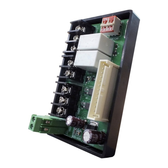
Page 7: Device Layout
1.4 Device Layout Refer to the following diagram for the product layout. 1.4.1 Wiring Connection Table Terminal Wiring Connection AHU W1 Connect to AHU W1 AHU W2 Connect to AHU W2 AHU R Connect to AHU R Flow switch Flow switch input terminal T/S W1 Connect to thermostat W1 T/S W2... -
Page 8: Installing The Device
WARNING Ensure that you have turned off the power to the water heater before installing the device. 2.1 Basic Principles The following diagram shows the basic operation of an NPE-180A/240A water heater system with the ComfortAir add-on controller. System Diagram... -
Page 9: Installing The Device In An Npe-180A/240A Water Heater
An outdoor sensor and a flow switch are supplied with the product. Use 18 AWG cables for thermostat wiring. Install NSF certified mixing valves and expansion tanks ONLY. 2.2 Installing the Device in an NPE-180A/240A Water Heater Follow the instructions to install the Navien ComfortAir in an NPE-180A/240A water heater. - Page 10 PCB from the tray but do NOT disconnect any cables or wires. Proceed directly to the next step. 5. Install the ComfortAir onto the NPE-180A/240A water heater’s PCB tray. Align the latch at the back of the case with the front lip of the PCB tray. Installing the Device...
- Page 11 6. Align the two latches at the back of the ComfortAir with the two catch bars at the back of the water heater’s PCB tray. Then pivot the ComfortAir onto the PCB tray until the latches snap-on to the catch bars. 7.
-
Page 12: Wiring The Device
3. Wiring the Device This section provides information required to plan and install the system wiring. 3.1 System Wiring Examples Refer to the following wiring diagrams to properly install wiring for various setups you may need in your system. Set DIP switch (SW) #3 as specified for each configuration. -
Page 13: 1-Stage Thermostat / 1-Stage Control Heating System
3.1.2 1-Stage Thermostat / 1-Stage Control Heating System Set DIP switch (SW) #3 to ‘Off’ to configure the system to use a 1-stage thermostat / 1-stage control. 3.1.3 2-Stage Thermostat / 2-Stage Control Heating System Set DIP switch (SW) #3 to ‘On’ to configure the system to use a 2-stage thermostat / 2-stage control. -
Page 14: Configuring The Cooling System (For A Heating / Cooling Combo System)
3.1.4 Configuring the Cooling System (for a Heating / Cooling Combo System) To configure the cooling system, connect the thermostat Y terminal to the AHU cooling input terminal Y , and connect the thermostat R terminal to the AHU R output. -
Page 15: Cable Connections
Follow the instructions below to connect the cables to the ComfortAir 3.2.1 Connecting the Outdoor Temperature Sensor Cable An outdoor temperature sensor is supplied with the Navien ComfortAir installation kit. Insert the exposed wire into the terminal. Then tighten the terminal screw with a screwdriver. -
Page 16: Connecting The Thermostat Cables
3.2.2 Connecting the Thermostat Cables The ComfortAir receives input signals from thermostats to control the AHU. Insert the fork connector into the contact. Then tighten the terminal screw with a screwdriver. Wiring the Device... -
Page 17: Connecting The Flow Switch Cables
3.2.3 Connecting the Flow Switch Cables Insert the fork connector into the contact. Then tighten the terminal screw with a screwdriver. Wiring the Device... -
Page 18: Connecting The Main Control Connector
Navien ComfortAir . Connect one end of the cable to the connector socket on the ComfortAir PCB. Then, connect the other end to the connector socket on the NPE-180A/240A water heater PCB. Wiring the Device... -
Page 19: Configuring The Device
4. Configuring the Device This section provides the information required to set the desired options for the NPE- 180A/240A water heater system with the ComfortAir add-on controller. 4.1 Pump Control Options CAUTION The drawings in this instruction are intended only as a guide and are not replacements for professional engineering drawings. - Page 20 A System with the Internal Circulation Pump Set the 2-way valve inside the water heater to ‘EXT’. For more information about settings, refer to “Selecting a Recirculation Mode (“A” model only)” in the Water Heater Installation Manual. WARNING An anti-scalding device must be installed in the system in order to limit the DHW output temperature and prevent scalding.
-
Page 21: Dhw Priority Options
4.2 DHW Priority Options Refer to the following options to configure the system’s DHW supply modes. 4.2.1 DHW Priority Mode When the system is configured for the DHW priority mode, space heating does not operate if there is DHW demand (the flow switch is ‘closed’). Set the DIP switch (SW) #2 to ‘Off’... -
Page 22: Configuring The Npe-180A/240A Water Heater
5. Configuring the NPE-180A/240A Water Heater This section provides information required to properly configure the NPE-180A/240A water heater to setup and utilize the functions provided by the ComfortAir add-on controller. 5.1 Entering the Service Information Mode Follow the instructions below to access the Service information mode. -
Page 23: Entering The R&D Information Menu
3. In the R&D information menu, use the Up (+) or Down (-) buttons to move to 2.PAR (Parameter information mode), and then press the Info button. Mode Display Technical Information Parameter Information 4. To return to the previous menu (R&D information menu), press the [Reset] button once. Configuring the NPE-180A/240A Water Heater... -
Page 24: Parameter Table
The following table lists the parameters used to configure the water heater system functions. No. Mode Display Pump Exercise Operation Time Burn Delay Time Pump Post Purge Time Outdoor Low Temperature Set-point Outdoor High Temperature Set-point CH MIN Set-point CH MAX Set-point 2-Stage T/S Output Heat-Capacity Configuring the NPE-180A/240A Water Heater... -
Page 25: Configuring Water Heater Functions
With this option activated, the NPE-180A/240A water heater monitors the pump operation. When it detects that a pump has not been used for a specific period, it runs the pump for a set duration. -
Page 26: Burn Delay Time (P.05)
To return to the <PARAMETER INFORMATION MENU MODE>, press the [Reset] button once. If no buttons are pressed for five minutes, the display will automatically return to the <PARAMETER INFORMATION MENU MODE>. Configuring the NPE-180A/240A Water Heater... -
Page 27: Pump Post Purge Time (P.06)
To return to the <PARAMETER INFORMATION MENU MODE>, press the [Reset] button once. If no buttons are pressed for five minutes, the display will automatically return to the <PARAMETER INFORMATION MENU MODE>. Configuring the NPE-180A/240A Water Heater... -
Page 28: Outdoor Reset Control (P07-P10)
‘740’ error message is displayed and the system operates the same way as with the Outdoor Reset OFF (DIP switch #1 ON) setting. Configuring the NPE-180A/240A Water Heater... - Page 29 To return to the <PARAMETER INFORMATION MENU MODE>, press the [Reset] button once. If no buttons are pressed for five minutes, the display will automatically return to the <PARAMETER INFORMATION MENU MODE>. Configuring the NPE-180A/240A Water Heater...
- Page 30 To return to the <PARAMETER INFORMATION MENU MODE>, press the [Reset] button once. If no buttons are pressed for five minutes, the display will automatically return to the <PARAMETER INFORMATION MENU MODE>. Configuring the NPE-180A/240A Water Heater...
- Page 31 To return to the <PARAMETER INFORMATION MENU MODE>, press the [Reset] button once. If no buttons are pressed for five minutes, the display will automatically return to the <PARAMETER INFORMATION MENU MODE>. Configuring the NPE-180A/240A Water Heater...
- Page 32 To return to the <PARAMETER INFORMATION MENU MODE>, press the [Reset] button once. If no buttons are pressed for five minutes, the display will automatically return to the <PARAMETER INFORMATION MENU MODE>. Configuring the NPE-180A/240A Water Heater...
- Page 33 To return to the <PARAMETER INFORMATION MENU MODE>, press the [Reset] button once. If no buttons are pressed for five minutes, the display will automatically return to the <PARAMETER INFORMATION MENU MODE>. Configuring the NPE-180A/240A Water Heater...
-
Page 34: Maintenance
6. Maintenance The Navien NPE-180A and NPE-240A water heaters that are used in the DHW/heating systems should be properly maintained and flushed on an annual basis. Please see the NPE Water Heater Service Manual for more details regarding annual servicing and maintenance. -
Page 35: Appendix
7. Appendix This section provides additional information to be considered when you design a hydronic system using an NPE-180A/240A water heater. 7.1 NPE-180A/240A Pressure Drop Curve 7.2 NPE-180A/240A Flow Rate Graph Appendix... -
Page 36: Npe-180A/240A Pump P-Q Curve
AHU in use. If the system uses an internal circulation pump with the NPE-180A/240A water heaters or pumps manufactured by SunTherm Corporation (MMVE0S4NAAA, MMVE0M4NAAA), the flow rate will be approximately 3 GPM. -
Page 37: Limited Warranty Navien, Inc
The date of original installation must be provided to Navien, and upon request, proof of the original installation date must also be provided to Navien. When the product is installed in a new construction, the commencement date shall be dated upon which the end-user takes title to the property. - Page 38 Warranty Exclusions Navien’s Limited Warranty shall be void in the event of an occurrence of any of the following: Improper installation, failure to install in strict compliance with the Installation Manual procedures, installed by a non-licensed installer, and installation in violation of applicable rules, laws or building codes.
- Page 39 If your ComfortAir requires service, you have several options for getting service: Contact Technical Support at 1-800-519-8794 or on the website: www.navien.com. For warranty service, always contact Technical Support first. Contact the technician or professional who installed your zone pump controller.