
Related Manuals for Samson 3787


Summary of Contents for Samson 3787
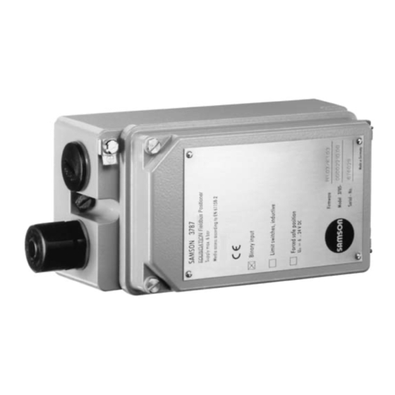
- Page 1 FOUNDATION FIELDBUS Positioner Type 3787 Fig. 1 ⋅ Type 3787 Mounting and Operating Instructions EB 8383-1 EN Firmware R 1.42/K 1.40 Edition November 2004...
-
Page 2: Table Of Contents
Contents Contents Page Design and principle of operation ..... . 8 Optional limit switches ......8 Communication . - Page 3 Contents Maintenance ....... 35 Servicing explosion-protected versions ....35 Parameter description .
- Page 4 Note: Devices with the CE mark meet the requirements specified in the Directive 94/9/EC and the Directive 89/336/EEC. The Declaration of Conformity can be viewed and downloaded from the SAMSON website at www.samson.de. Modifications of positioner firmware in comparison to previous versions Previous Positioner R 1.41...
- Page 5 Firmware modifications Communication K1.00 K1.20 Version compatible with user interface software version number: Fisher-Rosemount DeltaV in version 5.1 or higher National Instruments Fieldbus Configurator in version 2.3 or higher. All host systems certified by the Fieldbus Foundation Alteration to default values of the following parameters: AO Function Block CHANNEL, PID Function Block GAIN, PID Function Block RESET,...
- Page 6 Signal pressure (output) 0 bar up to the pressure of the supply air Characteristic, adjustable Globe valve: linear, equal percentage, reverse equal percentage, SAMSON butterfly valve: linear, equal percentage VETEC plug rotary valve: linear, equal percentage ≤1 % Deviation Dead band Adjustable from 0.1 to 10.0 % , default 0.5 %...
- Page 7 Stainless steel 1.4571 and 1.4301 Weight Approx 1.3 kg Versions of the positioner Model 3787 - Explosion protection Without II 2 G EEx ia IIC T6/ II 2 D IP 65 T 80 °C acc. to ATEX Ex ia FM/CSA II 3 G EEx ia IIC T6/ II 3 D IP 54 T 80 °C acc.
-
Page 8: Design And Principle Of Operation
It is suitable for attachment regardless of the output variable issued by to linear and rotary actuators. the microcontroller. The Type 3787 Positioner communicates as 1.1 Optional limit switches per FOUNDATION Fieldbus specification with field devices, programmable logic con- Limit switches can be retrofitted to the stand- trollers and process management systems. - Page 9 Design and principle of operation Configuration with NI-FBUS Configurator The NI-FBUS Configurator can be used to configure the whole FOUNDATION The positioner can also be configured using Fieldbus network. the NI-FBUS Configurator from National Instruments. An interface card installed in a PC is re- quired to connect it to FOUNDATION Fieldbus.
-
Page 10: Attachment To The Control Valve
2.1 Direct attachment to Type 3277 Actuator The positioner can be attached either di- rectly to a SAMSON Type 3277 Actuator The necessary accessories are listed in the or to control valves with cast yokes or rod- Tables 1, 2 and 3 on page 13. - Page 11 Attachment to the control valve Actuator stem retracts Actuator stem extends Internal signal pressure connection Signal pressure tube Connection block Venting Side view of connection block with seal (new) with switch plate (old) Symbol "actuator stem extends" Marking "Actuator stem retracts"...
- Page 12 Attachment to the control valve with the actuator symbol "actuator stem 8. Align the switchover plate with the extends" or "actuator stem retracts" to corresponding symbol for left attach- match the actuator version used. ment and screw the plate to the actua- If not, remove the three fastening tor yoke.
- Page 13 Attachment to the control valve Table 1 Actuator size Mounting kit Required lever with associated clamp and distance plate Order no. D1 (33 mm in length with clamp 17 mm in height) 120 (G 1/4) 1400-6790 120 (1/4 NPT) 1400-6791 D1 (33 mm in length with clamp 17 mm in height) 240 and 350 1400-6370...
-
Page 14: Attachment Acc. To Iec 60534-6
Attachment to the control valve 2.2 Attachment acc. to IEC 60534-6 2.2.1 Mounting sequence The positioner is attached according to Refer to Tables 4 and 5 on page 16 for re- NAMUR as shown in Fig. 4 using an adapt- quired mounting parts. - Page 15 Attachment to the control valve Mounting position Attachment to NAMUR rib 24 25 21 20 Attachment to rod Lever N1, N2 Plate Clamp Clamping plate Screw Pointer Shaft Lever of positioner Transmission pin Lock nut Bracket Studs Plate Nuts Mounting bracket Fig.
-
Page 16: Presetting The Valve Travel
Attachment to the control valve for the assigned travel, see Table 5. 2.2.2 Presetting the valve travel Intermediate values must be calculated. Move the clamp (21) beforehand to 1. Adjust the shaft (25) in the adapter clasp the pin. housing so that the black pointer (24) is aligned with the casted marking on the 5. -
Page 17: Attachment To Rotary Actuators
6. Relieve signal pressure from the actuator. mended for all angles of rotation larger than 90°). Table 6 Rotary actuators (Complete mounting parts, but without cam disks) SAMSON Type 3278 Actuator Attachmt. acc. to VDI/VDE 3845 Attachment to Masoneilan actuator Actuator Actuator Camflex I... -
Page 18: Mounting The Lever With Feeler Roll
2.3.4). tioner face the side of the diaphragm case. If the positioner is attached to a SAMSON Type 3278 Rotary Actuator, the air ex- Actuators according to VDI/VDE 3845 hausted from the positioner is admitted to the inside of the actuator without any addi- 1. - Page 19 Attachment to the control valve Attachment to SAMSON Type 3278 Attachment acc. to VDI/VDE 3845 Vent plug or filter check valve 33 Positioner 34 Intermediate piece 35 Lever with cam follower roll 36 Adapter 37 Transmission lever 38 Screws 39 Scale...
-
Page 20: Aligning And Mounting The Cam Disk
Attachment to the control valve 2. On aligning the cam disk, clip on the 2.3.3 Aligning and mounting the double-sided scale disk so that the scale cam disk matches the direction of rotation of the control valve. Only then secure the cam In rotary actuators with spring-return mech- disk with the fastening screws. - Page 21 Attachment to the control valve Feeler roll Starting point Holes to secure the cam disk Insert clip and then press tongues outwards View onto the actuator shaft from the positioner Control valve opens clockwise Control valve opens counterclockwise Fig. 6 ⋅ Aligning the cam disk EB 8383-1 EN...
-
Page 22: Reversing Amplifier For Double-Acting Actuators
Reversing amplifier for double-acting actuators Signal pressure connections 2.3.4 Reversing amplifier for double-acting actuators : Output A leading to the signal press- ure connection at the actuator which opens For the use with double-acting actuators, the valve when the pressure increases the positioner must be fitted with a revers- : Output A leading to the signal press-... - Page 23 Reversing amplifier for double-acting actuators From the positioner Output 38 Supply 9 To the actuator Reversing amplifier 1.1 Special screws 1.2 Gasket 1.3 Special nuts 1.4 Rubber seal 1.5 Plug 1.6 Filter 1.3 1.2 Fig. 7 ⋅ Mounting a reversing amplifier EB 8383-1 EN...
-
Page 24: Connections
Connections 3 Connections 3.1.1 Pressure gauge We recommend mounting pressure gauges 3.1 Pneumatic connections for supply air and signal pressure to moni- The air connections are either 1/4 NPT or tor the positioner. The parts are listed as ac- G 1/4 tapped holes. Customary fittings for cessories in Tables 3, 4 and 6. -
Page 25: Supply Air Pressure
Connections 3.1.2 Supply air pressure 3.2 Electrical connections The required supply air pressure depends For electrical installation, you are re- on the bench range and the operating direc- quired to observe the relevant elec- tion (fail-safe position) of the actuator. trotechnical regulations and the acci- The bench range is mentioned on the name- dent prevention regulations that... - Page 26 Connections To connect the bus line, loosen the coup- Caution! ling nut and the clamping insert from the The terminal assignment specified in positioner and remove the dust cap. the certificate must be adhered to. Slide the coupling nut and clamping in- Reversing the assignment of the elec- sert over the connecting cable.
- Page 27 Connections Limit switches Forced venting For operation of the limit switches, switch- For the positioners with forced venting func- ing amplifiers have to be connected in the tion, a voltage between 6 and 24 V DC output circuit. Their function is to control the must be connected to the terminals 81 and limit values of the control circuit according to NAMUR, thus ensuring operational relia-...
-
Page 28: Establishing Communication
EN 61158-2. Process management Supply unit system Termination FOUNDATION Fieldbus EN 61158-2 Termination FOUNDATION Fieldbus EN 61158-2 3787 3787 3787 3787 Process management Supply unit system FOUNDATION Fieldbus Ex-fieldbus barriers EN 61158-2... -
Page 29: Operation
Operation 4 Operation 4.1 LEDs There are two LEDs located inside the cover Warning! used to monitor the positioner during start- Before you take the control valve up, operation and to indicate possible faults. into operation, carefully move the General meaning of LEDs: control valve to its end position by covering the hole (manual oper- Device start-up or error,... -
Page 30: Write Protection And Simulation Switches
Operation 4.2 Write protection and simula- 4.4 Default setting tion switches All parameters are set to default values. See chapter 7 on description of parameters. There are two microswitches inside the hinged cover to activate the write protection and enable simulation. Note! Manual operation and activated final posi- When the write protection switch is ON, the... -
Page 31: Initialization
Dimensions Enter data on valve and actuator under 4.4.2 Initialization "Start-up" in the operating software. After connecting the supply air and electri- Set "Type of initialization" to "Rated cal connections to the bus cable, initializa- range", select "Maximum range" only tion must be started. - Page 32 Operation Final position at a reference variable A new initialization routine can only be larger than 125 % (function deactivated). started after this when the communication is connected. Fail-safe position "Actuator stem re- A completed initialization can be cancelled tracts": Direction of action: increasing/decreas- via the communication with the command ing (<>), the globe valve closes with in-...
-
Page 33: Operation Via Trovis-View
ATTACHMENT munication, the positioner can also be oper- Defines the attachment of the positioner ated with SAMSON’s TROVIS-VIEW user in- (Select: Namur/integrated). terface via the serial port integrated in the RATED_TRAVEL device. -
Page 34: Testing The Control Valve
Operation MAX_HUB 3. Set the Transducer Block to the "Auto" Maximum travel/angle of rotation in per- mode. cent of the rated travel/nominal angle. In the menu "Positioner-> Operating mode TRD" under "Required operating The integrated LEDs and the parameters mode" select "Automatic (AUTO)". SELF_CALIB_STATUS Deactivate the option "Local override SELF_CALIB_WARNUNG... -
Page 35: Maintenance
Maintenance Adjusting the switching point: 5 Maintenance The limit switches are marked GW1 and GW2 on the inside of the case cover. Yel- The positioner is maintenance-free. low tags and the associated adjustment Pneumatic connection 9/Supply contains a sieve with a mesh size of 100 µm. If re- screws (Fig. -
Page 36: Parameter Description
< 0201.ffo >, < 0201.sym > Capabilities File: < 020101.cff > You can order these Device Description files on disk (3 1/2") from SAMSON under the pro- duct number 1400-7705 or you can download them from the Internet at www.samson.de or www.fieldbus.org. -
Page 37: Legends Assigned To The Parameters
Parameter description 7.3.1 Legends assigned to the parameters = Read = Write Index = Relative index of the parameter in each block = Out of Service = Manual AUTO = Automatic = Cascade RCAS = Remote Cascade ROUT = Remote Output = Static parameter = Non-volatile parameter = Dynamic parameter... -
Page 38: Block Structure
Parameter description 7.4 Block structure FOUNDATION Fieldbus assigns all functions and data of a device to three different block types. Each block type has a different area of application. A FOUNDATION Fieldbus device has the following block types: One Resource Block The Resource Block contains all the hardware specific characteristics. - Page 39 Parameter description The SAMSON Type 3787 Foundation Fieldbus Positioner contains the following blocks: One Resource Block. One Standard Advanced Positioner Valve Transducer Block. Two Function Blocks: one Analog Output Function Block, one PID Function Block. Set point Set point PV, XD...
-
Page 40: Resource Block
Parameter description 7.4.1 Resource Block The Resource Block contains all the data that clearly identifies the device. It is, so to speak, the electronic nameplate of the device. The Resource Block’s parameters include, for example, device type, device name, manufac- turer ID, serial number as well as parameters which affect the behavior of all other Blocks in the device. - Page 41 Access: r Shows the device type in decimal number format. DEV_TYPE Index: 11 Access: r Display: 1 for Type 3787 DEVICE_ CERTIFICATION Type of protection, Index: 45 indicates whether Ex approvals for this field device are available. Access: r DEVICE_MESSAGE...
- Page 42 FREE_TIME Index: 25 function blocks. Access: r Note: This parameter is not supported as the function blocks of the Type 3787 are configured invariably. FREE_SPACE Shows the free memory (in percent) which is available to process additional function Index: 24 blocks.
- Page 43 Shows available configuration memory in kilobyte. Index: 22 Access: r Note: This parameter is not supported as the function blocks of the Type 3787 are configured as permanent. MIN_CYCLE_T Shows time duration of the shortest cycle interval of which the device is capable (execution time of the AO Function Block 50 ms).
- Page 44 Parameter description RS_STATE Shows the actual operating state of the Resource Block. Index: 7 Access: r Display: ONLINE Standard operation, the block is in the operating mode AUTO. STANDBY The Resource Block is in the operating mode O/S. ONLINE LINKING The configured links among the function blocks are still not set up.
- Page 45 Parameter description TEXT_INPUT_3 Freely available space for entering text. Index: 52 Access: r,w This alert is generated by any change to the static data, including date and time. UPDATE_EVT Index: 35 Access: r Shows status of the write protection alarm. WRITE_ALM Index: 40 Access: r, w...
-
Page 46: Transducer Block
1: active 0: inactive FINAL_VALUE_CUTOFF_HI Forced venting assembly Characteristic > _ MODE_BLOCK O/S selection Hardware, Firmware error CHARACT > _ in Type 3787 Supply air FINAL_VALUE_CUTOFF_LO > _ 1 & PD controller Fail-safe action Pneumatik SERVO_Gain_1 Block ACT_FAIL_ACTION SERVO_Gain_2 SERVO_RATE &... - Page 47 Parameter description Note: When initialization based on maximum range (default) is selected, the positioner can be started up directly after being attached to the control valve via the SELF_CALIB_CMD par- ameter. The results of the initialization are saved in SELF_CALIB_STATUS. When this type of initializa- tion is used, other parameters in this block generally do not require any adaptation.
- Page 48 Defines the attachment of the positioner to the control valve (with linear actuator). Index: 47 Access: r, w Input: INTEGRATED Attachment used with SAMSON Type 3277 Actuator. NAMUR Attachment acc. to DIN /IEC 534 (NAMUR). Default: INTEGRATED Note: Only the attachment acc. to VDI /VDE 3845 (NAMUR) is possible with rotary actuators.
- Page 49 VETEC ROTARY LINEAR VETEC ROTARY EQUAL PERCENTAGE Default: LINEAR COLLECTION_DIRECTORY Note: Index: 12 This parameter is not processed in the Type 3787. Access: r Dead band in percent of the rated travel /nominal angle. DEADBAND Index: 35 Access: r, w Range: 0.1 ...
- Page 50 Parameter description FINAL_VALUE_CUTOFF_LO Final position Index: 16 if the set point falls below the entered value, the valve is moved towards the final Access: r, w position that corresponds to 0 % of the manipulated variable. This is done by completely venting or filling the actuator (depending on the fail-safe position).
- Page 51 Parameter description MAX_HUB Maximum possible travel /angle of rotation Maximum travel/angle of rotation detected during initialization stated in percent of Index: 58 the rated travel/nominal angle. Access: r MODE_BLK Shows/used to select the actual operating mode of the Resource Block, permitted Index: 5 operating modes supported by the Transducer Block and the normal operating mode.
- Page 52 Parameter description SELF_CALIB_STATUS Status of sequence started with SELF_CALIB_CMD. Index: 56 Access: r Display: UNDETERMINED RUNNING ABORTED RANGE ERROR DEFECTIVE MECHANICS / PNEUMATICS TIMEOUT PROPORTIONAL RANGE RESTRICTED RATED TRAVEL OR TRANSMISSION ERROR MECHANICAL ERROR PNEUMATICAL ERROR INITIALIZATION STATUS: DETERMINATION OF MECHANICAL STOPS INITIALIZATION STATUS: DETERMINATION OF MINIMUM PULSES NITIALIZATION STATUS:...
- Page 53 Sum of the rated load cycles (double travels), sum of valve travels. Access: r TOT_VALVE_TRAV_LIM Total valve travel limit Index: 40 Access: r, w Range: 0...16 500 000 Default: 1 000 000 TRANSDUCER_DIRECTORY Note: Index: 9 This parameter is not processed in the Type 3787. Access: r EB 8383-1 EN...
- Page 54 Parameter description TRANSDUCER_STATE State of Transducer Block. Index: 32 Access: r Display: SEE ACTUAL MODE OF TRANSDUCER BLOCK FORCED VENTING ACTIVE LOWER TRAVEL LIMIT ACTIVE UPPER TRAVEL LIMIT ACTIVE END POSITION ACTIVE AT < END POSITION ACTIVE AT > Type of transducer, here "Standard Advanced Positioner Valve" TRANSDUCER_TYPE Index: 10 Access: r...
- Page 55 ROTARY (Control valve with a rotating plug, part-turn, rotary motion) OTHER Default: linear Note: Type 3787 differentiates merely between linear and rotary control valves. "Undefined" and "other" are treated as globe valves. XD_CAL_LOC Location of last calibration. Index: 29 Access: r, w Date of last calibration.
- Page 56 Parameter description XD_ERROR_EXT Extended error messages of the Transducer Block. Index: 33 Access: r Display: NONE (0) FAILURE MECHANICS FAILURE IN MEASUREMENT NOT INITIALIZED SELFCALIBRATION FAILED ZERO POINT ERROR INTERNAL CONTROL LOOP DISTURBED (Reset over SELF_CALIB_CMD -> RESET ‘CONTROL LOOP FAULT‘). TRAVEL TIME EXCEEDED (Automatic reset of control loop error message)
-
Page 57: Function Blocks
Parameter description 7.4.3 Function Blocks The Function Blocks contain the fundamental automation functions of the fieldbus device. There are various types of function blocks such as Analog Input Function Block , Analog Out- put Function Block and PID Block. Each of these function blocks is used to process various application functions (automation tasks) in the entire system. - Page 58 Parameter description (e.g. in %) XD_SCALE 100 % READBACK PV_SCALE 0 ˚C (e.g. in °C) SP_LO_LIM<=SP<=SP_HI_LIM Set point Set point PV, XD Output limits ramps scaling options SP_HI_LIM Sp_RATE_DN XD_SCALE IO_OPTS SP_LO_LIM Sp_RATE_UP PV_SCALE MODE_BLK MODE_BLK XD, PV scaling (manual) READBACK XD_SCALE, PV_SCALE Fig.
-
Page 59: Parameters Of The Analog Output Function Block
Note: CHANNEL must be set to a valid value before the AO Function Block can be put into operation. This value must be set to "1" as there is only one Transducer Block (Standard Advanced Positioner Valve) available in the Type 3787. FSTATE_TIME... - Page 60 Grant or limit the access of a fieldbus host system to the field device. Index: 13 Access: r, w Note: This parameter is not evaluated by the Type 3787. IO_OPTS Used to select the input/output block processing of the AO Block...
- Page 61 Parameter description MODE_BLK Shows the actual mode of the AO Block, the target modes, permitted modes supported Index: 5 by the AO Block and normal mode. Access: r, w Display: RCAS AUTO The AO Block supports the following modes: O/S (Out of Service) The AO algorithm of the block is not executed.
- Page 62 Parameter description RCAS_OUT Shows the analog reference variable (value and status) after ramping. Index: 28 This value is made available to the fieldbus host system to perform back calculations Access: r when the operating mode changes or with limited signals. Note: This parameter is only active in RCAS mode.
- Page 63 Parameter description SIMULATE Using the simulation the value and status of the process variable PV of the block can be Index: 10 simulated. Access: r, w Note: During simulation, the value of OUT is not passed onto the Transducer Block. The Transducer Block keeps the last valid value stored before the simulation was activated.
- Page 64 Parameter description STATUS_OPTS Used to select available status options to determine the treatment and processing of the Index: 15 status: Access: r, w in O/S Option: Uninitialized Propagate Fault Backward Status of the Transducer is passed on to the upstream connected Block using the status of BKCAL_OUT.
-
Page 65: Pid Function Block (Pid Controller)
Parameter description 7.4.3.2 PID Function Block (PID controller) A PID Function Block includes the input channel processing, the PID control and the analog output channel processing. The configuration of the PID Block (PID controller) is dependent on each automation task. Simple control loops, feedforward controls, cascade control and cascade control with limits can be implemented in combination with a further controller block. - Page 66 Parameter description nent RATE, the manipulated variable is calculated depending on the rate of change of the system deviation. An output value OUT is formed from the calculated manipulated variable corresponding to the OUT_SCALE, OUT_HI_LIM and OUT_LO_LIM parameters. This output value can be passed on to a downstream connected Function Block.
-
Page 67: Parameters Of The Pid Function Block
Parameter description Parameters of the PID Function Block ACK_OPTION This parameter allows you to choose whether an alarm should be automatically Index: 46 acknowledged in the device, i.e. without any influence from the fieldbus host system. Access: r, w Option: Undefined No option HI_HI_ALM... - Page 68 Parameter description ALERT_KEY The identification number of the plant unit. This information may be used in the Index: 4 fieldbus host system for sorting alarms and events. Access: r, w Input: 1...255 Default: Note: The value 0 (default) is not a tolerated value and is therefore rejected with an error message when writing to the device.
- Page 69 Parameter description BYPASS This parameter allows the calculation of the manipulated variable by means of the PID Index: 17 control algorithm to be switched on or off. Access: r, w in MAN, O/S Option: Unintialized Same as ON Bypass switched off: the manipulated variable determined by the PID control algorithm is issued over the OUT parameter.
- Page 70 Parameter description Reserved for block alarms. 3...7 The violation of the limit for the high deviation is issued with the corresponding priority (3= low priority, 7= high priority) to notify the user. 8...15 The violation of the limit for the high deviation is issued with the corresponding priority (8= low priority,15= high priority) as a critical alarm.
- Page 71 Grant or deny access of a fieldbus host system to the field device. GRANT_DENY Index: 12 Access: r, w Note: This parameter is not evaluated by the Type 3787. HI_ALM Shows the status of the alarm for the high alarm limit (HI_LIM), including details about Index: 61 the alarm timing (date, time) and the value which triggered the alarm.
- Page 72 Parameter description HI_PRI Determines the action to be taken when the high alarm limit (HI_LIM) is exceeded. Index: 50 Access: r, w The violation of the high alarm limit is not evaluated. Input: No message issued when a violation of the high alarm occurs. Reserved for block alarms.
- Page 73 Parameter description LO_LIM Input of the alarm limit for the low alarm (LO_ALM). Index: 53 If the PV value exceeds this limit, the LO_ALM alarm status parameter is issued. Access: r, w Input: Range and limit of the PV_SCALE Default: -3402823466 x 10 LO_PRI Determines the action to be taken when the value falls below the low alarm limit...
- Page 74 Parameter description Shows the manipulated variable, value, limit and status of the PID Function Block. Index: 9 Access: r, w in MAN, O/S Note: If the MAN mode in MODE_BLK is selected, the output value OUT can be entered manually here. The unit used is taken on by the OUT_SCALE parameter group.
- Page 75 Parameter description RESET Used to input the time constant for the integral function. Index: 24 Access: r, w Default: 3402823466 x 10 (maximum possible value) Note: The integral function is cleared by setting to 0 seconds. ROUT_IN Used to input and display the manipulated variable (value and status) provided by the Index: 33 fieldbus host system.
- Page 76 Parameter description Default: Uninitialized Note: This parameter is only active in the PID Block in the RCAS and ROUT modes. If it is set to "Uninitialized", the PID Block cannot be placed into RCAS or ROUT modes. Used to input the set point (reference variable) in AUTO mode. Index: 8 Access: r, w in AUTO, MAN, O/S...
- Page 77 Parameter description STATUS_OPTS Used to select available status options to determine the treatment and processing of the Index: 14 status: Access: r, w in O/S Option: Uninitialized IFS if Bad IN Fault state of the downstream connected AO Function Block initiated, if the controlled variable (IN) changes the status to BAD.
-
Page 78: Other Parameters
Parameter description 7.5 Other parameters 7.5.1 Stale counter The stale counter is used to assess the "quality" of a process variable received via a cyclically configured link (publisher subscriber link). The process variables that are "connected" among various function blocks are transferred using these links. -
Page 79: Diagnostic Messages
Diagnostic messages 8. Diagnostic messages 8.1 Messages of the XD_ERROR_EXT parameter (Transducer Block) Failure mechanics This message is issued when the entered rated travel is not reached on initialization. - Check mechanics and pneumatics in the valve - Compare the specifications in the Transducer Block, which describe the valve as well as the actuator and the mechanical structure, with the actual valve. -
Page 80: Messages Of The Xd_Error Parameter (Transducer Block)
Diagnostic messages Forced venting active Forced venting is activated, i.e. the signal at terminals +81 and -82 is smaller than 3V. The control valve moves to the fail-safe position irrespective of the control loop. It is auto- matically reset as soon as there is a 6V to 24 V DC signal at terminals +81 and -82. Device under Selftest This message is issued when the device is undergoing initialization or electric zero cali- bration. -
Page 81: Messages Of The Self_Calib_Status Parameter (Transducer Block)
Diagnostic messages - Check mechanics and pneumatics in the valve - Compare the specifications in the Transducer Block, which describe the valve as well as the actuator and the mechanical structure, with the actual valve. Reinitialize. Data Integrity Error Checksum error Algorithm Error Set point value - actual value error 8.3 Messages of the SELF_CALIB_STATUS parameter (Transducer Block) -
Page 82: Dimensional Drawing
Dimensional drawing Pneumatic connections G 1/4 or NPT 1/4 M20 x1.5 Direct attachment Output (38) 30.5 Supply (9) Attachment with intermediate piece for rotary actuators Attach. IEC 60534-6 with adapter housing Output 1 (A1) 28.5 Output 2 (A2) Supply (Z) Pneum. -
Page 83: Ec Type Examination Certificate
EB 8383-1 EN... - Page 84 EB 8383-1 EN...
- Page 85 EB 8383-1 EN...
- Page 86 EB 8383-1 EN...
- Page 87 EB 8383-1 EN...
- Page 88 EB 8383-1 EN...
- Page 89 EB 8383-1 EN...
-
Page 90: Csa/Fm Certification
EB 8383-1 EN... - Page 91 EB 8383-1 EN...
- Page 92 EB 8383-1 EN...
- Page 93 EB 8383-1 EN...
- Page 94 EB 8383-1 EN...
- Page 95 EB 8383-1 EN...
- Page 96 SAMSON AG ⋅ MESS- UND REGELTECHNIK Weismüllerstraße 3 ⋅ 60314 Frankfurt ⋅ Germany Phone: +49 69 4009-0 ⋅ Fax: +49 69 4009-1507 EB 8383-1 EN Internet: http://www.samson.de...