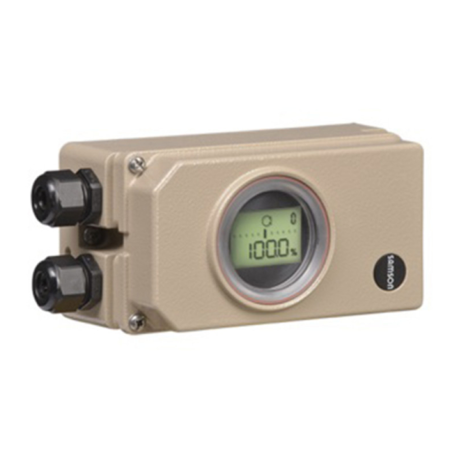
Samson 3730-4, 3730-5 - I/P Positioner Quick Guide
- Mounting and operating instructions (212 pages) ,
- Original instructions manual (128 pages) ,
- Configuration manual (100 pages)
Advertisement
This Quick Guide does not substitute the mounting and operating instructions delivered with the positioner. The warnings and safety instructions in the mounting and operating instructions must be followed.
Mounting
Direct attachment to SAMSON Type 3277 Actuator
| Travel [mm] | Actuator [cm²] | Lever | Pin position |
| 7.5 | 120 | M | 25 |
| 15 | 120, 175, 240, 350 | M | 35 |
| 30 | 355, 700, 750 | M | 50 |
→ To mount the positioner, lift the lever so that the follower pin rests on the follower clamp of the actuator stem. Make sure the lever can move freely.
NAMUR attachment
| Travel [mm] | Actuator [cm²] | Travel | Pin position |
| 7.5 | 60, 120 with Type 3510 Valve | S | 17 |
| 7.5 | 120 | M | 25 |
| 7.5 | 700, 750 | M | 35 |
| 15 | 120, 175, 240, 350 | M | 35 |
| 15, 30 | 355, 700, 750 | M | 50 |
| 30 | 1000, 1400, 2800 | L | 70 |
| 60 | 1000, 1400, 2800 | L | 100 |
| 120 | 1400, 2800 | XL | 200 |
| 200 | See manufacturer's specifications | XXL | 300 |
→ Determine the travel range of the control valve (closed position to as far it will go in the other direction) by applying the max. supply air to the actuator and then venting the actuator completely.
→ Fasten the lever with the follower pin onto the shaft of the positioner.
→ Fasten the NAMUR bracket onto the valve yoke so that it is aligned centrally to the slot of the follower plate when the travel position is at approx. 50%.
→ Fasten the positioner to the NAMUR bracket, making sure that the follower pin is in the slot of the follower plate. Make sure the lever can move freely.
Attachment to rotary actuators
| Lever | Pin position |
| M | 90° |
→ Place the valve into the closed position. Determine the opening direction.
→ Place the follower plate on the slotted actuator shaft and fasten it to the coupling wheel. Mount the top and bottom brackets to the actuator.
→ Fasten the positioner on the bracket. Make sure that:
- The lever with its follower pin engages the slot of the coupling wheel, while taking into account the opening direction.
- The lever in the middle valve position is parallel to the long side of the positioner housing.
Start‑up
- Apply supply air (1.4 to 7 bar).
- Connect electrical reference variable according to IEC 61158-2.
Set the fail‑safe position of the valve at the slide switch:
→ AIR TO OPEN (signal pressure opens the valve)
→ AIR TO CLOSE (signal pressure closes the valve)
Adapt the volume restriction Q (only <240 cm²):
MIN SIDE for connection at the side
MIN BACK for connection at the back
→ Initialize the positioner.
Configuration and operation
Each parameter has a code number which is shown in the display. Parameters that have a code marked with * can only be changed when they are enabled beforehand using Code 3 (display:  ).
).
- Select parameter/value: turn rotary pushbutton (
![]() )
) - Confirm parameter/value: press rotary pushbutton (
![]() )
) - Cancel action:
![]() until ESC then
until ESC then ![]()
 )
) )
)Initialization
Initialization mode: MAX (see EB for other modes)

Risk of crushing! During the initialization, the control valve moves through its entire travel range/angle of rotation.
Note: After changing the installation, reset the positioner before initialization (Code 36/Std).
→ Mount and start up the positioner, then press INIT key. READY! The positioner adapts itself automatically to the maximum travel/ rotational angle range of the control valve.
After applying the set point, the positioner goes to the last used operating mode. Code 0 appears on the display.
Codes/icons and their meaning
| Code | Meaning |
| 0 | Operating mode |
| 1 | Manual w |
| 2 | Reading direction |
| 3 | Enable configuration |
| 4* | Pin position |
| 5* | Nominal range |
| 6* | Initialization mode |
| 7* | Direction of action |
| 8*/9 | Travel/angle range start/end |
| 10/11* | Travel/angle upper/lower limit |
| 12/13* | w-start/end |
| 14/15* | Set point cutoff decrease/increase |
| 16* | Pressure limit |
| 17/18* | Kp/Tv step |
| 19* | Tolerance band |
| 20* | Characteristic |
| 21/22* | Required transit time OPEN/CLOSED |
| 23* | Total valve travel |
| 24* | LV total valve travel |
| 34* | Closing direction |
| 35* | Blocking position |
| 36* | Reset |
| 37* | Position transmitter option |
| 38* | Inductive alarm |
| 39-45 | Information (see EB) |
| 50-56 | Initialization errors (see EB) |
| 57-60 | Operational errors (see EB) |
| 62-67 | Hardware errors (see EB) |
| 68-78 | Data errors (see EB) |
| 79-81 | Diagnosis errors (see EB) |
Legend: w = set point; x = travel
| Icon | Meaning |
| Configuration enabled |
 | Maintenance demanded |
| S | Fail-safe position |
 blinks blinks | Not initialized |
 blinks blinks | Emergency mode |
| Err | Error |
| TunE | Autotuning |
| ZP | Zero calibration |
For detailed information on mounting and operation, refer to:
 EB 8384-4 for Type 3730-4, EB 8384-5 for Type 3730-5

Documents / ResourcesDownload manual
Here you can download full pdf version of manual, it may contain additional safety instructions, warranty information, FCC rules, etc.
Advertisement
Thank you! Your question has been received!


Need Assistance?
Do you have a question about the 3730-4 that isn't answered in the manual? Leave your question here.