Siemens ET 200pro Operating Instructions Manual
Small, extremely rugged and high-performance i/o system with ip65/66/67 degree of protection
Hide thumbs
Also See for ET 200pro:
- Operating instructions manual (270 pages) ,
- Quick manual (260 pages) ,
- Original instructions manual (256 pages)
Table of Contents
Advertisement
Quick Links
ET 200pro distributed I/O system
SIMATIC
ET 200pro distributed I/O system
Operating Instructions
03/2013
A5E00335544-08
___________________
Preface
___________________
Description
___________________
Application Planning
___________________
Mounting
___________________
Connection
___________________
Configuring
___________________
Commissioning
___________________
Maintenance and service
___________________
Functions
Alarm, error and system
___________________
messages
___________________
General technical data
___________________
Connection modules
___________________
Interface modules
___________________
Power modules
___________________
Digital electronic modules
___________________
Analog electronic modules
___________________
Pneumatic interface modules
___________________
Appendix
1
2
3
4
5
6
7
8
9
10
11
12
13
14
15
16
A
Advertisement
Table of Contents

Related Manuals for Siemens ET 200pro


Summary of Contents for Siemens ET 200pro
- Page 1 ___________________ ET 200pro distributed I/O system Preface ___________________ Description ___________________ Application Planning ___________________ Mounting SIMATIC ___________________ Connection ___________________ Configuring ET 200pro distributed I/O system ___________________ Commissioning ___________________ Maintenance and service Operating Instructions ___________________ Functions Alarm, error and system ___________________ messages...
- Page 2 Note the following: WARNING Siemens products may only be used for the applications described in the catalog and in the relevant technical documentation. If products and components from other manufacturers are used, these must be recommended or approved by Siemens. Proper transport, storage, installation, assembly, commissioning, operation and maintenance are required to ensure that the products operate safely and without any problems.
-
Page 3: Preface
This manual requires general knowledge of automation engineering. Scope of the manual This manual is valid for the specified components of the ET 200pro distributed I/O system. This manual contains a description of the components which were valid at the time the manual was published. - Page 4 Preface Position in the information landscape The table below provides an overview of the contents of the ET 200pro Distributed I/O System manuals. The manuals are available in the Internet (see Service & Support in the Internet). Manual Contents Operating instructions Mounting and connecting •...
-
Page 5: Operating Instructions, 03/2013, A5E00335544-08
Internet that contains this information. Special notes In addition to this manual, you also need the manual of your DP master / I/O Controller. ET 200pro distributed I/O system Operating Instructions, 03/2013, A5E00335544-08... - Page 6 The online catalog and online ordering system are available on the Internet (http://mall.automation.siemens.com). Training Center Siemens offers a variety of courses to help you get started with the ET 200pro and the SIMATIC S7 automation system. Please contact your regional Training Center, or the central Training Center in D-90327 Nuremberg.
- Page 7 Preface Note on IT security Siemens offers IT security mechanisms for its automation and drive product portfolio in order to support the safe operation of the plant/machine. We recommend that you inform yourself regularly on the IT security developments regarding your products. You can find information on this on the Internet (http://support.automation.siemens.com).
-
Page 8: Operating Instructions, 03/2013, A5E00335544
Preface ET 200pro distributed I/O system Operating Instructions, 03/2013, A5E00335544-08... -
Page 9: Table Of Contents
What is PROFIBUS DP? ......................18 What is PROFINET IO? ....................... 20 ET 200pro distributed I/O system ....................21 Components of the ET 200pro distributed IO system ..............23 Application Planning..........................29 Modular system ..........................29 Interface modules to suit your application ................... 32 Electronic modules to suit your application .................. - Page 10 Table of contents Connection ............................67 General rules and regulations for operating the ET 200pro ............67 Operation of the ET 200pro with Grounded Reference Potential ..........69 Electrical Configuration of ET 200pro ..................71 Technical specifications of the lines .................... 77 Connecting the interface module to a CM IM DP Direct connection module ......
- Page 11 Table of contents Commissioning ........................... 153 PROFIBUS DP ........................... 153 6.1.1 Commissioning ET 200pro ......................153 6.1.2 Startup of ET 200pro ........................154 PROFINET IO ..........................155 6.2.1 Commissioning ET 200pro ......................155 6.2.2 Startup of ET 200pro ........................156 Maintenance and service ........................
- Page 12 Interruption of the ET 200pro backplane bus ................227 9.2.5.5 Incorrect module combination ....................228 9.2.5.6 Diagnostics of faulty configuration states of ET 200pro on PROFINET IO ......228 9.2.5.7 Failure of the load voltage from the power module ..............228 9.2.5.8 STOP of the IO controller and recovery of the IO device ............
- Page 13 Digital electronic module 4 DIO / 4 DO DC 24V/0.5A (6ES7143-4BF00-0AA0) ....... 369 14.9 Overview of parameters of the digital electronic modules ............375 14.10 Overview of parameters of the digital electronic modules ............379 ET 200pro distributed I/O system Operating Instructions, 03/2013, A5E00335544-08...
- Page 14 Analog output module ....................... 504 A.3.6 Pneumatic interface module...................... 505 Response times ........................506 A.4.1 Response times between the DP master and ET 200pro ............506 A.4.2 DP master response times ......................506 ET 200pro distributed I/O system Operating Instructions, 03/2013, A5E00335544-08...
- Page 15 A.5.6 Connecting thermocouples to analog inputs ................520 A.5.7 Connecting actuators to the analog inputs ................523 Fail-safe shutdown of the ET 200pro Standard edition modules ..........524 Glossary ............................. 527 Index..............................537 ET 200pro distributed I/O system Operating Instructions, 03/2013, A5E00335544-08...
- Page 16 Table of contents ET 200pro distributed I/O system Operating Instructions, 03/2013, A5E00335544-08...
-
Page 17: Description
● the high-performance PROFIBUS DP and its high data transmission rates provide a smooth flow of communication between the CPU and the distributed I/O systems ● PROFINET IO ET 200pro distributed I/O system Operating Instructions, 03/2013, A5E00335544-08... -
Page 18: What Is Profibus Dp
CPU via PROFIBUS DP. Which devices can be connected to PROFIBUS DP? PROFIBUS DP supports all DP masters or DP slaves which are compatible with the IEC 61784-1: 2010 Ed3 CP 3/1 standard. ET 200pro distributed I/O system Operating Instructions, 03/2013, A5E00335544-08... - Page 19 PROFIBUS DP interface. DP slaves are the distributed I/O systems which are connected to the DP masters via PROFIBUS DP. Figure 1-1 Typical configuration of a PROFIBUS DP network ET 200pro distributed I/O system Operating Instructions, 03/2013, A5E00335544-08...
-
Page 20: What Is Profinet Io
Structure of a PROFINET IO network The figure below illustrates the typical layout of a PROFINET IO network. Existing PROFIBUS slaves can be integrated by an IE/PB link. Figure 1-2 Structure of a PROFINET IO network ET 200pro distributed I/O system Operating Instructions, 03/2013, A5E00335544-08... -
Page 21: Et 200Pro Distributed I/O System
IP67. Fields of application A robust design and degree of protection IP65, IP66, or IP67 make the ET 200pro distributed I/O system particularly suitable for use in rugged industrial environments. With IP65, IP66 and IP67, the ET 200pro is protected against the ingress of foreign bodies and water. - Page 22 Description 1.4 ET 200pro distributed I/O system Example configuration The figure below shows an example configuration of the ET 200pro. ① CM IM DP Direct connection module for the interface module ② Connection modules for electronic modules ③ Terminating module ④...
-
Page 23: Components Of The Et 200Pro Distributed Io System
1.5 Components of the ET 200pro distributed IO system Components of the ET 200pro distributed IO system Components of the ET 200pro distributed I/O system The table below lists the most important components of ET 200pro (Page 478). Table 1- 1 Components of ET 200pro... - Page 24 Description 1.5 Components of the ET 200pro distributed IO system Component Function View Connection The connection modules are mounted modules for on the interface modules. They are interface used to connect PROFIBUS DP, the modules with electronics/encoder supply and the PROFIBUS DP load voltage supply.
- Page 25 Description 1.5 Components of the ET 200pro distributed IO system Component Function View Connection The connection modules are mounted modules for the on the interface module. They are interface used to connect PROFINET IO and module the electronic, encoder, and load (6ES7154- voltage supplies.
- Page 26 Description 1.5 Components of the ET 200pro distributed IO system Component Function View Connection The connection modules are mounted modules for on the power modules. They are used PM-E power to connect the 2L+ load voltage modules supply. The following connection modules are...
- Page 27 Description 1.5 Components of the ET 200pro distributed IO system Component Function View Electronic The electronic module determines the module with function of the input and output bus module channels. The unit is supplied with the electronic module mounted on the bus module.
- Page 28 Description 1.5 Components of the ET 200pro distributed IO system Component Function View Connection The connection modules are mounted modules for on the electronic modules. They are electronic used to connect sensors and modules actuators. The following connection modules are...
-
Page 29: Application Planning
Application Planning Modular system Modular system A modular system in the context of ET 200pro means: With the extensive ET 200pro product range, you can adapt the configuration to your applications. ET 200pro distributed I/O system Operating Instructions, 03/2013, A5E00335544-08... - Page 30 2.1 Modular system Example: ET 200pro with electronic modules The ET 200pro can be equipped up to the maximum configuration with electronic modules. Between an interface module and a terminating module you can adapt the electronic modules to your application in whatever configuration you require.
- Page 31 Between an interface module and a terminating module you can adapt the electronic modules, motor starters and frequency converters to your applications in whatever configuration you require. The figure below shows an example configuration of the ET 200pro distributed I/O system with motor starter and repair switch module. ①...
-
Page 32: Interface Modules To Suit Your Application
IM 154-2 DP High Feature DPV0 slave DPV1 slave Application of ET 200pro fail-safe modules IO devices for PROFINET IO IM 154-4 PN High Feature IO device Application of ET 200pro fail-safe modules ET 200pro distributed I/O system Operating Instructions, 03/2013, A5E00335544-08... -
Page 33: Electronic Modules To Suit Your Application
4 AI RTD High Feature 4 input channels Measuring temperatures with Resistance measurement: resistance thermometers 150 Ω; 300 Ω; 600 Ω; 3000 Ω Resistance thermometer: Pt100; Ni100; Ni120; Pt200; Ni200; Pt500; Ni500; Pt1000; Ni1000 ET 200pro distributed I/O system Operating Instructions, 03/2013, A5E00335544-08... - Page 34 FESTO valve terminal CPV14 Nominal flow rate air 800 l/min Controlling RFID See RFID systems (http://support.automation.siemens.com/WW/view/en/32622825) , RF170C operating instructions. Controlling motor starters See ET 200pro Motor Starter (http://support.automation.siemens.com/WW/view/en/22332388) operating instructions. Controlling frequency converters See SIMATIC ET 200pro FC (http://support.automation.siemens.com/WW/view/en/28561828) operating instructions.
-
Page 35: Connection Modules To Suit Your Application
(1L+/2L+) Connecting and forwarding PROFINET IO using push-pull cable CM IM PN PP FO connectors (SC RJ), fiber optic cables Connecting and forwarding the supply voltages using push-pull cable connectors (1L+/2L+) ET 200pro distributed I/O system Operating Instructions, 03/2013, A5E00335544-08... - Page 36 The chapter "Options for combining modules" includes an overview in the table Electronic modules in combination with connection modules (Page 38) to show you which connection module can be combined with which electronic module. See also Options for Combining Modules (Page 37) ET 200pro distributed I/O system Operating Instructions, 03/2013, A5E00335544-08...
-
Page 37: Options For Combining Modules
7/8" IM 154-1 DP • • • IM 154-2 DP High • • • Feature IM 154-4 PN High • • • Feature 6ES7154-4AB10- 0AB0 IM 154-4-8 CPU • 6ES7154-8AB00- 0AB0 ET 200pro distributed I/O system Operating Instructions, 03/2013, A5E00335544-08... - Page 38 • 4 AI I High Feature • 4 AI RTD High Feature • 4 AI TC High Feature • 4 AO U High Feature • 4 AO I High Feature • ET 200pro distributed I/O system Operating Instructions, 03/2013, A5E00335544-08...
-
Page 39: Placing Power Modules
Placement of PM-E power module Power modules In the ET 200pro distributed I/O system, you can place the power modules at any location to the right of the interface module. The first power module is already integrated in the interface module. -
Page 40: Placement Of Pm-O Dc 2X24V Outgoing Module
The 1L+ electronic/encoder supply of the outgoing module is protected by means of an electronic circuit and is short-circuit proof. The 2L+ load voltage supply is protected by means of the PM-E power module or the interface module of the ET 200pro distributed I/O system. -
Page 41: Maximum Configuration
Application Planning 2.7 Maximum configuration Maximum configuration Mechanical maximum configuration The maximum configuration of an ET 200pro is reached when one of the rules outlined below applies: Table 2- 9 Mechanical maximum configuration Properties Rule Number of modules max. 16 electronic modules Width of ET 200pro max. - Page 42 Application Planning 2.8 TIA Selection Tool ET 200pro distributed I/O system Operating Instructions, 03/2013, A5E00335544-08...
-
Page 43: Mounting
Mounting Requirements Preassembling ET 200pro modules The ET 200pro modules can be preassembled on a narrow or wide rack version before installing the rack on site. Mounting position An ET 200pro can be mounted in any position. Note If you configure the ET 200pro Distributed I/O System with the ET 200pro FC frequency converter, observe the restrictions regarding the mounting position. -
Page 44: Rack
• motor starters, and frequency converters Vibration resistance In order to achieve the guaranteed vibration resistance of all ET 200pro modules, always use all mounting holes to mount the rack. Rack with a length of 2000 mm Cut the 2000 mm rack to suit your requirements, and drill mounting holes for the M8 screws. - Page 45 Always make sure you have a low-impedance connection between the rack and ground potential. If you do not install the rack on a grounded surface, always create a low-impedance connection to ground potential, for example, with the help of a copper braid. ET 200pro distributed I/O system Operating Instructions, 03/2013, A5E00335544-08...
-
Page 46: Mounting Wide And Narrow Racks
Mounting 3.2 Rack 3.2.2 Mounting wide and narrow racks Introduction The ET 200pro is preassembled on a narrow or wide rack. Dimensions for the narrow rack Figure 3-1 Dimension drawing for narrow rack ET 200pro distributed I/O system Operating Instructions, 03/2013, A5E00335544-08... - Page 47 Mounting 3.2 Rack Dimensions for the wide rack Figure 3-2 Dimension drawing for the wide rack ET 200pro distributed I/O system Operating Instructions, 03/2013, A5E00335544-08...
- Page 48 5. Connect the opposite end of the grounding cable to ground potential. Note Ensure adequate equipotential bonding. Figure 3-3 Grounding a narrow rack ET 200pro distributed I/O system Operating Instructions, 03/2013, A5E00335544-08...
-
Page 49: Mounting Compact Type Racks
Mounting 3.2 Rack 3.2.3 Mounting Compact Type Racks Introduction Mount the compact type rack onto the carrier before you mount your ET 200pro. ET 200pro distributed I/O system Operating Instructions, 03/2013, A5E00335544-08... - Page 50 Mounting 3.2 Rack Dimensions of the compact-narrow rack The dimensional drawing below shows the mounting hole dimensions of the compact-narrow type rack. Figure 3-4 Dimension drawing of compact-narrow rack ET 200pro distributed I/O system Operating Instructions, 03/2013, A5E00335544-08...
- Page 51 Mounting 3.2 Rack Dimensions of the compact-wide rack The dimension drawing below shows the mounting hole dimensions of the compact-wide type rack. Figure 3-5 Dimension drawing of compact-wide rack ET 200pro distributed I/O system Operating Instructions, 03/2013, A5E00335544-08...
- Page 52 6. Connect the opposite end of the grounding cable to ground potential. Note Ensure adequate equipotential bonding. ET 200pro distributed I/O system Operating Instructions, 03/2013, A5E00335544-08...
-
Page 53: Mounting The Interface Module
Mounting 3.3 Mounting the Interface Module Mounting the Interface Module Introduction The interface module interconnects ET 200pro with PROFIBUS DP/ PROFINET IO and supplies power to the electronic modules. Requirements ● Interface modules for PROFIBUS DP – The terminating module is removed from the interface module. - Page 54 See also Connecting the Interface Module to a CM IM DP ECOFAST Cu Connection Module (Page 87) Connecting the Interface Module to the CM IM DP M12, 7/8" Connection Module (Page 91) ET 200pro distributed I/O system Operating Instructions, 03/2013, A5E00335544-08...
-
Page 55: Mounting The Power Module
You connect the 2L+ load voltage supply to the power module. The power module opens a new load group (sourcing) for the electronic modules of ET 200pro. The power module and the corresponding bus module are supplied in gray color in order to prevent mistakes. -
Page 56: Mounting The Electronic Module
● The interface module is inserted into the relevant bus module (as delivered). ● The connection module may not be installed when you move the electronic module to a position further on the left side. ET 200pro distributed I/O system Operating Instructions, 03/2013, A5E00335544-08... - Page 57 • You will need to apply some more pressure in order to engage the module with the interface module or previous electronic module and to achieve appropriate seal tightness. Figure 3-7 Mounting electronic modules See also Replacing a bus module (Page 164) ET 200pro distributed I/O system Operating Instructions, 03/2013, A5E00335544-08...
-
Page 58: Installing The Pneumatic Interface Module
FESTO valve terminal with sponge-rubber seal (on the bottom) ② Connection plate ③ Pneumatic interface module ④ Bus module ⑤ Position of the O-rings for sealing Figure 3-8 Installing the pneumatic interface module ET 200pro distributed I/O system Operating Instructions, 03/2013, A5E00335544-08... - Page 59 ● In the as-delivered state there is a screw on the FESTO valve terminal for attaching the functional earth. This screw is not needed when the FESTO valve terminal is used in the ET 200pro and must be removed prior to mounting. Note...
- Page 60 The pneumatic interface module may not become skewed when you move it. An increased force has to be exercised to get the module to snap into the previous module and achieve a tight seal. ET 200pro distributed I/O system Operating Instructions, 03/2013, A5E00335544-08...
- Page 61 There are two O-rings mounted on the connection plate; these seal the space between the connection plate the electronic module. If you replace the pneumatic interface module you must also replace the two O-rings size 5x1.2. ET 200pro distributed I/O system Operating Instructions, 03/2013, A5E00335544-08...
-
Page 62: Mounting The Terminating Module
3.7 Mounting the terminating module Mounting the terminating module Introduction The ET 200pro is terminated using a terminating module. The terminating module must be mounted to enable operation of the ET 200pro. Requirements ● You have mounted all electronic modules of ET 200pro. -
Page 63: Replacing Labeling And Module Identification Labels
1. Push the screwdriver into the small opening of the label, and then lever it out. 2. Use your finger to press the new label into the holder of the module. ① Module label ② Labels Figure 3-12 Replacing labels ET 200pro distributed I/O system Operating Instructions, 03/2013, A5E00335544-08... -
Page 64: Setting The Profibus Dp Address And Terminating Resistor
Set the PROFIBUS DP address and terminating resistor at the connection module for the interface module. ● The PROFIBUS address defines the point of access to the ET 200pro on PROFIBUS DP. ● A PROFIBUS DP segment must be terminated at both ends, in other words on the first and last segment node, with its characteristic impedance. - Page 65 1. Remove the cap from the connection module. 2. Set the PROFIBUS DP address using the DIP switches (see the example below). 3. If this ET 200pro is the last node on PROFIBUS DP, enable the terminating resistor using the DIP switch.
- Page 66 Mounting 3.9 Setting the PROFIBUS DP Address and Terminating Resistor ET 200pro distributed I/O system Operating Instructions, 03/2013, A5E00335544-08...
-
Page 67: Connection
General rules and regulations for operating the ET 200pro Introduction When operating the ET 200pro distributed I/O system as part of a plant or system, special rules and regulations have to be followed depending on the field of application. This chapter provides an overview of the most important rules you must observe when integrating the ET 200pro distributed I/O system into a plant or system. - Page 68 Connection 4.1 General rules and regulations for operating the ET 200pro 24 V DC power supply The following table identifies requirements you must observe for the 24 V DC supply. With ... you must ensure ... buildings external lightning Install lightning protection protection (e.g.
-
Page 69: Operation Of The Et 200Pro With Grounded Reference Potential
Safe electrical isolation (SELV/PELV to IEC 60364-4-41) ET 200pro may only be operated on power supplies / power supply modules with safe electrical isolation. Configuring ET 200pro with grounded reference potential In an ET 200pro configuration with grounded reference potential, any interference current is discharged to protective ground. - Page 70 ① Disconnecting device for control system, signal transmitters and final controlling elements ② Short-circuit and overload protection ③ The connection between 1M and FE is not applicable in an ET 200pro configuration with ungrounded reference potential. ④ Ground busbar ⑤...
-
Page 71: Electrical Configuration Of Et 200Pro
ET 200pro configuration with CM IM DP Direct connection module The figure below shows the electrical potentials of an ET 200pro configuration with the CM IM DP Direct connection module on the IM 154-1 DP or IM 154-2 DP High Feature interface module. - Page 72 ET 200pro configuration with CM IM DP ECOFAST Cu connection module The figure below shows the electrical potentials of an ET 200pro configuration with the CM IM DP ECOFAST Cu connection module on the IM 154-1 DP or IM 154-2 DP High Feature interface module.
- Page 73 ET 200pro configuration with CM IM DP M12, 7/8" connection module The figure below shows the electrical potentials of an ET 200pro configuration with the CM IM DP M12, 7/8" connection module on the IM 154-1 DP or IM 154-2 DP High Feature interface module.
- Page 74 ET 200pro configuration with CM IM PN M12, 7/8" connection module The figure below shows the electrical potentials of an ET 200pro configuration with a CM IM PN M12, 7/8" connection module on the IM154-4 PN High Feature interface module (6ES7154-4AB10-0AB0).
- Page 75 ET 200pro configuration with CM IM PN PP Cu connection module The figure below shows the electrical potentials of an ET 200pro configuration with a CM IM PN PP Cu connection module on the IM154-4 PN High Feature interface module (6ES7154-4AB10-0AB0).
- Page 76 ET 200pro configuration with CM IM PN PP FO connection module The figure below shows the electrical potentials of an ET 200pro configuration with a CM IM PN PP FO connection module on the IM154-4 PN High Feature interface module (6ES7154-4AB10-0AB0).
-
Page 77: Technical Specifications Of The Lines
Connection 4.4 Technical specifications of the lines Equipment fusing Replaceable fuses for protecting the ET 200pro: ● Interface module: The bus module of the interface module is equipped with fuses for the electronic/encoder supply 1L+ and load voltage supply 2L+ (glass tube fuse; 5x20; type 194; 12.5 A; fast- blow), and a replacement fuse. -
Page 78: Connecting The Interface Module To A Cm Im Dp Direct Connection Module
DIP switch for setting the PROFIBUS DP address Requirements ● The interface module and bus module are mounted on the rack. ● You have set the PROFIBUS DP address on the connection module according to your configuration. ET 200pro distributed I/O system Operating Instructions, 03/2013, A5E00335544-08... - Page 79 Cable/PROFIBUS ECOFAST Hybrid Cable GP PROFIBUS cable 4-wire cable PROFIBUS cable 4-wire cable PROFIBUS cable 4-wire cable PB Hybrid Standard 2-wire cable Cable/PB Hybrid Robust Cable PROFIBUS cable 2-wire cable PROFIBUS cable 2-wire cable ET 200pro distributed I/O system Operating Instructions, 03/2013, A5E00335544-08...
-
Page 80: Preparing Profibus Dp Cables
1. Strip the PROFIBUS DP cable as shown in the figure. Figure 4-7 Stripping dimensions for the PROFIBUS DP cable Result You can now connect the power supply and PROFIBUS DP cables. ET 200pro distributed I/O system Operating Instructions, 03/2013, A5E00335544-08... -
Page 81: Preparing Profibus Hybrid Cables For The Connection At Cm Im Dp Direct
● PROFIBUS ECOFAST Hybrid Cable, 6-wire ● PROFIBUS ECOFAST Hybrid Cable GP, 6-wire, suitable for cable carriers ① Conductor for supply voltage ② Filler ③ Conductor for PROFIBUS DP ④ Shielding braid ⑤ Shielding film ET 200pro distributed I/O system Operating Instructions, 03/2013, A5E00335544-08... - Page 82 3. Slide the shielding braid back towards the sheath by approx. 15 +/-2 4. Carefully strip off the shielding film and the two white fillers from the PROFIBUS DP cable. Figure 4-8 Stripping dimensions for PROFIBUS Hybrid cables ET 200pro distributed I/O system Operating Instructions, 03/2013, A5E00335544-08...
- Page 83 PROFIBUS Hybrid cable with heat-shrink tubing Result You can now connect the power supply and PROFIBUS DP cables. See also Connecting PROFIBUS DP (Page 84) Connecting the supply voltages (Page 85) ET 200pro distributed I/O system Operating Instructions, 03/2013, A5E00335544-08...
-
Page 84: Connecting Profibus Dp
This may pose a problem the next time you connect a wire. You should thus always ensure not to leave any insulation residue in the insulation displacement terminal when you open it and remove the wire. ET 200pro distributed I/O system Operating Instructions, 03/2013, A5E00335544-08... -
Page 85: Connecting The Supply Voltages
X01, and the daisy-chaining cables on terminal X02 (electronic / encoder supply 1L+, load voltage supply 2L+). Figure 4-11 Connecting the supply voltage See also Terminating and installing the connection module (Page 86) ET 200pro distributed I/O system Operating Instructions, 03/2013, A5E00335544-08... -
Page 86: Terminating And Installing The Connection Module
5. Screw down the connection module to the interface module (torque = 1.5 N/m). Tighten the four screws evenly, working in cross-wise passes. The screws are already inserted in the connection module. ET 200pro distributed I/O system Operating Instructions, 03/2013, A5E00335544-08... -
Page 87: Connecting The Interface Module To A Cm Im Dp Ecofast Cu Connection Module
● If you are fabricating your own cables: – PROFIBUS ECOFAST hybrid cable, unassembled – PROFIBUS ECOFAST Hybrid Plug 180 (ECOFAST Cu) with Hanbrid connector – PROFIBUS ECOFAST Hybrid Plug, angled, (ECOFAST Cu) with Hanbrid connector ET 200pro distributed I/O system Operating Instructions, 03/2013, A5E00335544-08... - Page 88 Ground for electronics/encoder supply 1M Ground for load voltage supply 2M 2L+ load voltage supply Note The cable shield support is described in the Hardware Installation Instructions for the ECOFAST cable connector. ET 200pro distributed I/O system Operating Instructions, 03/2013, A5E00335544-08...
- Page 89 Observe the mechanical coding of the cable connectors for feeding and forwarding. 5. Push up the interlock mechanism of the ECOFAST cable connectors. Figure 4-12 Connecting the ECOFAST cable connectors ET 200pro distributed I/O system Operating Instructions, 03/2013, A5E00335544-08...
- Page 90 NOTICE Removing the ECOFAST cable connector It is not permissible to remove the ECOFAST cable connector while ET 200pro is in operation! Always switch off the 1L+ electronics/encoder supply and the 2L+ load voltage supply before you remove the ECOFAST cable connector.
-
Page 91: Connecting The Interface Module To The Cm Im Dp M12, 7/8" Connection Module
● The terminating resistor must be activated if no loop cables are connected. Required tools Screwdriver and stripping tool for wiring the M12 and 7/8" cable connectors, if you are fabricating your own cables. ET 200pro distributed I/O system Operating Instructions, 03/2013, A5E00335544-08... - Page 92 1L+ electronics/encoder supply 2L+ load voltage supply 7/8" cable connector for looping X02 Ground for load voltage supply Ground for electronics/ encoder supply 1M Functional earth 1L+ electronics/encoder supply 2L+ load voltage supply ET 200pro distributed I/O system Operating Instructions, 03/2013, A5E00335544-08...
- Page 93 ** We recommend that you connect the functional earth via the M12 thread (because it has a larger surface area than terminal 5). Note The cable shield support is described in the Hardware Installation Instructions for the M12 cable connector. ET 200pro distributed I/O system Operating Instructions, 03/2013, A5E00335544-08...
- Page 94 NOTICE Removing the 7/8" cable connector It is not permissible to remove the 7/8" cable connectors while ET 200pro is in operation! Always switch off the 1L+ electronics/encoder supply and the 2L+ load voltage supply before you pull or plug the 7/8" cable connector.
-
Page 95: Connecting The Im 154-4 Pn High Feature Interface Module With Cm Im Pn M12, 7/8
The IM 154-4 High Feature interface module is equipped with an internal PROFINET switch. This allows the direct forwarding of PROFINET or the direct connection of an additional IO device (e.g., ET 200pro with IM 154-8 CPU). X02 P1 R... - Page 96 ● Preassembled cables with M12 and 7/8" cable connectors. The cables are available in different lengths. ● If you are fabricating your own cables: – M12: 4-core, shielded bus cable, and d-coded M12 cable connector (PROFINET) – 7/8": 5-core cable and 7/8" cable connector ET 200pro distributed I/O system Operating Instructions, 03/2013, A5E00335544-08...
- Page 97 Ground for electronics/encoder supply 1M Functional earth 1L+ electronics/encoder supply 2L+ load voltage supply Note The cable shield support is described in the Hardware Installation Instructions for the M12 cable connector. ET 200pro distributed I/O system Operating Instructions, 03/2013, A5E00335544-08...
- Page 98 NOTICE Removing the 7/8" cable connector It is not permissible to remove the 7/8" cable connectors while ET 200pro is in operation! Always switch off the 1L+ electronics/encoder supply and the 2L+ load voltage supply before you pull or plug the 7/8" cable connector.
-
Page 99: Connecting The Im 154-4 Pn High Feature Interface Module With Cm Im Pn Pp Cu
The IM 154-4 High Feature interface module is equipped with an internal PROFINET switch. This allows the direct forwarding of PROFINET or the direct connection of an additional IO device (e.g., ET 200pro with IM 154-8 CPU). X03 DC 24V... - Page 100 – 5-wire cable and push-pull cable connector for 1L+/2L+ – 4-core, shielded cable (bus cable) and push-pull cable connector for RJ45 Note Refer to the manufacturer's documentation if you are fabricating the cables with the push-pull cable connectors. ET 200pro distributed I/O system Operating Instructions, 03/2013, A5E00335544-08...
- Page 101 Ground GND Receive Data- Transmit Data- RD_N TD_N Ground GND Ground GND Note The cable shield support is described in the Hardware Installation Instructions for the push- pull cable connector (PROFINET). ET 200pro distributed I/O system Operating Instructions, 03/2013, A5E00335544-08...
- Page 102 NOTICE Removing the push-pull cable connectors It is not permissible to remove the push-pull cable connector for 1L+/2L+ while ET 200pro is in operation! Always switch off the 1L+ electronics/encoder supply and the 2L+ load voltage supply before you pull or plug the push-pull cable connector.
-
Page 103: 4.10 Connecting The Im 154-4 Pn High Feature Interface Module With Cm Im Pn Pp Fo
CM IM PN PP FO connection module have been installed on the rack. Required tools ● Screwdriver ● Stripping tool for wiring the push-pull cable connector, if you are fabricating your own cables. ET 200pro distributed I/O system Operating Instructions, 03/2013, A5E00335544-08... - Page 104 If you are reusing fiber-optic cable, you must shorten both fiber-optic cores by the amount of the curved lengths and reinstall the cable connectors. This will prevent any attenuation losses caused by re-bent, heavily-stressed portions of the fiber-optic cores. ET 200pro distributed I/O system Operating Instructions, 03/2013, A5E00335544-08...
- Page 105 Ground for load voltage supply 2M Functional earth Push-pull cable connector (SC RJ) X02 P1 for feeding of PROFINET X02 P2 for looping through of PROFINET TX (Transmit Data) RX (Receive Data) ET 200pro distributed I/O system Operating Instructions, 03/2013, A5E00335544-08...
- Page 106 NOTICE Removing the push-pull cable connectors It is not permissible to remove the push-pull cable connector for 1L+/2L+ while ET 200pro is in operation! Always switch off the 1L+ electronic/encoder supply and the 2L+ load voltage supply before you remove or insert the push-pull cable connector.
-
Page 107: Wiring The Electronic Module Using The Connection Module
If you want to configure the cables yourself you will require a suitable circular connector and cable. The order numbers can be found in the Appendix (Page 462). Figure 4-17 Sockets and LEDs of the connection modules ET 200pro distributed I/O system Operating Instructions, 03/2013, A5E00335544-08... - Page 108 ● Preassembled cable with 5-pin M12 connector ● Alternatively: 2-, 3-, 4-, or 5-wire shielded flexible copper cable, conductor cross-section ≤ 0.75 mm and 5-pin M12 connector, shielded ● Shielded cables ET 200pro distributed I/O system Operating Instructions, 03/2013, A5E00335544-08...
-
Page 109: Pin Assignment For The Digital Electronic Modules
Input signal DI : Connector X4 Input signal DI : Connector X5 Input signal DI : Connector X6 Input signal DI : Connector X7 Input signal DI : Connector X8 Functional earth (FE) ET 200pro distributed I/O system Operating Instructions, 03/2013, A5E00335544-08... - Page 110 View of circular connector Terminal Assignment Terminal Assignment X1 to X4 (inputs) 24 V encoder supply U (from 2L+) (is supplied by the ET 200pro to the connected encoder) Not assigned Ground 2M Input signal DI : Connector X1 Input signal DI...
- Page 111 Input signal DI : Connector X4 Input signal DI : Connector X5 Input signal DI : Connector X6 Input signal DI : Connector X7 Input signal DI : Connector X8 Functional earth (FE) ET 200pro distributed I/O system Operating Instructions, 03/2013, A5E00335544-08...
- Page 112 Ground for load voltage supply 2M Output signal DQ : Connector X5 Output signal DQ : Connector X6 Output signal DQ : Connector X7 Output signal DQ : Connector X8 Functional earth (FE) ET 200pro distributed I/O system Operating Instructions, 03/2013, A5E00335544-08...
- Page 113 : Connector X4 Output signal DQ : Connector X5 Output signal DQ : Connector X6 Output signal DQ : Connector X7 Output signal DQ : Connector X8 S (shield) Functional earth (FE) ET 200pro distributed I/O system Operating Instructions, 03/2013, A5E00335544-08...
- Page 114 View of circular connector Terminal Assignment Terminal Assignment X1 to X4 (inputs) 24 V encoder supply U (from 2L+) (is supplied by the ET 200pro to the connected encoder) Ground 2M Input signal DI : Connector X1 Input signal DI : Connector X2...
- Page 115 Ground for load voltage supply 2M Output signal DQ : Connector X1 Output signal DQ : Connector X2 Output signal DQ : Connector X3 Output signal DQ : Connector X4 Functional earth (FE) ET 200pro distributed I/O system Operating Instructions, 03/2013, A5E00335544-08...
- Page 116 4 DI / 4 DO DC 24V/0.5A electronic module View of circular connector Terminal Assignment X1 to X4 (inputs/outputs) 24 V encoder supply U (from 2L+) (is supplied by the ET 200pro to the connected encoder) Output signal DQ : Connector X1 Output signal DQ : Connector X2...
- Page 117 Channels 1 and 3 are only allowed to be connected to one circular socket connector each: • Channel 1 to circular socket connector X1 or X2. • Channel 3 to circular socket connector X3 or X4. ET 200pro distributed I/O system Operating Instructions, 03/2013, A5E00335544-08...
- Page 118 Input signal DI : Connector X2 Input signal DI : Connector X1 Input signal DI : Connector X2 24V encoder supply U Not assigned Encoder supply ground 1M Functional earth (FE) ET 200pro distributed I/O system Operating Instructions, 03/2013, A5E00335544-08...
- Page 119 Input signal DI : Connector X1 Output signal DQ : Connector X2 24 V encoder supply U (from 2L+) (is supplied by the ET 200pro to the connected encoder): Connector X1 Not assigned: Connector X2 Not assigned Ground 2M Functional earth (FE) Pin assignment on the CM IO 1 x M23 connection module and the 4 DO DC 24V/2.0A electronic...
- Page 120 Input signal DI Input signal DI Input signal DI Input signal DI Input signal DI Input signal DI Encoder supply ground 1M Encoder supply ground 1M 24V encoder supply U Functional earth (FE) ET 200pro distributed I/O system Operating Instructions, 03/2013, A5E00335544-08...
- Page 121 Output signal DQ Output signal DQ Output signal DQ Ground 2M Ground 2M 24 V encoder supply U (from 2L+) (is supplied by the ET 200pro to the connected encoder) Functional earth (FE) ET 200pro distributed I/O system Operating Instructions, 03/2013, A5E00335544-08...
-
Page 122: Pin Assignment For The Analog Electronic Modules
Input signal U -: Connector X1 Input signal U -: Connector X2 Input signal U -: Connector X3 Input signal U -: Connector X4 Functional earth (FE) ① Shielded copper cables ET 200pro distributed I/O system Operating Instructions, 03/2013, A5E00335544-08... - Page 123 Input signal I -: Connector X1 Input signal I -: Connector X2 Input signal I -: Connector X3 Input signal I -: Connector X4 Functional earth (FE) ① Shielded copper cables ET 200pro distributed I/O system Operating Instructions, 03/2013, A5E00335544-08...
- Page 124 +: Connector X4 Measuring line M -: Connector X1 Measuring line M -: Connector X2 Measuring line M -: Connector X3 Measuring line M -: Connector X4 Not assigned Functional earth (FE) ET 200pro distributed I/O system Operating Instructions, 03/2013, A5E00335544-08...
- Page 125 Measuring line M -: Connector X1 Measuring line M -: Connector X2 Measuring line M -: Connector X3 Measuring line M -: Connector X4 Not assigned Functional earth (FE) ① Shielded copper cables ET 200pro distributed I/O system Operating Instructions, 03/2013, A5E00335544-08...
- Page 126 * If the M12 compensation connector is being used (see section titled 4 AI TC High Feature analog electronic module (6ES7144-4PF00-0AB0) (Page 401)), the Pt1000 resistance thermometer is already integrated. If an external Pt1000 is connected, α must equal 0.003851. ET 200pro distributed I/O system Operating Instructions, 03/2013, A5E00335544-08...
- Page 127 Shielded copper cables * Please note the changed pin assignment for the ET 200X. The use of actuators that have been wired for ET 200X could result in destruction of the actuator. ET 200pro distributed I/O system Operating Instructions, 03/2013, A5E00335544-08...
- Page 128 Shielded copper cables * Please note the changed pin assignment for the ET 200X. The use of actuators that have been wired for ET 200X could result in destruction of the actuator. ET 200pro distributed I/O system Operating Instructions, 03/2013, A5E00335544-08...
-
Page 129: Connecting The Connection Module
Figure 4-18 Connecting the connection module Sealing unused sockets Always close all unused circular socket connectors using M12 caps in order to achieve the degree of protection IP65, IP66 or IP67. ET 200pro distributed I/O system Operating Instructions, 03/2013, A5E00335544-08... -
Page 130: Connecting The Power Module With The Cm Pm-E Direct Connection Module
Design A, length up to 12 mm DIN 46228 With insulating collar Design E, length up to 12 mm Required tools ● Cross-tip screwdriver, size 2 ● Screwdriver with 3 mm blade ● 25 mm open-end wrench ET 200pro distributed I/O system Operating Instructions, 03/2013, A5E00335544-08... - Page 131 4. Insert the connection module into the power module. 5. Screw the connection module into the power module (torque = 1.5 N/m). Tighten both screws evenly. The screws are already inserted in the connection module. ET 200pro distributed I/O system Operating Instructions, 03/2013, A5E00335544-08...
-
Page 132: Connecting The Power Module With The Cm Pm-E Ecofast Connection Module
● If you are fabricating your own cables: – PROFIBUS ECOFAST hybrid cable, unassembled – PROFIBUS ECOFAST Hybrid Plug 180 (ECOFAST Cu) with Hanbrid connector – PROFIBUS ECOFAST Hybrid Plug, angled, (ECOFAST Cu) with Hanbrid connector ET 200pro distributed I/O system Operating Instructions, 03/2013, A5E00335544-08... - Page 133 5. Close the interlock for the ECOFAST cable connector. NOTICE It is not allowed to remove the ECOFAST cable connector while ET 200pro is in operation! Always switch off the load voltage supply (2L+) before you remove the ECOFAST cable connector.
-
Page 134: Connecting The Power Module With The Cm Pm-E 7/8" Connection Module
Required accessories ● Prefabricated cable with 7/8" cable connector. The cable is available in different lengths. ● If you are fabricating your own cables: – 7/8" connectors – 3-wire cable ET 200pro distributed I/O system Operating Instructions, 03/2013, A5E00335544-08... - Page 135 4. Tighten the knurled screw of the 7/8" connector (torque = 1.5 N/m). NOTICE It is not allowed to remove the 7/8" connector while ET 200pro is in operation! Always switch off the load voltage supply 2L+ before you remove the 7/8" connector.
-
Page 136: Connecting The Outgoing Module With The Cm Pm-O Pp Connection Module
Required accessories ● Prefabricated cable with push-pull cable connector. The cables are available in different lengths. ● If you are fabricating your own cables: 5-wire cable and push-pull cable connector for 1L+/2L+ ET 200pro distributed I/O system Operating Instructions, 03/2013, A5E00335544-08... - Page 137 Closing the unused socket Always cover any unused push-pull sockets with caps in order to achieve degree of protection IP65, IP66, or IP67. See also PM-O DC 2x24V outgoing module (Page 324) ET 200pro distributed I/O system Operating Instructions, 03/2013, A5E00335544-08...
- Page 138 Connection 4.15 Connecting the Outgoing Module with the CM PM-O PP Connection Module ET 200pro distributed I/O system Operating Instructions, 03/2013, A5E00335544-08...
-
Page 139: Configuring
5.1.1 Configuring in STEP 7 Introduction The ET 200pro is listed in the hardware catalog of HW Config after you start STEP 7. Requirements ● STEP 7 Version 5.3 + SP3 or higher ● STEP 7, Version 5.3 + SP2 or higher and current HSP Proceed as follows 1. -
Page 140: Configuring By Means Of Gsd File
Configuring by Means of GSD File Introduction The GSD file allows you to configure ET 200pro using a (previous) STEP 7 version, COM PROFIBUS, or other software. For this purpose, the GSD file must be installed in the configuration software beforehand. - Page 141 1. Copy the GSD file from ET 200pro to the COM PROFIBUS folder ...COMPB5\GSD (default). Copy the bitmap file to the folder ...COMPB5\BITMAPS. 2. Run COM PROFIBUS, then select File > Read GSD file. Result: ET 200pro appears in the slave configuration of the hardware catalog.
-
Page 142: Grouping Electronic Modules In The Configuration
Arrange the electronic modules systematically, and label these accordingly. Requirements ● ET 200pro has a maximum address space of 244 bytes for inputs, and 244 bytes for outputs. ● Grouping of digital output modules ●... -
Page 143: Procedure In Step 7
Procedure in STEP 7 Procedure in STEP 7 V5.3 Service Pack 3 or higher 1. Configure ET 200pro in the configuration table of HW Config. 2. Select two modules to group within a byte. 3. Activate the "Compress addresses" button in the configuration table. -
Page 144: Procedure When Using The Gsd File
Those modules merely differ by a "*" character in their name. 2. Configure the ET 200pro installation and observe requirements and rules. 3. From the hardware catalog of your configuration software, select the module name without "*". - Page 145 If you choose not to group digital output modules in a single byte when you configure the ET 200pro distributed I/O system, select only the module names which do not contain the "*" character from the hardware catalog of your configuration software.
-
Page 146: Example Of A Configuration
5.1.3.4 Example of a configuration Introduction The example below explains how to configure an ET 200pro configuration using the GSD file, and how to group digital output modules in a single byte. ET 200pro configuration The diagram below shows a practical example of an ET 200pro configuration using slots... -
Page 147: Profinet Io
5.2.1 Configuring in STEP 7 Introduction The ET 200pro is listed in the hardware catalog of HW Config after you start STEP 7. Requirements IM 154-4 PN High Feature interface module: 6ES7154-4AB10-0AB0 ● STEP 7 V5.4 + SP2 + HSP or higher ●... -
Page 148: Configuring By Means Of Gsd File
5.2.2 Configuring by Means of GSD File Introduction The GSD file allows you to configure ET 200pro in STEP 7 V5.3 SP 2 or higher. For this purpose, the GSD file must be installed in the configuration software beforehand. Requirements You require a GSD file, available for download from the Internet at: GSD file (http://support.automation.siemens.com) -
Page 149: Assigning Device Names To The I/O Device
All PROFINET IO devices are assigned a unique device ID by the manufacturer, namely the MAC address. Each ET 200pro IO device is addressed by its device name in the configuration and user program. For detailed information on addressing in PROFINET IO, refer to the PROFINET system description (http://support.automation.siemens.com/WW/view/en/19292127). -
Page 150: Grouping Modules During Configuration (Profinet Io)
Asymmetry caused by swapping interrupts of digital output modules Procedure The grouping procedure is identical to the procedure for PROFIBUS DP. See also Grouping Modules in Configuration Data (PROFIBUS DP) (Page 142) ET 200pro distributed I/O system Operating Instructions, 03/2013, A5E00335544-08... -
Page 151: Configuring Port 1 And Port 2
POF Standard Cable GP or POF Trailing Cable. ● Options tab: To enable the port diagnostics, select the following for "Connection" under "Transmission Medium/Duplex": "Automatic Settings (monitor)". Reference STEP 7 online help. ET 200pro distributed I/O system Operating Instructions, 03/2013, A5E00335544-08... - Page 152 Configuring 5.2 PROFINET IO ET 200pro distributed I/O system Operating Instructions, 03/2013, A5E00335544-08...
-
Page 153: Commissioning
PROFIBUS DP 6.1.1 Commissioning ET 200pro Introduction You commission the automation system according to the relevant plant configuration. The procedure outlined below only describes the commissioning of ET 200pro connected to a DP master. Requirements Table 6- 1 Requirements for commissioning... -
Page 154: Startup Of Et 200Pro
Commissioning 6.1 PROFIBUS DP 6.1.2 Startup of ET 200pro Principle of operation The diagram below illustrates the startup routine of ET 200pro Figure 6-1 Startup of ET 200pro on PROFIBUS DP ET 200pro distributed I/O system Operating Instructions, 03/2013, A5E00335544-08... -
Page 155: Profinet Io
6.2.1 Commissioning ET 200pro Introduction You commission the automation system according to the relevant plant configuration. The section below describes the procedure of commissioning the ET 200pro connected to an IO controller. Requirements of ET 200pro on PROFINET IO Actions... -
Page 156: Startup Of Et 200Pro
6.2 PROFINET IO 6.2.2 Startup of ET 200pro Principle of operation The diagram below shows the startup sequence of ET 200pro on PROFINET IO. Figure 6-2 Startup of ET 200pro on PROFINET IO ET 200pro distributed I/O system Operating Instructions, 03/2013, A5E00335544-08... -
Page 157: Maintenance And Service
Ensuring the degree of protection IP65, IP66, IP67 CAUTION Degree of protection IP65, IP66 and IP67 is not ensured if one of the ET 200pro components listed below is removed, or is not secured by screws as specified: • Connection module for the interface module or electronic module •... -
Page 158: Removing And Inserting Connection Modules
Removing and Inserting Connection Modules Introduction You can hot-swap the connection modules for the interface/power/electronic modules. CAUTION In order to prevent damage to your ET 200pro, always deactivate the outputs before you remove any connection modules. Required tools Cross-tip screwdriver, size 2... - Page 159 Operating principle: Removing the connection module from the power module Result: ● The potential group of the power module fails; the downstream load voltage supplies (2L+) are maintained. ● ET 200pro remains in operation. ① 1L+ electronic/encoder supply ② 2L+ load voltage supply ③...
-
Page 160: Removing And Inserting Electronic Modules
Removing and Inserting Electronic Modules (Page 160) Removing and Inserting Electronic Modules Introduction The ET 200pro distributed I/O system supports removal and insertion of one electronic module during operation (one gap). ET 200pro remains in RUN state when the electronic module is removed. - Page 161 5. Insert the connection module into the electronic module (same type). 6. Insert the connection module with the electronic module into the bus module and screw it down. Figure 7-1 Removing the coding key ET 200pro distributed I/O system Operating Instructions, 03/2013, A5E00335544-08...
- Page 162 7. Change the configuration with HW Config and download it to the DP master. DANGER If you change the coding, this can result in dangerous plant conditions. See also Removing and Inserting Connection Modules (Page 158) ET 200pro distributed I/O system Operating Instructions, 03/2013, A5E00335544-08...
-
Page 163: Replacing An Interface / Power Module
Note PROFIBUS DP: Removing the connection module of the interface module (CM IM) The bus terminator function may fail if you shut down 1L+ at the first and last ET 200pro of a bus segment or remove the connection module. -
Page 164: Replacing A Bus Module
Requirements ● A bus module may only be disassembled when: – the electronics/encoder supply 1L+ and the load voltage(s) 2L+ of ET 200pro are shut down, or – the connection module of the interface module has been removed. - Page 165 7. Mount all electronic modules including their connection modules/pneumatic interface modules and FESTO valve terminals on the bus modules. 8. Switch on the voltage supplies 1L+ and 2L+ at the ET 200pro, or mount the connection module on the interface module.
-
Page 166: Replacing A Fuse In The Interface / Power Module
● To replace a fuse, shut down the 1L+ and 2L+ supply voltages, or remove the connection module from the interface / power module. Result: ET 200pro failure, or failure of the potential group of the power module ● Always replace fuses with the same type (the order numbers are available in the Appendix (Page 462)). - Page 167 6. Take the replacement fuse from its holder and install it. 7. Close the fuse cover. 8. Install the power module and the connection module. 9. Switch on the power supplies. ET 200pro distributed I/O system Operating Instructions, 03/2013, A5E00335544-08...
-
Page 168: Updating The Interface Module Firmware
After you have implemented (compatible) functional expansions or enhanced performance, you should update the interface module with the latest firmware version. You can order the latest firmware from your Siemens partner, or download it from the Internet at: Service & Support (http://www.siemens.com/automation/service&support) -
Page 169: Firmware Update Of Im 154-1 Dp, Im 154-2 Dp High Feature
CAUTION If the "Update firmware after download" checkbox is set, a brief failure of the ET 200pro station is triggered. If you have not made any provisions for this situation, the update will result in a CPU STOP due to a rack failure. -
Page 170: Updating The Firmware Online (Via Networks)
(Read CPU diagnostics buffer) to check whether the IM 154-4 PN High Feature starts up with the new firmware. You can read out the current firmware version in the module status of the IM 154-4 PN High Feature. ET 200pro distributed I/O system Operating Instructions, 03/2013, A5E00335544-08... - Page 171 You can also use PROFINET IO to update the firmware, e.g. using HW Config or in SIMATIC Manager via "PLC > Display accessible nodes". STEP 7 For additional information, refer to the online help. ET 200pro distributed I/O system Operating Instructions, 03/2013, A5E00335544-08...
- Page 172 Maintenance and service 7.7 Updating the interface module firmware ET 200pro distributed I/O system Operating Instructions, 03/2013, A5E00335544-08...
-
Page 173: Functions
8.1.1.1 Mode of functioning of option handling Principle Option handling in the ET 200pro Distributed I/O System allows you to customize station configurations and achieve flexible expansion stages while retaining the configuration and control program. Option handling enables you to: ●... - Page 174 ● Basic configuration with Option 1: Filling and dosing - packing ● Basic configuration with Option 1 and Option 2: Filling and dosing - packing - labeling See also PM-E power module (Page 319) ET 200pro distributed I/O system Operating Instructions, 03/2013, A5E00335544-08...
-
Page 175: Requirements For Option Handling
You do not require a GSD file for option handling in : STEP 7 V5.5 or higher You can find the description for option handling in the STEP 7 Online Help. ET 200pro distributed I/O system Operating Instructions, 03/2013, A5E00335544-08... -
Page 176: Use Example
Note: A "0" in the control interface means that this slot number is deactivated in the configuration and, thus, these slots must not be present. Figure 8-1 Use example for option handling ET 200pro distributed I/O system Operating Instructions, 03/2013, A5E00335544-08... -
Page 177: Configuring And Assigning Parameters For Option Handling
If "Operate with set < > actual installation" is disabled during parameterization, the ET 200pro will not start up if a module is missing or if an incorrect module is inserted. If an incorrect module is inserted, the ET 200pro will start up but the I/O will not be enabled. -
Page 178: Controlling And Monitoring Options
You can use the control interface (PIQ) and feedback interface (PII) to control and monitor options using the user program. Recommendation: Before working with the ET 200pro optional expansions, use the feedback interface to verify that all the required electronic modules are inserted (refer to the table below). - Page 179 Note Whenever any change in the 3 bytes of the control interface takes place, this information is stored and used, even if non-relevant bits were changed (bits outside the preset configuration). ET 200pro distributed I/O system Operating Instructions, 03/2013, A5E00335544-08...
- Page 180 Additional information regarding option handling For additional information regarding option handling (application example), refer to Service & Support page on the Internet (http://support.automation.siemens.com/WW/view/en/29430270). ET 200pro distributed I/O system Operating Instructions, 03/2013, A5E00335544-08...
-
Page 181: Direct Data Exchange
Example The diagram below illustrates direct data exchange "relationships" that you can configure with an ET 200pro as publisher and which nodes can "listen in" as potential recipients. Figure 8-3 Example of data exchange... -
Page 182: Identification Data For Profibus Dp
DS 255 (Index 65000 to 65003). For additional information on the data structure of the DS 255, refer to the specifications in the PROFIBUS Guideline - Order No. 3.502, Version 1.1.1 dated March 2005. ET 200pro distributed I/O system Operating Instructions, 03/2013, A5E00335544-08... - Page 183 1. Step: Data record 248 contains a folder which contains the data record numbers associated with the various indexes (see table below). Table 8- 3 Structure of data record 248 for ET 200pro Contents Length (bytes) Coding (hex) Header information...
- Page 184 The ID data is assigned to the indexes as shown in the table below. The data structure of data records 231 to 234 is compliant with the PROFIBUS Guideline - Order No. 3.502, Version 1.1, dated May 2003. ET 200pro distributed I/O system Operating Instructions, 03/2013, A5E00335544-08...
- Page 185 Identification data 0: Index 1 (data record 231) MANUFACTUREROR_ID Read (2 byte) 2A hex (=42 dec) The name of the manufacturer is stored here. (42 dec = SIEMENS AG) ORDER_ID Read (20 byte) depends on the Order number of the module...
-
Page 186: Profinet Io
I&M1: 0038 I&M2: 0012 I&M3: 0038 BlockVersionHigh BlockVersionLow Identification data Identification data I&M0/Index AFF0 hex: 54 (see table below) I&M1/Index AFF1 hex: 54 I&M2/Index AFF2 hex: 16 I&M3/Index AFF3 hex: 54 ET 200pro distributed I/O system Operating Instructions, 03/2013, A5E00335544-08... - Page 187 Description Identification data 0: (data record index AFF0 hex) VendorIDHigh Read (1 byte) 00 hex The name of the manufacturer is stored here. (42 dec = SIEMENS AG) VendorIDLow Read (1 byte) 2A hex Order_ID Read (20 byte) Order number of the module...
- Page 188 Functions 8.2 PROFINET IO ET 200pro distributed I/O system Operating Instructions, 03/2013, A5E00335544-08...
-
Page 189: Alarm, Error And System Messages
IM 154-1 DP and IM 154-2 DP High Feature. ① GE: Group error (red LED) ② BF: Bus fault (red LED) ③ ON: Electronic/encoder supply 1L+ (green LED) ④ DC24V: Load voltage supply 2L+ (green LED) ET 200pro distributed I/O system Operating Instructions, 03/2013, A5E00335544-08... - Page 190 See also Evaluating diagnostic messages (Page 192) Evaluating interrupts (Page 196) Channel-specific diagnostic data (Page 204) ET 200pro distributed I/O system Operating Instructions, 03/2013, A5E00335544-08...
-
Page 191: Reading Out The Diagnostic Data
Example of reading S7 diagnostic data using SFC 13 "DP NRM_DG" The following is assumed for the STEP 7 user program: ● The diagnostics address of ET 200pro is 1022 (3FEH). ● Slave diagnostic data should be stored in DB 82: starting at address 0.0, length 128 byte. -
Page 192: Evaluating Diagnostic Messages
4 DO DC 24V/2.0A High Module missing Feature Short-circuit 4 DO DC 24V/2.0A Module 8 DO DC 24V/0.5A Module 4 DO DC 24V/2.0A High Channel Feature Wire break 4 DO DC 24V/2.0A High Channel Feature ET 200pro distributed I/O system Operating Instructions, 03/2013, A5E00335544-08... - Page 193 4 AI RTD High Feature 4 AI TC High Feature Reference channel 4 AI TC High Feature Channel error External fault 4 AI TC High Feature Channel * Defect in module ET 200pro distributed I/O system Operating Instructions, 03/2013, A5E00335544-08...
- Page 194 Module Integrated power module/power module Diagnostic alarm Effective range Configurable Encoder or load voltage missing Module Outgoing module Diagnostic alarm Effective range Configurable Error (short circuit to M for 1L+) Module ET 200pro distributed I/O system Operating Instructions, 03/2013, A5E00335544-08...
- Page 195 ● There can be more than one diagnostic alarm at a given time. See also LED display on the IM 154-1 DP and IM 154-2 DP High Feature interface modules (Page 189) ET 200pro distributed I/O system Operating Instructions, 03/2013, A5E00335544-08...
-
Page 196: Evaluating Interrupts
S7-300/400 (http://support.automation.siemens.com/WW/view/en/1214574) Reference Manual. Note The system does not generate any interrupts when ET 200pro is operated with a DPV0 master, or in DPV0 mode (as standard DP slave). Triggering of a diagnostic interrupt The module triggers a diagnostic interrupt when it registers incoming or outgoing events, e.g. - Page 197 DPV1 mode supports swapping interrupts. The CPU interrupts the user program and processes the diagnostics block OB 83. The interrupt triggering event is logged in the start information of OB 83. ET 200pro distributed I/O system Operating Instructions, 03/2013, A5E00335544-08...
-
Page 198: Structure Of Slave Diagnostic Data
The identifier-related diagnostics, module status, and the channel-specific diagnostics can be deactivated or activated via parameters when configuring is implemented using the GSD file. If you deactivate these diagnostics, they are removed from the diagnostic message frame. ET 200pro distributed I/O system Operating Instructions, 03/2013, A5E00335544-08... - Page 199 Station states 1 to 3 (Page 200) Master PROFIBUS address (Page 201) Manufacturer ID (Page 202) Identifier-related diagnostic data (Page 202) Module status (Page 203) Channel-specific diagnostic data (Page 204) Interrupts (Page 208) ET 200pro distributed I/O system Operating Instructions, 03/2013, A5E00335544-08...
-
Page 200: Station States 1 To 3
DP slave from the PG or a different DP has access to the DP slave). master. The PROFIBUS address of the DP master which has • parameterized the DP slave is in the "Master PROFIBUS address" diagnostics byte. ET 200pro distributed I/O system Operating Instructions, 03/2013, A5E00335544-08... -
Page 201: Master Profibus Address
● that has parameterized the DP slave and ● that has read and write access to the DP slave. The master PROFIBUS address is stored in byte 3 of the slave diagnostic data. ET 200pro distributed I/O system Operating Instructions, 03/2013, A5E00335544-08... -
Page 202: Manufacturer Id
9.1.9 Identifier-related diagnostic data Definition The identifier-related diagnostic data indicates whether or not modules of the ET 200pro signal an error or not. The identifier-related diagnostic data begins as of byte 6 and comprises 4 bytes. Structure of identifier-related diagnostic data... -
Page 203: Module Status
The module status begins after the identifier-related diagnostics and comprises 9 byte. Structure of the module status The module status for ET 200pro is structured as follows: Figure 9-5 Module status ET 200pro distributed I/O system... -
Page 204: Channel-Specific Diagnostic Data
Alarm, error and system messages 9.1 PROFIBUS DP See also Structure of interrupts (Page 209) Diagnostics of faulty configuration states of ET 200pro (Page 215) 9.1.11 Channel-specific diagnostic data Definition Channel-specific diagnostic data provides information about channel faults of modules and provides details of the identifier-related diagnostic data. - Page 205 9 channel-specific diagnostic events are pending, bit 7 "diagnostics overflow" is set in station status 3. The figure below shows the structure of channel-specific diagnostic data if diagnostic events are selected in the configuration. Figure 9-6 Structure of channel-specific diagnostic data ET 200pro distributed I/O system Operating Instructions, 03/2013, A5E00335544-08...
-
Page 206: Error Types For Electronic Modules
Short circuit to M. The Correct the process wiring electronic/encoder supply is short- circuited to M potential (only for the PM-O DC 2x24V outgoing module) 10000 Parameter assignment Module not parameterized Correct the parameters error ET 200pro distributed I/O system Operating Instructions, 03/2013, A5E00335544-08... - Page 207 Data record DS2 incorrect Check data record DS2 Timeout for "Dynamic ref. temp." Send DS2 10110 Process interrupt lost ET 200pro failed to detect a process Correction or coordination of the interrupt program, process, module 11010 External error Error at encoder circuit...
-
Page 208: Interrupts
● The interrupt status information for hardware interrupts is 4 byte in length. ● In the case of swapping interrupts, the interrupt information is 5 byte long. See also Structure of interrupts (Page 209) ET 200pro distributed I/O system Operating Instructions, 03/2013, A5E00335544-08... -
Page 209: Structure Of Interrupts
9.1 PROFIBUS DP 9.1.13.2 Structure of interrupts Interrupt structure Structure of the interrupt section for ET 200pro: Figure 9-7 Structure of the interrupt status of the interrupt section * Only for the CPU 318-2DP and S7-400 CPUs ET 200pro distributed I/O system... - Page 210 Alarm, error and system messages 9.1 PROFIBUS DP Diagnostic interrupt, Byte x+4 to x+7 Figure 9-8 Structure of Bytes x+4 to x+7 for diagnostic interrupts ET 200pro distributed I/O system Operating Instructions, 03/2013, A5E00335544-08...
- Page 211 Alarm, error and system messages 9.1 PROFIBUS DP Diagnostic interrupt of the modules Figure 9-9 Structure of diagnostics interrupts, starting at Byte x+8 ET 200pro distributed I/O system Operating Instructions, 03/2013, A5E00335544-08...
-
Page 212: Example Of A Diagnostic Interrupt
In the example shown below, the analog electronic module 4 AI I High Feature outputs a diagnostic message to indicate a short-circuit at channel 1. Figure 9-10 Example of a diagnostic interrupt ET 200pro distributed I/O system Operating Instructions, 03/2013, A5E00335544-08... - Page 213 Alarm, error and system messages 9.1 PROFIBUS DP Example of a diagnostic interrupt (continued) Figure 9-11 Example of a diagnostic interrupt (continued) ET 200pro distributed I/O system Operating Instructions, 03/2013, A5E00335544-08...
-
Page 214: Process Interrupt Of Digital Input Modules
Process interrupt of analog input modules Process interrupt of analog input modules Figure 9-13 Structure as of byte x+4 for process interrupt (analog input) See also Structure of interrupts (Page 209) ET 200pro distributed I/O system Operating Instructions, 03/2013, A5E00335544-08... -
Page 215: Diagnostics Of Faulty Configuration States Of Et 200Pro
Faulty configuration states The following faulty configuration states of ET 200pro cause a station failure at the ET 200pro or prevent data exchange. The reactions are independent on the release of the IM parameter "Operation with preset <> actual configuration". -
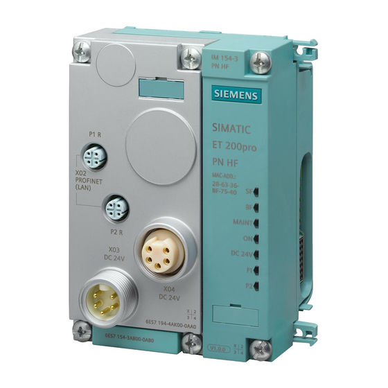
Page 216: Profinet Io
P2 LINK: Connection to a switch or controller (green LED) on port 2 ⑩ P2 RX/TX: Data exchange (yellow LED) on port 2 ⑪ P2 FO: Status of the FO path (yellow LED) on port 2 ET 200pro distributed I/O system Operating Instructions, 03/2013, A5E00335544-08... - Page 217 Check whether the bus cable to the • IO controller is interrupted. The preset configuration of ET 200pro does Check the ET 200pro configuration to see not match the actual ET 200pro configuration. whether a module missing or defective, or whether a non-configured module is inserted.
- Page 218 The green 24 V DC LED is lit when the 2L+ load voltage supply is connected. If the LED is not lit, check to see if the power supply is switched on and the fuse is functioning. ET 200pro distributed I/O system Operating Instructions, 03/2013, A5E00335544-08...
-
Page 219: Diagnostic Messages Of The Electronic Modules
The I/O device generates interrupts as a reaction to specific error events. Interrupts are evaluated based on the I/O controller used. Evaluating interrupts with I/O controllers The ET 200pro supports the following interrupts ● Diagnostic interrupts ● Process interrupts ● Swapping interrupts... - Page 220 Triggering a swapping interrupt The CPU interrupts the user program and processes the diagnostics block OB 83. The interrupt triggering event is logged in the start information of OB 83. ET 200pro distributed I/O system Operating Instructions, 03/2013, A5E00335544-08...
-
Page 221: Maintenance Alarms
The affected fiber-optic cable must be FO-LED is lit demanded reserve of 0 dB immediately replaced to prevent total failure of the PROFINET devices. These diagnostic messages are deleted automatically after 1 second. ET 200pro distributed I/O system Operating Instructions, 03/2013, A5E00335544-08... - Page 222 The maintenance information is generated in with the following system alarms: ● Maintenance required, identified by a yellow wrench per port. ● Maintenance demanded, identified by an orange wrench per port. ET 200pro distributed I/O system Operating Instructions, 03/2013, A5E00335544-08...
-
Page 223: Diagnostics In Step 7
"RDREC" from the IO device (system functions/system function blocks) STEP 7 SFB 54 Receiving interrupts from For SFBs, refer to online help "RALRM" the IO device (system functions/system function blocks) ET 200pro distributed I/O system Operating Instructions, 03/2013, A5E00335544-08... -
Page 224: Channel Diagnostics
For the IM 154-4 PN High Feature interface module, the following manufacturer-specific diagnostics in the USI are signaled. ● Interruption of the ET 200pro backplane bus: USI = W#16#0001 ● Incorrect module combination: USI = W#16#0002 USI structure = W#16#0001... - Page 225 W#16#0002 Manufacturer-specific diagnostics for incorrect module combinations The slot number at which the incorrect combination was configured. Slot number B#16#00 to B#16#11 See also Error types for electronic modules (Page 226) ET 200pro distributed I/O system Operating Instructions, 03/2013, A5E00335544-08...
-
Page 226: Error Types For Electronic Modules
• too low 10101 Reference channel Measuring line for compensation Correct the process wiring error interrupted Data record DS2 incorrect Check data record DS2 Timeout for "Dynamic ref. temp." Send DS2 ET 200pro distributed I/O system Operating Instructions, 03/2013, A5E00335544-08... -
Page 227: Interruption Of The Et 200Pro Backplane Bus
9.2.5.4 Interruption of the ET 200pro backplane bus Separate diagnostics for bus interruption: USI = W#16#0001 If the ET 200pro does not start up, the causes can include: ● One or several missing modules ● Terminating module missing ● Number of modules exceeds maximum configuration ●... -
Page 228: Incorrect Module Combination
● Number of modules exceeds maximum configuration ● Faulty backplane bus, e.g. defective bus module Note If one module is missing (gap) and the ET 200pro is powered on, the startup of the IO device will fail. 9.2.5.7 Failure of the load voltage from the power module... -
Page 229: Stop Of The Io Controller And Recovery Of The Io Device
After the recovery of an IO device, call SFB 52 to read data record E00C . This record contains all diagnostic data for the slots assigned to an IO controller in a device. ET 200pro distributed I/O system Operating Instructions, 03/2013, A5E00335544-08... -
Page 230: Led Display On The Power, Electronic And Pneumatic Interface Modules
To correct or avoid errors DC24V Load voltage 2L+ present at the power module. Load voltage 2L+ missing at the Switch on the load voltage 2L+. power module. Check the fuse. * irrelevant ET 200pro distributed I/O system Operating Instructions, 03/2013, A5E00335544-08... -
Page 231: Led Displays On The Pm-O Outgoing Module
GE error LED Table 9- 10 Error display on the PM-O DC 2x24V outgoing module GE LED Meaning Remedy 1L+ electronic/encoder supply is short- Check the interconnection for a short circuited circuit. ET 200pro distributed I/O system Operating Instructions, 03/2013, A5E00335544-08... -
Page 232: Led Display At The Electronic Module
Status error/channel fault indicator for 8-channel digital High Feature electronic modules (green/red LEDs) Channel fault display of 4-channel analog electronic modules (red LEDs) 1 input/output per circular socket; the top LED display is used. ET 200pro distributed I/O system Operating Instructions, 03/2013, A5E00335544-08... - Page 233 Inverse connection module. ① GE: Group error (red LED) ② Status indicator of 4-channel digital electronic modules (green LEDs) Status error/channel fault indicator for 4-channel digital High Feature electronic modules (green/red LEDs) ET 200pro distributed I/O system Operating Instructions, 03/2013, A5E00335544-08...
- Page 234 CM IO 8 x M12P, CM IO 8 x M12D and CM IO 8 x M8 connection modules. ① GE: Group error (red LED) ② Status indicator of digital electronic modules (green LEDs) Status error/channel fault indicator for digital High Feature electronic modules (green/red LEDs) ET 200pro distributed I/O system Operating Instructions, 03/2013, A5E00335544-08...
- Page 235 Status indicator of 8-channel digital electronic modules (green LEDs) 1 input/output per channel. Figure 9-14 LED display on the connection module CM IO 2 x M12 and CM IO 1 x 23 ET 200pro distributed I/O system Operating Instructions, 03/2013, A5E00335544-08...
- Page 236 Check the wiring. Short-circuit at the outputs Check the wiring. On (green LED) Input/output enabled at channel X1, X2, X3, or X4 Output enabled at channel X5, X6, X7, or X8 ET 200pro distributed I/O system Operating Instructions, 03/2013, A5E00335544-08...
- Page 237 No parameters or faulty parameters Check the parameter settings. Short-circuit at the encoder supply Check the wiring. Channel fault occurred On (red LED) Channel fault at the input/output of channel X1, X2, X3 or X4 ET 200pro distributed I/O system Operating Instructions, 03/2013, A5E00335544-08...
-
Page 238: Led Display On The Electronic Interface Module
Remedy Status and error displays Incoming diagnostic message Analyze the diagnostic data. No parameters or faulty Check the parameter settings. parameters On (green LED) Valve 0.0 (OUT0) to 1.7 (OUT15) enabled ET 200pro distributed I/O system Operating Instructions, 03/2013, A5E00335544-08... -
Page 239: General Technical Data
10.1 Standards and approvals Introduction Contents of general technical specifications: ● The standards and test values which the ET 200pro distributed I/O system complies with/satisfies ● The test criteria used to test the ET 200pro distributed I/O system Note Information on the nameplate You will find the current markings and approvals on the nameplate of the respective product. - Page 240 The ET 200pro distributed I/O system satisfies the requirements and criteria of IEC 61131-2 (Programmable Logic Controllers, Part 2: Equipment Requirements and Tests). PROFIBUS standard The ET 200pro distributed I/O system is based on IEC 61784-1: 2010 Ed3 CP 3/1 Use in industrial environments SIMATIC products are designed for use in industrial applications.
- Page 241 The ET 200pro distributed I/O system is intended for use in industrial environments; when used in residential areas, it can affect radio/television reception. If you use the ET 200pro in residential areas, you must ensure observance of the Class B radio interference limit in accordance with EN 55011 regarding the emission of radio interferences.
-
Page 242: Electromagnetic Compatibility
The ET 200pro distributed I/O system meets all requirements of EMC legislation for the European market. This requires that the ET 200pro distributed I/O system complies with the requirements and guidelines for electrical installation. -
Page 243: Shipping And Storage Conditions
10.3 Shipping and storage conditions Shipping and storage conditions The ET 200pro distributed I/O system surpasses the IEC 61131-2 requirements for shipping and storage conditions. The specifications below apply to modules that are transported and stored in their original packaging. -
Page 244: Mechanical And Climatic Environmental Conditions
* The FESTO CPV10 and CPV14 valve terminals deviate from the specified operating temperature range of 0 to 55° C. For the temperature operating range of FESTO valve terminals, refer to the corresponding FESTO Operating Manuals. ET 200pro distributed I/O system Operating Instructions, 03/2013, A5E00335544-08... - Page 245 6ES7144-4FF00-0AB0 4 AI I High Feature 6ES7144-4GF00-0AB0 4 AI RTD High Feature 6ES7144-4JF00-0AB0 4 AI TC High Feature 6ES7144-4PF00-0AB0 4 AO U High Feature 6ES7145-4FF00-0AB0 4 AO I High Feature 6ES7145-4GF00-0AB0 ET 200pro distributed I/O system Operating Instructions, 03/2013, A5E00335544-08...
- Page 246 Type of shock: half-sine according to Shock intensity: 25 g peak value, 6 ms duration IEC 60068-29 Direction of shock: 1000 shock tests in +/- direction at each of the 3 perpendicular axes ET 200pro distributed I/O system Operating Instructions, 03/2013, A5E00335544-08...
-
Page 247: Specifications For Insulation Tests, Protection Class, Degree Of Protection, And Rated Voltage
● IP67: Protection against water when enclosure is immersed at specified pressures over a specified time period (water must not enter the enclosure in any harmful amount) Rated voltage for operation The ET 200pro distributed I/O system operates at the following rated voltage and corresponding tolerance. Rated voltage... - Page 248 General technical data 10.5 Specifications for insulation tests, protection class, degree of protection, and rated voltage ET 200pro distributed I/O system Operating Instructions, 03/2013, A5E00335544-08...
-
Page 249: Connection Modules
● Switched terminating resistor for PROFIBUS DP, set by means of DIP switch ● 6 labels Pin assignment Interface For information on the pin assignment of CM IM DP Direct, refer to the section modules ET 200pro distributed I/O system Operating Instructions, 03/2013, A5E00335544-08... - Page 250 Max. 16 A 2L+ load voltage supply • Note Feed current Maximum permissible load on the internal busbars of ET 200pro: • At 1L+ 5 A • At 2L+ 10 A See also IM 154-1 DP interface module (Page 287)
-
Page 251: Cm Im Dp Ecofast Cu Connection Module For Interface Modules
Connections for the ECOFAST connector: encoder/electronic/load voltage supply and PROFIBUS DP ② DIP switch for terminating resistor ③ DIP switch for setting the PROFIBUS DP address Figure 11-1 Block diagram of CM IM DP ECOFAST Cu for interface modules ET 200pro distributed I/O system Operating Instructions, 03/2013, A5E00335544-08... - Page 252 2L+ load voltage supply • Note Feed current The load on the internal busbars of ET 200pro must not exceed the following values: • At 1L+ 5 A • At 2L+ 10 A See also IM 154-1 DP interface module (Page 287)
-
Page 253: Cm Im Dp M12 Connection Module, 7/8" For Interface Modules
Connection for M12 cable connectors (with pin insert): Feeding of PROFIBUS DP ④ Connection for M12 cable connector (with socket insert): Looping through of PROFIBUS DP ⑤ DIP switch for terminating resistor ⑥ DIP switch for setting the PROFIBUS DP address ET 200pro distributed I/O system Operating Instructions, 03/2013, A5E00335544-08... - Page 254 2L+ load voltage supply • Note Feed current The load on the internal busbars of ET 200pro must not exceed the following values: • At 1L+ 5 A • At 2L+ 10 A See also IM 154-1 DP interface module (Page 287)
-
Page 255: Connection Modules For The Interface Module With Profinet Io
Connection for 7/8" cable connector (with socket insert): Forwarding of encoder/electronic supply, load voltage supply ③ Connection for M12 cable connector (with socket insert): Feed for PROFINET IO ④ Connection for M12 cable connector (with socket insert): Forwarding of PROFINET IO ET 200pro distributed I/O system Operating Instructions, 03/2013, A5E00335544-08... - Page 256 2L+ load voltage supply • Note Feed current The load on the internal busbars of ET 200pro must not exceed the following values: • At 1L+ 5 A • At 2L+ 10 A Example of splitting the feed current ● 8 A are fed in at the connection module of IM 154-4 PN High Feature for the 1L+ electronics/encoder supply.
-
Page 257: Cm Im Pn Pp Cu Connection Module For Interface Module
Block diagram ① Connections for push-pull cable connectors: Encoder/electronic supply, load voltage supply ② Connections for push-pull cable connectors: RJ45 for PROFINET IO Figure 11-2 CM IM PN PP Cu connection module ET 200pro distributed I/O system Operating Instructions, 03/2013, A5E00335544-08... - Page 258 * Observe the permitted current carrying capacity of the cable. Note Feed current The load on the internal busbars of ET 200pro must not exceed the following values: • At 1L+ 5 A • At 2L+ 10 A ET 200pro distributed I/O system...
-
Page 259: Cm Im Pn Pp Fo Connection Module For Interface Modules
① Connections for push-pull cable connectors: Encoder/electronic supply, load voltage supply ② Connections for push-pull cable connectors: SC RJ for PROFINET IO Figure 11-3 CM IM PN PP FO connection module ET 200pro distributed I/O system Operating Instructions, 03/2013, A5E00335544-08... - Page 260 Max. 8 A*, up to 55 °C ambient temperature * Observe the permitted current carrying capacity of the cable. Note Feed current The load on the internal busbars of ET 200pro must not exceed the following values: • At 1L+ 5 A • At 2L+ 10 A Note The CM IM PN PP FO connection module may only be pulled/plugged at zero voltage.
-
Page 261: Connection Modules For Electronic Modules
The pin assignment depends on the electronic module used. View Connection Designation 1. M12 circular socket connector 2. M12 circular socket connector 3. M12 circular socket connector 4. M12 circular socket connector ET 200pro distributed I/O system Operating Instructions, 03/2013, A5E00335544-08... - Page 262 Analog electronic module 4 AI RTD High Feature (6ES7144-4JF00-0AB0) (Page 395) Analog electronic module 4 AO U High Feature (6ES7145-4FF00-0AB0) (Page 408) Analog electronic module 4 AO I High Feature (6ES7145-4GF00-0AB0) (Page 414) ET 200pro distributed I/O system Operating Instructions, 03/2013, A5E00335544-08...
-
Page 263: Cm Io 4 X M12P Connection Module For Electronic Modules
4. M12 circular socket connector Block diagram The figure below shows the block diagram of the connection module CM IO 4 x M12P. Figure 11-5 Block diagram, CM IO 4 x M12P connection module ET 200pro distributed I/O system Operating Instructions, 03/2013, A5E00335544-08... - Page 264 Digital electronic module 4 DO DC 24V/2.0A High Feature (6ES7142-4BD00-0AB0) (Page 350) Digital electronic module 8 DO DC 24V/0.5A (6ES7142-4BF00-0AA0) (Page 355) Digital electronic module 4 DI / 4 DO DC 24V/0.5A (6ES7143-4BF50-0AA0) (Page 361) ET 200pro distributed I/O system Operating Instructions, 03/2013, A5E00335544-08...
-
Page 265: Cm Io 4 X M12 Inverse Connection Module For Electronic Modules
The pin assignment depends on the electronic module used. View Connection Designation 1. M12 circular socket connector 2. M12 circular socket connector 3. M12 circular socket connector 4. M12 circular socket connector ET 200pro distributed I/O system Operating Instructions, 03/2013, A5E00335544-08... - Page 266 45 x 130 x 39 Weight Approx. 300 g See also Digital electronic module 4 DO DC 24V/2.0A (6ES7142-4BD00-0AA0) (Page 344) Digital electronic module 4 DO DC 24V/2.0A High Feature (6ES7142-4BD00-0AB0) (Page 350) ET 200pro distributed I/O system Operating Instructions, 03/2013, A5E00335544-08...
-
Page 267: Cm Io 8 X M12 Connection Module For Electronic Modules
8. M12 circular socket connector Block diagram The figure below shows the block diagram of the connection module CM IO 8 x M12. Figure 11-7 Block diagram, CM IO 8 x M12 connection module ET 200pro distributed I/O system Operating Instructions, 03/2013, A5E00335544-08... - Page 268 Digital electronic module 8 DI DC 24V High Feature (6ES7141-4BF00-0AB0) (Page 335) Digital electronic module 8 DO DC 24V/0.5A (6ES7142-4BF00-0AA0) (Page 355) Digital electronic module 4 DI / 4 DO DC 24V/0.5A (6ES7143-4BF50-0AA0) (Page 361) ET 200pro distributed I/O system Operating Instructions, 03/2013, A5E00335544-08...
-
Page 269: Cm Io 8 X M12P Connection Module For Electronic Modules
8. M12 circular socket connector Block diagram The figure below shows the block diagram of the connection module CM IO 8 x M12P. Figure 11-8 Block diagram, CM IO 8 x M12P connection module ET 200pro distributed I/O system Operating Instructions, 03/2013, A5E00335544-08... - Page 270 Digital electronic module 8 DI DC 24V High Feature (6ES7141-4BF00-0AB0) (Page 335) Digital electronic module 8 DO DC 24V/0.5A (6ES7142-4BF00-0AA0) (Page 355) Digital electronic module 4 DI / 4 DO DC 24V/0.5A (6ES7143-4BF50-0AA0) (Page 361) ET 200pro distributed I/O system Operating Instructions, 03/2013, A5E00335544-08...
-
Page 271: Cm Io 8 X M12D Connection Module For Electronic Modules
8. M12 circular socket connector Block diagram The block diagram below relates to the CM IO 8 x M12D connection module. Figure 11-9 Block diagram, CM IO 8 x M12D connection module ET 200pro distributed I/O system Operating Instructions, 03/2013, A5E00335544-08... - Page 272 45 x 130 x 39 Weight Approx. 305 g See also Digital electronic module 16 DI DC 24V (6ES7141-4BH00-0AA0) (Page 340) Digital electronic module 4 DIO / 4 DO DC 24V/0.5A (6ES7143-4BF00-0AA0) (Page 369) ET 200pro distributed I/O system Operating Instructions, 03/2013, A5E00335544-08...
-
Page 273: Cm Io 8 X M8 Connection Module For Electronic Modules
8. M8 circular socket connector Block diagram The figure below shows the block diagram of CM IO 8 x M8 connection module. Figure 11-10 Block diagram CM IO 8 x M8 ET 200pro distributed I/O system Operating Instructions, 03/2013, A5E00335544-08... - Page 274 Digital electronic module 4 DO DC 24V/2.0A High Feature (6ES7142-4BD00-0AB0) (Page 350) Digital electronic module 8 DO DC 24V/0.5A (6ES7142-4BF00-0AA0) (Page 355) Digital electronic module 4 DI / 4 DO DC 24V/0.5A (6ES7143-4BF50-0AA0) (Page 361) ET 200pro distributed I/O system Operating Instructions, 03/2013, A5E00335544-08...
-
Page 275: Cm Io 2 X M12 Connection Module For Electronic Modules
● 2 labels and 1 module tag Pin assignment The pin assignment depends on the electronic module used. View Connection Designation 1. M12 circular socket connector 2. M12 circular socket connector ET 200pro distributed I/O system Operating Instructions, 03/2013, A5E00335544-08... - Page 276 Digital electronic module 4 DO DC 24V/2.0A (6ES7142-4BD00-0AA0) (Page 344) Digital electronic module 8 DO DC 24V/0.5A (6ES7142-4BF00-0AA0) (Page 355) Digital electronic module 4 DI / 4 DO DC 24V/0.5A (6ES7143-4BF50-0AA0) (Page 361) ET 200pro distributed I/O system Operating Instructions, 03/2013, A5E00335544-08...
-
Page 277: Cm Io 1 X M23 Connection Module For Electronic Modules
● 1 M23 circular socket connectors (12-pin) for connection of one actuator/sensor distributor ● 1 label and 1 module tag Pin assignment The pin assignment depends on the electronic module used. View Connection Designation 1. M23 circular socket connector ET 200pro distributed I/O system Operating Instructions, 03/2013, A5E00335544-08... - Page 278 Digital electronic module 4 DO DC 24V/2.0A (6ES7142-4BD00-0AA0) (Page 344) Digital electronic module 8 DO DC 24V/0.5A (6ES7142-4BF00-0AA0) (Page 355) Digital electronic module 4 DI / 4 DO DC 24V/0.5A (6ES7143-4BF50-0AA0) (Page 361) ET 200pro distributed I/O system Operating Instructions, 03/2013, A5E00335544-08...
-
Page 279: Connection Modules For Power Modules
Technical specifications Dimensions and weight Dimensions W x H x D (mm) 45 x 130 x 100 Weight Approx. 140 g Currents Feed current 16 A 2L+ load voltage supply • ET 200pro distributed I/O system Operating Instructions, 03/2013, A5E00335544-08... - Page 280 Connection modules 11.4 Connection modules for power modules Note Feed current The load on the internal busbars of ET 200pro must not exceed the following values: • At 1L+ 5 A • At 2L+ 10 A ET 200pro distributed I/O system...
-
Page 281: Cm Pm-E Ecofast Connection Module For Power Modules
Technical specifications Dimensions and weight Dimensions W x H x D (mm) 45 x 130 x 60 Weight Approx. 125 g Currents Feed current 10 A 2L+ load voltage supply • ET 200pro distributed I/O system Operating Instructions, 03/2013, A5E00335544-08... -
Page 282: Cm Pm-E 7/8" Connection Module For Power Modules
Technical specifications Technical specifications Dimensions and weight Dimensions W x H x D (mm) 45 x 130 x 48 Weight Approx. 120 g Currents Feed current 2L+ load voltage supply • ET 200pro distributed I/O system Operating Instructions, 03/2013, A5E00335544-08... -
Page 283: Cm Pm Pp Connection Module For Power Modules
● Can be plugged in and attached with screws to the power module. ● Connecting the 1L+ electronic/encoder supply and the 2L+ load voltage supply using a push-pull cable connector. 2L+ is fed into the ET 200pro. 1L+ is only looped through from socket to socket. - Page 284 * Observe the permitted current carrying capacity of the cable. Note Feed current The load on the internal busbars of ET 200pro must not exceed the following values: • At 2L+ 10 A ET 200pro distributed I/O system Operating Instructions, 03/2013, A5E00335544-08...
-
Page 285: Cm Pm-O Pp Connection Module For The Pm-O Outgoing Module
Regenerative feedback of 1L+/2L+ can lead to undefined system behavior and system damage. For this reason, to prevent damage, never feed back energy of the 1L+ electronic/encoder supply and the 2L+ load voltage supply. ET 200pro distributed I/O system Operating Instructions, 03/2013, A5E00335544-08... - Page 286 Approx. 110 g Currents Discharge currents Max. 2 A 1L+ electronics/encoder supply • Max. 6 A 2L+ load voltage supply • Note Capacitive loads can influence the switching behavior of the F-switch. ET 200pro distributed I/O system Operating Instructions, 03/2013, A5E00335544-08...
-
Page 287: Interface Modules
● The module supplies the ET 200pro via the connection module with the 1L+ encoder/electronic supply and the 2L+ load voltage supply. ● The PROFIBUS DP address of ET 200pro can be set by means of the connection module. ● The connection module can be used to activate/deactivate the terminating resistor of PROFIBUS DP. - Page 288 Ground for electronics/encoder supply Load voltage supply Ground for load voltage supply Screw terminal for forwarding X02 electronics/encoder supply Ground for electronics/encoder supply Load voltage supply Ground for load voltage supply ET 200pro distributed I/O system Operating Instructions, 03/2013, A5E00335544-08...
- Page 289 2L+ load voltage supply Forwarding X02 PROFIBUS DP signal A PROFIBUS DP signal B 1L+ electronics/encoder supply Ground for electronics/encoder supply 1M Ground for load voltage supply 2M 2L+ load voltage supply ET 200pro distributed I/O system Operating Instructions, 03/2013, A5E00335544-08...
- Page 290 ** We recommend that you connect the functional earth via the M12 thread (because it has a larger surface area than terminal 5). ET 200pro distributed I/O system Operating Instructions, 03/2013, A5E00335544-08...
- Page 291 Connections for the electronics/encoder supply and load voltage supply ② Connections for PROFIBUS DP ③ DIP switch for terminating resistor ④ DIP switch for the PROFIBUS DP address Figure 12-1 Block diagram IM 154-1 DP ET 200pro distributed I/O system Operating Instructions, 03/2013, A5E00335544-08...
- Page 292 (1L+) Yes; against destruction Reverse polarity protection • Yes; with replaceable fuses Short-circuit protection • Max. 5 A; per ET 200pro Feed current 1L+ • Rated load voltage 2L+ 24 V DC(integrated power module) Yes; against destruction Reverse polarity protection •...
- Page 293 CM IM DP ECOFAST Cu connection module for interface modules (Page 251) CM IM DP M12 connection module, 7/8" for interface modules (Page 253) Electrical Configuration of ET 200pro (Page 71) ET 200pro distributed I/O system Operating Instructions, 03/2013, A5E00335544-08...
-
Page 294: Im 154-2 Dp High Feature Interface Module
● The module supplies the ET 200pro via the connection module with the 1L+ encoder/electronic supply and the 2L+ load voltage supply. ● The PROFIBUS DP address of ET 200pro can be set by means of the connection module. ● The connection module can be used to activate/deactivate the terminating resistor of PROFIBUS DP. - Page 295 Ground for electronics/encoder supply Load voltage supply Ground for load voltage supply Screw terminal for forwarding X02 electronics/encoder supply Ground for electronics/encoder supply Load voltage supply Ground for load voltage supply ET 200pro distributed I/O system Operating Instructions, 03/2013, A5E00335544-08...
- Page 296 2L+ load voltage supply Forwarding X02 PROFIBUS DP signal A PROFIBUS DP signal B 1L+ electronics/encoder supply Ground for electronics/encoder supply 1M Ground for load voltage supply 2M 2L+ load voltage supply ET 200pro distributed I/O system Operating Instructions, 03/2013, A5E00335544-08...
- Page 297 ** We recommend that you connect the functional earth via the M12 thread (because it has a larger surface area than terminal 5). ET 200pro distributed I/O system Operating Instructions, 03/2013, A5E00335544-08...
- Page 298 CM IM DP Direct as optional connection module. ① Connections for the electronics/encoder supply and load voltage supply ② Connections for PROFIBUS DP ③ DIP switch for terminating resistor ④ DIP switch for the PROFIBUS DP address ET 200pro distributed I/O system Operating Instructions, 03/2013, A5E00335544-08...
- Page 299 (1L+) Yes; against destruction Reverse polarity protection • Yes; with replaceable fuses Short-circuit protection • Max. 5 A; per ET 200pro Feed current 1L+ • Rated load voltage 2L+ 24 V DC(integrated power module) Yes; against destruction Reverse polarity protection •...
- Page 300 See also chapter Parameter assignment dependencies (Page 304). See also Electrical Configuration of ET 200pro (Page 71) Connection module CM IM DP Direct for interface modules (Page 249) CM IM DP ECOFAST Cu connection module for interface modules (Page 251) CM IM DP M12 connection module, 7/8"...
-
Page 301: Overview Of Parameters Of The Interface Module
ET 200pro Disable • Enable • This diagnostics function can be disabled. Parameters for the integrated power module Parameters Value range Scope Load voltage diagnostics ET 200pro Disable • Enable • ET 200pro distributed I/O system Operating Instructions, 03/2013, A5E00335544-08... -
Page 302: Description Of The Interface Module Parameters
Operation with preset <> actual configuration If this parameter is enabled and ● you hot-swap an electronic module, this will not cause a failure of the ET 200pro station. ● the preset and actual configurations do not match, ET 200pro can still exchange data with the DP master. - Page 303 If you enable this parameter, the system generates diagnostic data when it detects a missing load voltage 2L+. Option handling This parameter can be used to enable or disable option handling for the entire ET 200pro. ET 200pro distributed I/O system Operating Instructions, 03/2013, A5E00335544-08...
-
Page 304: Parameter Assignment Dependencies
Not possible Not possible ● ● ● ● ● ● ● ET 200pro motor starter, Appendix D.4, Device parameters See Manual DPV1 mode IM154-1/-2... properties For parameter assignment with... Option handling Y-link Configuration ET 200pro motor starter ET 200pro, all other >... -
Page 305: Interface Modules For Profinet Io
● The module interconnects ET 200pro with PROFINET IO. ● The module prepares the data for the connected electronic modules. ● The module supplies the ET 200pro via the connection module with the 1L+ encoder/electronic supply and the 2L+ load voltage supply. - Page 306 Otherwise, IRT and RT configured IO devices may fail if the sync master fails. For further information about configuring synchronized PROFINET devices in sync domains, refer to the STEP 7 online help and the PROFINET System Description (http://support.automation.siemens.com/WW/view/en/19292127) manual. ET 200pro distributed I/O system Operating Instructions, 03/2013, A5E00335544-08...
- Page 307 IO devices is possible at a particular time via the IO device port. However, only the changing device that is currently being communicated with may be physically connected to the changing port. ET 200pro distributed I/O system Operating Instructions, 03/2013, A5E00335544-08...
- Page 308 Spare part replacement for IM 154-4 PN High Feature If a spare part replacement is necessary, an IO device in operation must be reset to the factory settings by using "Reset to factory settings". ET 200pro distributed I/O system Operating Instructions, 03/2013, A5E00335544-08...
- Page 309 CM IM PN PP FO alarm: alarm: 6ES7154-4AB10- Preset/actual Preset/actual 0AB0 discrepancy discrepancy ● Cyclic data exchange: SF LED off, BF-LED off ● No cyclic data exchange: SF LED off, BF-LED flashes ET 200pro distributed I/O system Operating Instructions, 03/2013, A5E00335544-08...
- Page 310 Resetting to factory settings pertains only to the interface module. When a reset to factory settings is performed, other modules in the station assume the configured substitute value behavior or become de-energized. ET 200pro distributed I/O system Operating Instructions, 03/2013, A5E00335544-08...
- Page 311 The most recent firmware versions are available from your Siemens representative or from the Internet (http://www.siemens.com/automation/service&support). The following firmware versions are required for operating non-failsafe I/O modules on the...
- Page 312 X03 DC 24V for feeding X04 DC 24V for looping Ground for load voltage supply 2M Ground for electronics/encoder supply 1M Functional earth (FE) 1L+ electronics/encoder supply 2L+ load voltage supply ET 200pro distributed I/O system Operating Instructions, 03/2013, A5E00335544-08...
- Page 313 Transmit Data+ TD Receive Data+ RD Transmit Data- TD_N Receive Data- RD_N Receive Data+ RD Transmit Data+ TD Ground GND Ground GND Receive Data- RD_N Transmit Data- TD_N Ground GND Ground GND ET 200pro distributed I/O system Operating Instructions, 03/2013, A5E00335544-08...
- Page 314 2L+ load voltage supply Ground for load voltage supply 2M Functional earth (FE) Push-pull cable connector (SC RJ) X02 PN1 for feeding PROFINET X02 PN2 for forwarding PROFINET TX (Transmit Data) RX (Receive Data) ET 200pro distributed I/O system Operating Instructions, 03/2013, A5E00335544-08...
- Page 315 Connection for the electronics/encoder supply and load voltage supply (forwarding) ③ Connection for PROFINET IO (feed) ④ Connection for PROFINET IO (forwarding) Figure 12-2 IM 154-4 PN High Feature block diagram ET 200pro distributed I/O system Operating Instructions, 03/2013, A5E00335544-08...
- Page 316 (1L+) Yes; against destruction Reverse polarity protection • Yes; with replaceable fuses Short-circuit protection • Max. 5 A; per ET 200pro Feed current 1L+ • Rated load voltage 2L+ 24 V DC(integrated power module) Yes; against destruction Reverse polarity protection •...
- Page 317 Yellow LED (RX/TX); one LED per feed (P1) and Transmitting/receiving via network • forwarding (P2) of PROFINET IO Yellow LED (FO); one LED per feed (P1) and Diagnostics • forwarding (P2) of PROFINET IO ET 200pro distributed I/O system Operating Instructions, 03/2013, A5E00335544-08...
-
Page 318: Overview Of Parameters Of The Interface Module
• Enable • 12.2.3 Description of the interface module parameters Load voltage diagnostics If you enable this parameter, the system generates diagnostic data when it detects a missing load voltage 2L+. ET 200pro distributed I/O system Operating Instructions, 03/2013, A5E00335544-08... -
Page 319: Power Modules
View of screw terminal X01 Designation Feeding and forwarding X01 2L+ load voltage supply (feed) Ground for load voltage supply 2M (feed) 2L+ load voltage supply (forwarding) Ground for load voltage supply 2M (forwarding) ET 200pro distributed I/O system Operating Instructions, 03/2013, A5E00335544-08... - Page 320 Pin assignment of the load voltage supply at connection module CM PM 7/8" View of the 7/8" connector X01 Terminal Designation Feed for X01 Ground for load voltage supply 2M Not assigned Not assigned Not assigned 2L+ load voltage supply ET 200pro distributed I/O system Operating Instructions, 03/2013, A5E00335544-08...
- Page 321 * Terminals 1 and 2 are jumpered between X01 IN and X02 OUT in the connection module. Block diagram The figure below shows the block diagram of the power module PM-E ① Connections of the 2L+ load voltage supply ET 200pro distributed I/O system Operating Instructions, 03/2013, A5E00335544-08...
- Page 322 • Yes; against destruction Reverse polarity protection • Max. current carrying capacity (up to 55° C) 10 A; on the internal busbars of ET 200pro Yes; replaceable fuse in the power module Short-circuit protection • Current consumption From load voltage 2L+ Max.
- Page 323 See also Placement of PM-E power module (Page 39) Electrical Configuration of ET 200pro (Page 71) Connecting the Power Module with the CM PM-E Direct Connection Module (Page 130) Connecting the Power Module with the CM PM-E ECOFAST Connection Module (Page 132) Connecting the Power Module with the CM PM-E 7/8"...
-
Page 324: Pm-O Dc 2X24V Outgoing Module
Ground for load voltage supply 2M Functional earth Electronics/encoder supply and load voltage supply of 1L+ electronics/encoder supply Ground for electronics/encoder supply 1M 2L+ load voltage supply Ground for load voltage supply 2M Functional earth ET 200pro distributed I/O system Operating Instructions, 03/2013, A5E00335544-08... - Page 325 Power modules 13.2 PM-O DC 2x24V outgoing module Block diagram The figure below shows the block diagram of the PM-O DC 2x24V outgoing module. ET 200pro distributed I/O system Operating Instructions, 03/2013, A5E00335544-08...
- Page 326 • Yes; against destruction Reverse polarity protection • Max. current carrying capacity (up to 55° C) 10 A; on the internal busbars of ET 200pro Yes, electronic 1L+ short circuit • Yes, via a replaceable fuse in the upstream power 2L+ short circuit protection •...
-
Page 327: Parameter Overview Of Power/Outgoing Module
2L+. Diagnostics for short circuit to M If you enable this parameter, the system generates diagnostic data when an external short- circuit of the 1L+ electronic/encoder supply to M occurs. ET 200pro distributed I/O system Operating Instructions, 03/2013, A5E00335544-08... - Page 328 Power modules 13.4 Parameter description for power/outgoing module ET 200pro distributed I/O system Operating Instructions, 03/2013, A5E00335544-08...
-
Page 329: Digital Electronic Modules
CM IO 4 x M12P connection modules. View of circular connector Terminal Assignment X1 to X4 24 V encoder supply U (provided by ET 200pro for the connected encoder) Input signal DI : Connector X1 Input signal DI : Connector X2... - Page 330 CM IO 8 x M12P connection modules. View of circular connector Terminal Assignment X1 to X8 24 V encoder supply U (provided by ET 200pro for the connected encoder) Not assigned Encoder supply ground 1M Input signal DI : Connector X1...
- Page 331 Input signal DI Input signal DI Input signal DI Input signal DI Input signal DI Input signal DI Encoder supply ground 1M Encoder supply ground 1M 24V encoder supply U Functional earth (FE) ET 200pro distributed I/O system Operating Instructions, 03/2013, A5E00335544-08...
- Page 332 14.1 Digital electronic module 8 DI DC 24V (6ES7141-4BF00-0AA0) Block diagram The figure below shows the block diagram of the 8 DI DC 24V. Figure 14-1 Block diagram 8 DI DC 24V ET 200pro distributed I/O system Operating Instructions, 03/2013, A5E00335544-08...
- Page 333 Permissible quiescent current • Encoder supply Number of encoder supplies Total current up to 55 °C Max. 1 A Short-circuit protection Yes; each module, electronic Min. 1.4 A Response threshold • ET 200pro distributed I/O system Operating Instructions, 03/2013, A5E00335544-08...
- Page 334 Connection module CM IO 4 x M12 for electronic modules (Page 261) CM IO 8 x M12 connection module for electronic modules (Page 267) Response times of digital input modules (Page 508) ET 200pro distributed I/O system Operating Instructions, 03/2013, A5E00335544-08...
-
Page 335: Digital Electronic Module 8 Di Dc 24V High Feature (6Es7141-4Bf00-0Ab0)
CM IO 4 x M12 and CM IO 4 x M12P connection modules. View of circular connector Terminal Assignment X1 to X4 24 V encoder supply U (provided by ET 200pro for the connected encoder) Input signal DI : Connector X1 Input signal DI... - Page 336 CM IO 8 x M12 and CM IO 8 x M12P connection modules. View of circular connector Terminal Assignment X1 to X8 24 V encoder supply U (provided by ET 200pro for the connected encoder) Not assigned Encoder supply ground 1M Input signal DI...
- Page 337 14.2 Digital electronic module 8 DI DC 24V High Feature (6ES7141-4BF00-0AB0) Block diagram The figure below shows the block diagram of 8 DI DC 24V High Feature. Figure 14-2 8 DI DC 24V High Feature block diagram ET 200pro distributed I/O system Operating Instructions, 03/2013, A5E00335544-08...
- Page 338 Assignable hardware interrupt • Diagnostic functions Red LED (SF) Group error display • Red LED, per channel; combined with green Channel error display • status LED Diagnostic information can be read • ET 200pro distributed I/O system Operating Instructions, 03/2013, A5E00335544-08...
- Page 339 Max. 2 mA Permissible quiescent current • See also Connection module CM IO 4 x M12 for electronic modules (Page 261) CM IO 8 x M12 connection module for electronic modules (Page 267) ET 200pro distributed I/O system Operating Instructions, 03/2013, A5E00335544-08...
-
Page 340: Digital Electronic Module 16 Di Dc 24V (6Es7141-4Bh00-0Aa0)
The table below shows the pin assignment of the 16 DI DC 24V on the CM IO 8 x M12D connection module. View of circular connector Terminal Assignment X1 to X4 24 V encoder supply U (provided by ET 200pro for the connected encoder) Input signal DI : Connector X1 Input signal DI : Connector X2... - Page 341 14.3 Digital electronic module 16 DI DC 24V (6ES7141-4BH00-0AA0) Block diagram The figure below shows the block diagram of the 16 DI DC 24V. Figure 14-3 Block diagram 16 DI DC 24V ET 200pro distributed I/O system Operating Instructions, 03/2013, A5E00335544-08...
- Page 342 Permissible quiescent current • Encoder supply Number of encoder supplies Total current up to 55 °C Max. 1 A Short-circuit protection Yes; each module, electronic Min. 1.4 A Response threshold • ET 200pro distributed I/O system Operating Instructions, 03/2013, A5E00335544-08...
- Page 343 (function module FM) as the module class in byte x+5. See Diagnostic interrupt, byte x+4 to x+7 (Page 209). See also CM IO 8 x M12D connection module for electronic modules (Page 271) ET 200pro distributed I/O system Operating Instructions, 03/2013, A5E00335544-08...
-
Page 344: Digital Electronic Module 4 Do Dc 24V/2.0A (6Es7142-4Bd00-0Aa0)
More detailed information is available in the Appendix in the chapter Fail-safe disconnection of ET 200pro standard output modules (Page 267). Pin assignment of connection modules CM IO 4 x M12 and CM IO 4 x M12P The table below shows the pin assignment of the 4 DO DC 24V/2.0A on the CM IO 4 x M12 and CM IO 4 x M12P connection modules. - Page 345 Channels 1 and 3 are only allowed to be connected to one circular socket connector each: • Channel 1 to circular socket connector X1 or X2. • Channel 3 to circular socket connector X3 or X4. ET 200pro distributed I/O system Operating Instructions, 03/2013, A5E00335544-08...
- Page 346 : Connector X1 Output signal DQ : Connector X1 Output signal DQ : Connector X1 Not assigned Not assigned Ground for load voltage supply 2M Functional earth (FE) Connector X2 is not assigned ET 200pro distributed I/O system Operating Instructions, 03/2013, A5E00335544-08...
- Page 347 Ground for load voltage supply 2M Not assigned Functional earth (FE) Block diagram The figure below shows the block diagram of the 4 DO DC 24V/2.0A. Figure 14-4 Block diagram 4 DO DC 24V ET 200pro distributed I/O system Operating Instructions, 03/2013, A5E00335544-08...
- Page 348 Output current With "1" signal • Max. 0.5 mA With "0" signal (residual current) • Wiring 2 outputs in parallel For performance increase • Supported For redundant control of a load • ET 200pro distributed I/O system Operating Instructions, 03/2013, A5E00335544-08...
- Page 349 Between different electric circuits • See also Fail-safe shutdown of the ET 200pro Standard edition modules (Page 524) Connection module CM IO 4 x M12 for electronic modules (Page 261) CM IO 4 x M12 Inverse connection module for electronic modules (Page 265)
-
Page 350: Digital Electronic Module 4 Do Dc 24V/2.0A High Feature (6Es7142-4Bd00-0Ab0)
More detailed information is available in the Appendix in the chapter Fail-safe disconnection of ET 200pro standard output modules (Page 524). Pin assignment of connection modules CM IO 4 x M12 and CM IO 4 x M12P The table below shows the pin assignment of the 4 DO DC 24V/2.0A High Feature on the CM IO 4 x M12 and CM IO 4 x M12P connection modules. - Page 351 Channels 1 and 3 are only allowed to be connected to one circular socket connector each: • Channel 1 to circular socket connector X1 or X2. • Channel 3 to circular socket connector X3 or X4. ET 200pro distributed I/O system Operating Instructions, 03/2013, A5E00335544-08...
- Page 352 Connectors X5 to X8 are not assigned Block diagram The figure below shows the block diagram of 4 DO DC 24V/2.0A High Feature. Figure 14-5 Block diagram of 4 DO DC 24V/2.0A High Feature ET 200pro distributed I/O system Operating Instructions, 03/2013, A5E00335544-08...
- Page 353 75 V DC, 60 V AC Between different electric circuits • Isolation Isolation tested 500 V DC Status, interrupts, diagnostics Status display Green LED, per channel Interrupts Configurable Diagnostic interrupt • ET 200pro distributed I/O system Operating Instructions, 03/2013, A5E00335544-08...
- Page 354 See also Digital electronic modules (Page 329) CM IO 4 x M12 Inverse connection module for electronic modules (Page 265) CM IO 8 x M12 connection module for electronic modules (Page 267) ET 200pro distributed I/O system Operating Instructions, 03/2013, A5E00335544-08...
-
Page 355: Digital Electronic Module 8 Do Dc 24V/0.5A (6Es7142-4Bf00-0Aa0)
More detailed information is available in the Appendix in the chapter Fail-safe disconnection of ET 200pro standard output modules (Page 524). Pin assignment of connection modules CM IO 4x M12 and CM IO 4x M12P The table below shows the pin assignment of the 8 DO DC 24V/0.5A on the CM IO 4 x M12 and CM IO 4 x M12P connection modules. - Page 356 Output signal DQ : Connector X5 Output signal DQ : Connector X6 Output signal DQ : Connector X7 Output signal DQ : Connector X8 Functional earth (FE) ① 3-core copper cable ET 200pro distributed I/O system Operating Instructions, 03/2013, A5E00335544-08...
- Page 357 Output signal DQ Output signal DQ Output signal DQ Output signal DQ Output signal DQ Ground for load voltage supply 2M Ground for load voltage supply 2M Not assigned Functional earth (FE) ET 200pro distributed I/O system Operating Instructions, 03/2013, A5E00335544-08...
- Page 358 14.6 Digital electronic module 8 DO DC 24V/0.5A (6ES7142-4BF00-0AA0) Block diagram The figure below shows the block diagram of the 8 DO DC 24V/0.5A. Figure 14-6 Block diagram 8 DO DC 24V/0.5A ET 200pro distributed I/O system Operating Instructions, 03/2013, A5E00335544-08...
- Page 359 0.5 A With "1" signal • Max. 0.5 mA With "0" signal (residual current) • Wiring 2 outputs in parallel For performance increase • Supported For redundant control of a load • ET 200pro distributed I/O system Operating Instructions, 03/2013, A5E00335544-08...
- Page 360 Between backplane bus and all other circuit • elements Between channels and electronics power • supply Between channels • Permitted potential difference 75 V DC, 60 V AC Between different electric circuits • ET 200pro distributed I/O system Operating Instructions, 03/2013, A5E00335544-08...
-
Page 361: Digital Electronic Module 4 Di / 4 Do Dc 24V/0.5A (6Es7143-4Bf50-0Aa0)
CM IO 4 x M12 and CM IO 4 x M12P. View of circular connector Terminal Assignment X1 to X4 (inputs/outputs) 24 V encoder supply U (from 2L+) (is supplied by the ET 200pro to the connected encoder) Output signal DQ : Connector X1 Output signal DQ : Connector X2... - Page 362 View of circular connector Terminal Assignment Terminal Assignment X1 to X4 (inputs) 24 V encoder supply U (from 2L+) (is supplied by the ET 200pro to the connected encoder) Not assigned Ground 2M Input signal DI : Connector X1 Input signal DI...
- Page 363 View of circular connector Terminal Assignment Terminal Assignment X1 to X4 (inputs) 24 V encoder supply U (from 2L+) (is supplied by the ET 200pro to the connected encoder) Ground 2M Input signal DI : Connector X1 Input signal DI : Connector X2...
- Page 364 Input signal DI Input signal DI Input signal DI Input signal DI 24 V encoder supply U (from 2L+) (is supplied by the ET 200pro to the connected encoder) Not assigned Ground 2M Functional earth (FE) Terminal Assignment X2 (outputs)
- Page 365 Output signal DQ Ground 2M Ground 2M 24 V encoder supply U (from 2L+) (is supplied by the ET 200pro to the connected encoder) Functional earth (FE) Block diagram with CM IO 4 x M12 Figure 14-7 Block diagram 4 DI / 4 DO DC 24V/0.5A for CM IO 4 x M12...
- Page 366 For "1" signal • Input current Typ. 7 mA With "1" signal • Input delay Typ. 3 ms At "0" to "1" transition • Typ. 3 ms At "1" to "0" transition • ET 200pro distributed I/O system Operating Instructions, 03/2013, A5E00335544-08...
- Page 367 • Diagnostic functions Red LED (SF) Group error display • Channel error display • Diagnostic information can be read • Monitoring for Short-circuit encoder supply • Short-circuit at the output • ET 200pro distributed I/O system Operating Instructions, 03/2013, A5E00335544-08...
- Page 368 Between backplane bus and all other circuit • elements Between channels and electronics power • supply Between channels • Permitted potential difference 75 V DC, 60 V AC Between different electric circuits • ET 200pro distributed I/O system Operating Instructions, 03/2013, A5E00335544-08...
-
Page 369: Digital Electronic Module 4 Dio / 4 Do Dc 24V/0.5A (6Es7143-4Bf00-0Aa0)
(rated load voltage 2L+) can be switched off for safety-related operation. More detailed information is available in the Appendix in the chapter Fail-safe disconnection of ET 200pro standard output modules (Page 524). ET 200pro distributed I/O system Operating Instructions, 03/2013, A5E00335544-08... - Page 370 CM IO 8 x M12D. View of circular connector Terminal Assignment X1 to X4 (inputs/outputs) 24 V encoder supply U (provided by ET 200pro for the connected encoder) Not assigned Encoder supply ground 1M Input/output signal DIQ : Connector X1...
- Page 371 14.8 Digital electronic module 4 DIO / 4 DO DC 24V/0.5A (6ES7143-4BF00-0AA0) Block diagram The following figure shows the block diagram of 4 DIO / 4 DO DC 24V/0.5A. Figure 14-8 Block diagram 4 DIO / 4 DO DC 24V/0.5A ET 200pro distributed I/O system Operating Instructions, 03/2013, A5E00335544-08...
- Page 372 Cable length, unshielded Max. 30 m Input voltage 24 V DC Rated value • -3 V to +5 V For "0" signal • 11 V to 30 V For "1" signal • ET 200pro distributed I/O system Operating Instructions, 03/2013, A5E00335544-08...
- Page 373 100 Hz With resistive load • 0.5 Hz With inductive load • 1 Hz With lamp load • Load resistance range 48 Ω Low limit • 4 kΩ High limit • ET 200pro distributed I/O system Operating Instructions, 03/2013, A5E00335544-08...
- Page 374 X1 to X4 powered from 1L+, and X5 to X8 powered from 2L+ In the overload range, the digital output can be activated/deactivated at cyclic intervals applies only to outputs operated on 2L+ potential ET 200pro distributed I/O system Operating Instructions, 03/2013, A5E00335544-08...
-
Page 375: Overview Of Parameters Of The Digital Electronic Modules
* If you use the electronic module with the connection module CM IO 4xM12, channels 4 to 7 are mapped to channels 0 to 3. A precise channel-specific diagnosis "Short-circuit to M" is not therefore possible. ET 200pro distributed I/O system Operating Instructions, 03/2013, A5E00335544-08... - Page 376 Channel Disable • (channels 0 to 3) Enable • Diagnostics: Wire break Disable Channel Disable • (channels 0 to 3) Enable • Substitute values Channel • (channels 0 to 3) • ET 200pro distributed I/O system Operating Instructions, 03/2013, A5E00335544-08...
- Page 377 Parameters for 4 DI / 4 DO DC 24V/0.5A Parameters Value range Default Effective range Reaction to CPU/master STOP Shutdown Module Shutdown • Hold last value • Diagnostics: Short-circuit Disable Module Disable • Enable • ET 200pro distributed I/O system Operating Instructions, 03/2013, A5E00335544-08...
- Page 378 Freely configurable channel 1 Channel • • Freely configurable channel 2 Channel • • Freely configurable channel 3 Channel • • See also Overview of parameters of the digital electronic modules (Page 379) ET 200pro distributed I/O system Operating Instructions, 03/2013, A5E00335544-08...
-
Page 379: Overview Of Parameters Of The Digital Electronic Modules
Diagnostics: Short-circuit to M 24 V encoder supply If this parameter is enabled, the system generates a diagnostics event when it detects a short-circuit of the encoder supply to ground. ET 200pro distributed I/O system Operating Instructions, 03/2013, A5E00335544-08... - Page 380 ● Shutdown: The digital output is de-energized. ● Hold last value: The last value of the digital output remains active. ● Output substitute values: The module outputs a configured substitute value. ET 200pro distributed I/O system Operating Instructions, 03/2013, A5E00335544-08...
- Page 381 If this parameter is enabled, the system generates an "Error" diagnostics when it detects a short-circuit of the encoder supply to ground. See also Overview of parameters of the digital electronic modules (Page 375) ET 200pro distributed I/O system Operating Instructions, 03/2013, A5E00335544-08...
- Page 382 Digital electronic modules 14.10 Overview of parameters of the digital electronic modules ET 200pro distributed I/O system Operating Instructions, 03/2013, A5E00335544-08...
-
Page 383: Analog Electronic Modules
● Diagnostics for short-circuit, diagnostics for wire break per channel (based on the measuring range) ● Hardware interrupt on limit violation at channel 0 ● Permitted common-mode voltage 5 V AC ET 200pro distributed I/O system Operating Instructions, 03/2013, A5E00335544-08... - Page 384 Input signal U -: Connector X1 Input signal U -: Connector X2 Input signal U -: Connector X3 Input signal U -: Connector X4 Functional earth (FE) ① Shielded copper cables ET 200pro distributed I/O system Operating Instructions, 03/2013, A5E00335544-08...
- Page 385 15.1 Analog electronic module 4 AI U High Feature (6ES7144-4FF00-0AB0) Block diagram The figure below shows the block diagram of 4 AI U High Feature. Figure 15-1 Block diagram 4 AI U High Feature ET 200pro distributed I/O system Operating Instructions, 03/2013, A5E00335544-08...
- Page 386 16.667 Integration time in ms • 66.667 66.667 Conversion time in ms • Number of active channels per module x Cycle time in ms • conversion time Response times (see Appendix ET 200pro distributed I/O system Operating Instructions, 03/2013, A5E00335544-08...
- Page 387 Diagnostic functions can be read out • Monitoring for Yes, at 1 V to 5 V Short-circuit • Yes, at 1 V to 5 V Wire break • Isolation Isolation tested with 500 V DC ET 200pro distributed I/O system Operating Instructions, 03/2013, A5E00335544-08...
- Page 388 5 V AC Between the inputs and 1M (U • See also Connection module CM IO 4 x M12 for electronic modules (Page 261) Response times for analog input modules (Page 509) ET 200pro distributed I/O system Operating Instructions, 03/2013, A5E00335544-08...
-
Page 389: Analog Electronic Module 4 Ai I High Feature (6Es7144-4Gf00-0Ab0)
● Diagnostics for encoder supply short-circuit to M per module ● Diagnostics for short-circuit/wire break per channel (based on the measuring range) ● Hardware interrupt on limit violation at channel 0 ● Permitted common-mode voltage 5 V AC ET 200pro distributed I/O system Operating Instructions, 03/2013, A5E00335544-08... - Page 390 -: Connector X4 Functional earth (FE) ① Shielded copper cables Note 2-wire transducer A configuration as 2-wire transducer will destroy the electronic module in case of a short- circuit to encoder supply (U ET 200pro distributed I/O system Operating Instructions, 03/2013, A5E00335544-08...
- Page 391 15.2 Analog electronic module 4 AI I High Feature (6ES7144-4GF00-0AB0) Block diagram The figure below shows the block diagram of 4 AI I High Feature. Figure 15-2 Block diagram, 4 AI I High Feature ET 200pro distributed I/O system Operating Instructions, 03/2013, A5E00335544-08...
- Page 392 16.667 Integration time in ms • 66.667 66.667 Conversion time in ms • Number of active channels per module x Cycle time in ms • conversion time (see Appendix Response times) ET 200pro distributed I/O system Operating Instructions, 03/2013, A5E00335544-08...
- Page 393 Diagnostic functions can be read out • Monitoring for Yes, at 4 to 20 mA Short-circuit to ground (1M) • Yes, at 4 to 20 mA Wire break • Isolation Isolation tested with 500 V DC ET 200pro distributed I/O system Operating Instructions, 03/2013, A5E00335544-08...
- Page 394 5 V AC Between the inputs and 1M (U • See also Connection module CM IO 4 x M12 for electronic modules (Page 261) Response times for analog input modules (Page 509) ET 200pro distributed I/O system Operating Instructions, 03/2013, A5E00335544-08...
-
Page 395: Analog Electronic Module 4 Ai Rtd High Feature (6Es7144-4Jf00-0Ab0)
● Inputs are electrically isolated from encoder voltage supply 1L+ and load voltage supply ● Linearization of the encoder characteristic curves ● Wire break diagnostics per channel (terminals 1 and 3 are monitored for wire break) ET 200pro distributed I/O system Operating Instructions, 03/2013, A5E00335544-08... - Page 396 +: Connector X4 Measuring line M -: Connector X1 Measuring line M -: Connector X2 Measuring line M -: Connector X3 Measuring line M -: Connector X4 Not assigned Functional earth (FE) ET 200pro distributed I/O system Operating Instructions, 03/2013, A5E00335544-08...
- Page 397 Functional earth (FE) ① Shielded copper cables Block diagram The figure below shows the block diagram of the 4 AI RTD High Feature. Figure 15-3 Block diagram 4 AI RTD High Feature ET 200pro distributed I/O system Operating Instructions, 03/2013, A5E00335544-08...
- Page 398 Connection of signal transmitters As 4-wire For resistance • measurement, resistance As 3-wire thermometer As 2-wire Yes, line resistances are also measured Characteristic linearization Yes, can be assigned for Ptxxx, Nixxx ET 200pro distributed I/O system Operating Instructions, 03/2013, A5E00335544-08...
- Page 399 Response Cycle time in ms (see Appendix • conversion time times in the ET 200pro manual) 150 Ω; 300 Ω; 600 Ω; 3000 Ω/15 bit Resolution (including overrange) • Pt100; Ni100; Ni120; Pt200; Ni200; Pt500; Ni500; Pt1000; Ni1000/15 bit + sign...
- Page 400 3 wires in the cable are the same. See also Connection module CM IO 4 x M12 for electronic modules (Page 261) Response times for analog input modules (Page 509) ET 200pro distributed I/O system Operating Instructions, 03/2013, A5E00335544-08...
-
Page 401: Ai Tc High Feature Analog Electronic Module (6Es7144-4Pf00-0Ab0)
● Linearization of the voltage characteristic (conversion of the thermoelectric voltage to a temperature value) ● Smoothing ● Interference frequency suppression ● Various options to compensate for the reference junction temperature ● Overflow and underflow diagnostics ET 200pro distributed I/O system Operating Instructions, 03/2013, A5E00335544-08... - Page 402 * If the M12 compensation connector is being used, the Pt1000 resistance thermometer is already integrated. If an external Pt1000 is connected, a resistance thermometer should be used (where α = 0.003851). ET 200pro distributed I/O system Operating Instructions, 03/2013, A5E00335544-08...
- Page 403 Measuring line negative M- assigned with internal Pt1000 Input signal M -: Connector X1 Functional earth (FE) ① Wire of cable made from thermocouple materials ② Integrated Pt1000 resistance thermometer ③ M12 compensation connector ET 200pro distributed I/O system Operating Instructions, 03/2013, A5E00335544-08...
- Page 404 15.4 4 AI TC High Feature analog electronic module (6ES7144-4PF00-0AB0) Block diagram The block diagram below relates to the 4 AI TC High Feature. Figure 15-4 Block diagram 4 AI TC High Feature ET 200pro distributed I/O system Operating Instructions, 03/2013, A5E00335544-08...
- Page 405 Integrating Integration time and cycle time/resolution (per channel) Integration time can be assigned • Interference frequency suppression in Hz • 16.667 Integration time in ms • Conversion time in ms • ET 200pro distributed I/O system Operating Instructions, 03/2013, A5E00335544-08...
- Page 406 Diagnostic interrupt • Diagnostic functions Red LED (SF) Group error display • Channel error display • Diagnostic functions can be read out • Monitoring for Wire break • Underflow and overflow • ET 200pro distributed I/O system Operating Instructions, 03/2013, A5E00335544-08...
- Page 407 (exceptions: type R, S between -50 °C and rated value; type B between +250 °C and rated value). See also Connection module CM IO 4 x M12 for electronic modules (Page 261) Response times for analog input modules (Page 509) ET 200pro distributed I/O system Operating Instructions, 03/2013, A5E00335544-08...
-
Page 408: Analog Electronic Module 4 Ao U High Feature (6Es7145-4Ff00-0Ab0)
● Diagnostics for short-circuit at outputs per channel ● Output of substitute value Note Incorrect intermediate values may be generated at the output when you switch the 1L+ electronics/encoder supply on and off. ET 200pro distributed I/O system Operating Instructions, 03/2013, A5E00335544-08... - Page 409 -: Connector 2 Output signal QV -: Connector 3 Output signal QV -: Connector 4 Functional earth (FE) ① Shielded copper cables * Please note the changed pin assignment for the ET 200X. ET 200pro distributed I/O system Operating Instructions, 03/2013, A5E00335544-08...
- Page 410 15.5 Analog electronic module 4 AO U High Feature (6ES7145-4FF00-0AB0) Block diagram The figure below shows the block diagram of 4 AO U High Feature. Figure 15-5 Block diagram of 4 AO U High Feature ET 200pro distributed I/O system Operating Instructions, 03/2013, A5E00335544-08...
- Page 411 At voltage outputs, capacitive load • Permissible input voltage for voltage output 16 V (destruction limit) Wiring the actuators At voltage output with 2-wire connection • At voltage output with 4-wire connection • ET 200pro distributed I/O system Operating Instructions, 03/2013, A5E00335544-08...
- Page 412 Diagnostic functions can be read out • Monitoring for Yes; however, the diagnostic function cannot Short-circuit • detect a short-circuit in the zero range Wire break • Isolation Isolation tested with 500 V DC ET 200pro distributed I/O system Operating Instructions, 03/2013, A5E00335544-08...
- Page 413 Between channels • up to product version 5: ±0.1% See also Connection module CM IO 4 x M12 for electronic modules (Page 261) Response times for analog input modules (Page 509) ET 200pro distributed I/O system Operating Instructions, 03/2013, A5E00335544-08...
-
Page 414: Analog Electronic Module 4 Ao I High Feature (6Es7145-4Gf00-0Ab0)
● Diagnostics for wire break per channel ● Output of substitute value Note Incorrect intermediate values may be generated at the output when you switch the 1L+ electronics/encoder supply on and off. ET 200pro distributed I/O system Operating Instructions, 03/2013, A5E00335544-08... - Page 415 -: Connector X2 Output signal QI -: Connector X3 Output signal QI -: Connector X4 Functional earth (FE) ① Shielded copper cables * Please note the changed pin assignment for the ET 200X. ET 200pro distributed I/O system Operating Instructions, 03/2013, A5E00335544-08...
- Page 416 15.6 Analog electronic module 4 AO I High Feature (6ES7145-4GF00-0AB0) Block diagram The figure below shows the block diagram of 4 AO I High Feature. Figure 15-6 Block diagram of 4 AO I High Feature ET 200pro distributed I/O system Operating Instructions, 03/2013, A5E00335544-08...
- Page 417 Analog value generation Conversion principle R network Conversion time per channel, in ms 0.7 ms Number of active channels per module x Response Cycle time in ms (see Appendix • conversion time times ET 200pro distributed I/O system Operating Instructions, 03/2013, A5E00335544-08...
- Page 418 Between channels and backplane bus • Between channels and the 1L+ electronics/ • encoder supply Between channels • Permitted potential difference 2 V AC Between outputs and ground • up to product version 5: ±0.1% ET 200pro distributed I/O system Operating Instructions, 03/2013, A5E00335544-08...
-
Page 419: Parameter Overview For Analog Electronic Modules
Diagnostics of encoder supply short- Disable Module Disable • circuit to M Enable • Short-circuit diagnostics Disable Channel Disable • Enable • Diagnostics of wire break Disable Channel Disable • Enable • ET 200pro distributed I/O system Operating Instructions, 03/2013, A5E00335544-08... - Page 420 Restrictions for common mode voltage V For 4 AI U High Feature, only from 1 V to 5 V, for 4 AI I High Feature, only from 4 mA to 20 mA. ET 200pro distributed I/O system Operating Instructions, 03/2013, A5E00335544-08...
- Page 421 (see the following table: 4-wire 4-wire resistor • Measuring method for 3-wire resistor • 4 AI RTD High Feature) 2-wire resistor • 4-wire thermal resistor • 3-wire thermal resistor • 2-wire thermal resistor • ET 200pro distributed I/O system Operating Instructions, 03/2013, A5E00335544-08...
- Page 422 Pt 0.003916 • Pt 0.003902 • Pt 0.003920 • Pt 0.003850 • Ni 0.006180 • Ni 0.006720 • This value can also be represented as α = 0.00385055 in the parameter assignment. ET 200pro distributed I/O system Operating Instructions, 03/2013, A5E00335544-08...
- Page 423 In accordance with EN 60751, ASTM E 1137, GOST 6651, JIS C1604 The preset temperature coefficient is valid for Europe. This value can also be represented as α = 0.00385055 in the parameter assignment. ET 200pro distributed I/O system Operating Instructions, 03/2013, A5E00335544-08...
- Page 424 Only possible if the "Reference junction" parameter is set to "Fixed ref. temp.". In accordance with EN 60584, ASTM E 230, GOST R8.585, JIS C1602; type L according to DIN 43710 ET 200pro distributed I/O system Operating Instructions, 03/2013, A5E00335544-08...
- Page 425 -145.0 ℃ to 155.0 ℃ -1450 to 1550 0.0 ℃ Fahrenheit -229.0 °F to 311.0 °F -2290 to 3110 32.0 °F Kelvin 128.2 K to 428.2 K 1282 to 4282 273.2 K ET 200pro distributed I/O system Operating Instructions, 03/2013, A5E00335544-08...
- Page 426 Diagnostics of short-circuits of the encoder supply to M is enabled alongside with the group diagnostics function. See also Overview of parameters of the analog electronic modules (Page 427) ET 200pro distributed I/O system Operating Instructions, 03/2013, A5E00335544-08...
-
Page 427: Overview Of Parameters Of The Analog Electronic Modules
The temperature coefficient is dependent on the chemical composition of the material. In Europe only one value is used per sensor type (preset value). The other α values allow a corresponding adjustment to the sensor type used. ET 200pro distributed I/O system Operating Instructions, 03/2013, A5E00335544-08... - Page 428 If this parameter is enabled, the system generates a diagnostics event when it detects a short-circuit of the sensor supply to ground. This diagnostics function is enabled alongside with the group diagnostics function. ET 200pro distributed I/O system Operating Instructions, 03/2013, A5E00335544-08...
- Page 429 If this parameter is enabled, ● the overflow diagnostics is generated when the measured value reaches the overflow range. ● the underflow diagnostics is generated when the measured value reaches the underflow range. ET 200pro distributed I/O system Operating Instructions, 03/2013, A5E00335544-08...
- Page 430 Connect the thermocouples to the CM IO 4 x M12 of the 4 AI TC High Feature either directly or using compensating lines (see the example in the Appendix, Connecting thermocouples to analog inputs (Page 520)). ET 200pro distributed I/O system Operating Instructions, 03/2013, A5E00335544-08...
- Page 431 X1 applies to all the module's channels you have selected for this compensation type (see the example in the Appendix, Connecting thermocouples to analog inputs (Page 520)). ET 200pro distributed I/O system Operating Instructions, 03/2013, A5E00335544-08...
- Page 432 (Page 520)). Note If a type B thermocouple or the ±80 mV measuring method is being used, "No" temperature compensation will be performed regardless of the temperature compensation parameter assignment. ET 200pro distributed I/O system Operating Instructions, 03/2013, A5E00335544-08...
-
Page 433: Dynamic Reference Temperature For The 4 Ai Tc High Feature Electronic Module
"Reference channel error" diagnostic interrupt is reported, assuming the "Group diagnostics" parameter is enabled. ● If ET 200pro modules or other modules are being used to measure the reference junction temperature, the RTD module parameters for the output structure and measuring accuracy in DS2 must be represented by bytes 0 and 1. - Page 434 Kelvin (standard) 1282 to 4282 to 10BA Celsius (climatic) -14500 to 15500 C75C to 3C8C Fahrenheit (climatic) -22900 to 31100 A68C to 797C Kelvin (climatic) 12815 to 32760 23FF to 7FF8 ET 200pro distributed I/O system Operating Instructions, 03/2013, A5E00335544-08...
- Page 435 0 to 3 of an RTD module's 4 AI TC High Feature electronic module. The reference junction temperature of the RTD module applies to all the channels of the 4 AI TC High Feature electronic module. ET 200pro distributed I/O system Operating Instructions, 03/2013, A5E00335544-08...
- Page 436 Reset requirement for dynamic ref. temp. END :NOP 0 This is just an example. The logic and memory allocation must be adapted to the structure of the particular PLC program used. ET 200pro distributed I/O system Operating Instructions, 03/2013, A5E00335544-08...
-
Page 437: Analog Value Representation For Measuring Ranges With Simatic S7
S 0 0 0 0 0 0 0 0 0 0 0 0 0 1 x 15+S S 0 0 0 0 0 0 0 0 0 0 0 0 0 0 1 ET 200pro distributed I/O system Operating Instructions, 03/2013, A5E00335544-08... -
Page 438: Measuring Ranges Of The Analog Input Modules In S7 Format
6C01 10 V 27648 6C00 Nominal range 7.5 V 20736 5100 0 V + 361.7 µV 0001 0000 FFFF Underrange -1.759 V -4864 ED00 < -1.759 V - 32768 8000 Underflow ET 200pro distributed I/O system Operating Instructions, 03/2013, A5E00335544-08... - Page 439 60 mV 20736 5100 2.89 µV 0001 0 mV 0000 FFFF -60 mV -20736 AF00 -80 mV -27648 9400 -27649 93FF Underrange -94.1 mV -32512 8100 < -94.1 mV -32768 8000 Underflow ET 200pro distributed I/O system Operating Instructions, 03/2013, A5E00335544-08...
- Page 440 Nominal range 16 mA 20736 5100 4 mA + 578.7 nA 0001 4 mA 0000 FFFF Underrange 1.185 mA -4864 ED00 < 1.185 mA 32767 7FFF Wire break -32768 8000 Underflow ET 200pro distributed I/O system Operating Instructions, 03/2013, A5E00335544-08...
- Page 441 225 Ω 450 Ω 2.25 kΩ 20736 5100 5.43 mΩ 10.85 mΩ 21.70 mΩ 108.05 mΩ 0001 0 Ω 0 Ω 0 Ω 0 Ω 0000 Negative values are physically impossible ET 200pro distributed I/O system Operating Instructions, 03/2013, A5E00335544-08...
- Page 442 67E8 Nominal range -120,00 -12000 D120 -184,00 -18400 B820 -120,01 -12001 D11F -184,01 -18401 B81F Underrange -145,00 -14500 C75C -229,00 -22900 A68C < -145,00 -32768 8000 < -229,00 -32768 8000 Underflow ET 200pro distributed I/O system Operating Instructions, 03/2013, A5E00335544-08...
- Page 443 67E8 Nominal range -60,00 -6000 E890 -76,00 -7600 E250 -60,01 -6001 E88F -76,01 -7601 E24F Underrange -105,00 -10500 D6FC -157,00 -15700 C2AC < -105,00 -32768 8000 < -157,00 -32768 8000 Underflow ET 200pro distributed I/O system Operating Instructions, 03/2013, A5E00335544-08...
- Page 444 1200,0 12000 2EE0 2192,0 21920 55A0 1473,2 14732 398C Nominal range -210,0 -2100 F7CC -346,0 -3460 F27C 63,2 0278 < -210,0 -32768 8000 <-346,0 -32768 8000 < 63,2 -32768 8000 Underflow ET 200pro distributed I/O system Operating Instructions, 03/2013, A5E00335544-08...
- Page 445 1300,0 13000 32C8 2372,0 23720 5CA8 1573,2 15732 3D74 Nominal range -270,0 -2700 F574 -454,0 -4540 EE44 0020 < -270,0 -32768 8000 < -454,0 -32768 8000 < 3,2 -32768 8000 Underflow ET 200pro distributed I/O system Operating Instructions, 03/2013, A5E00335544-08...
- Page 446 400,0 4000 0FA0 752,0 7520 1D60 673,2 6732 1AAC Nominal range -270,0 -2700 F574 -454,0 -4540 EE44 0020 < -270,0 -32768 8000 < -454,0 -32768 8000 < 3,2 -32768 8000 Underflow ET 200pro distributed I/O system Operating Instructions, 03/2013, A5E00335544-08...
-
Page 447: Output Ranges Of The Analog Output Modules In S7 Format
5100 1 V + 144.70 µV 4 mA + 578.70 nA 0001 4 mA 0000 0 mA FFFF Undershoot range -6912 E500 0.00 V 0.00 mA -6913 E4FF Underflow -32768 8000 ET 200pro distributed I/O system Operating Instructions, 03/2013, A5E00335544-08... - Page 448 6C01 10 V 20 mA 27648 6C00 Nominal range 7.50 V 15 mA 20736 5100 361.70 μV 723.40 nA 0001 0 mA 0000 0.00 V 0.00 mA FFFF Underflow -32768 8000 ET 200pro distributed I/O system Operating Instructions, 03/2013, A5E00335544-08...
-
Page 449: Influence Of The Range Of Values
DP master/ IO controller Within the overflow range 0 signal Within the underflow range 0 signal Out of the parameterization range, 0 signal Entry Diagnostic interrupt or with faulty parameters ET 200pro distributed I/O system Operating Instructions, 03/2013, A5E00335544-08... - Page 450 Analog electronic modules 15.13 Influence of the range of values ET 200pro distributed I/O system Operating Instructions, 03/2013, A5E00335544-08...
-
Page 451: Pneumatic Interface Modules
Valves The valves can be disconnected for safety reasons. More detailed information is available in the Appendix in the chapter Fail-safe shutdown of the ET 200pro Standard edition modules (Page 524). ET 200pro distributed I/O system Operating Instructions, 03/2013, A5E00335544-08... - Page 452 16.1 Pneumatic interface module 16 DO DC 24V CPV10 (6ES7148-4EA00-0AA0) Block diagram The figure below shows the block diagram of the 16 DO DC 24V CPV10. Figure 16-1 Block diagram 16 DO DC 24V CPV10 ET 200pro distributed I/O system Operating Instructions, 03/2013, A5E00335544-08...
- Page 453 500 V DC Status, interrupts, diagnostics Status display Green LED, per channel Interrupts Configurable Diagnostic interrupt • Diagnostic functions Red LED (SF) Group error display • Diagnostic information can be read • ET 200pro distributed I/O system Operating Instructions, 03/2013, A5E00335544-08...
- Page 454 Valve switchover times 17 ms On, by • 25 ms • Current consumption per valve 20 mA For detailed information on valve terminals, refer to the FESTO documentation on the valve terminals. ET 200pro distributed I/O system Operating Instructions, 03/2013, A5E00335544-08...
-
Page 455: Pneumatic Interface Module 16 Do Dc 24V Cpv14 (6Es7148-4Eb00-0Aa0)
Valves The valves can be disconnected for safety reasons. More detailed information is available in the Appendix in the chapter Fail-safe shutdown of the ET 200pro Standard edition modules (Page 524). ET 200pro distributed I/O system Operating Instructions, 03/2013, A5E00335544-08... - Page 456 16.2 Pneumatic interface module 16 DO DC 24V CPV14 (6ES7148-4EB00-0AA0) Block diagram The figure below shows the block diagram of the 16 DO DC 24V CPV14. Figure 16-2 Block diagram 16 DO DC 24V CPV14 ET 200pro distributed I/O system Operating Instructions, 03/2013, A5E00335544-08...
- Page 457 500 V DC Status, interrupts, diagnostics Status display Green LED, per channel Interrupts Configurable Diagnostic interrupt • Diagnostic functions Red LED (SF) Group error display • Diagnostic information can be read • ET 200pro distributed I/O system Operating Instructions, 03/2013, A5E00335544-08...
-
Page 458: Overview Of Parameters Of Pneumatic Interface Module
For detailed information on valve terminals, refer to the FESTO documentation on the valve terminals. 16.3 Overview of parameters of pneumatic interface module Parameters of the power module Parameters Value range Default Scope Diagnostics missing load Disable Module Disable • voltage L+ Enable • ET 200pro distributed I/O system Operating Instructions, 03/2013, A5E00335544-08... -
Page 459: Appendix
(V5.0 or higher), 1 item Power module/outgoing module Table A- 2 Power module/outgoing module order number Designation Order number PM-E DC 24V, 1 item 6ES7148-4CA00-0AA0 PM-O DC 2x24V, 1 item 6ES7148-4CA60-0AA0 ET 200pro distributed I/O system Operating Instructions, 03/2013, A5E00335544-08... - Page 460 4 DIO / 4 DO DC 24V/0.5A, 1 item 6ES7143-4BF00-0AA0 4 DO DC 24V/2.0A, 1 item 6ES7142-4BD00-0AA0 4 DO DC 24V/2.0A High Feature, 1 item 6ES7142-4BD00-0AB0 8 DO DC 24V/0.5A, 1 item 6ES7142-4BF00-0AA0 ET 200pro distributed I/O system Operating Instructions, 03/2013, A5E00335544-08...
- Page 461 6ES7145-4GF00-0AB0 Pneumatic interface modules Table A- 6 Pneumatic interface module order numbers Designation Order number 16 DO DC 24V CPV10, 1 item 6ES7148-4EA00-0AA0 16 DO DC 24V CPV14, 1 item 6ES7148-4EB00-0AA0 ET 200pro distributed I/O system Operating Instructions, 03/2013, A5E00335544-08...
-
Page 462: Order Numbers For Accessories
A.1 Order numbers A.1.2 Order numbers for accessories ET 200pro accessories Table A- 7 Order numbers of ET 200pro accessories Designation Order number Rack, narrow type, length 500 mm (ready for installation), 1 item 6ES7194-4GA00-0AA0 Rack, narrow type, length 1000 mm (ready for installation), 1 item... - Page 463 FC Robust Cable (PUR sheath) • Energy Cable 6XV1830-8AH10 trailing-type power cable, 5 x 1.5 mm Sold by the meter, min. ordering quantity 20 m Delivery unit max. 1000 m, 1 m ET 200pro distributed I/O system Operating Instructions, 03/2013, A5E00335544-08...
- Page 464 Preassembled with ECOFAST Hybrid Plug 180 at both ends 15.0 m 6XV1860-3PN15 Fixed lengths, 1 item: 20.0 m 6XV1860-3PN20 25.0 m 6XV1860-3PN25 30.0 m 6XV1860-3PN30 35.0 m 6XV1860-3PN35 40.0 m 6XV1860-3PN40 45.0 m 6XV1860-3PN45 50.0 m 6XV1860-3PN50 ET 200pro distributed I/O system Operating Instructions, 03/2013, A5E00335544-08...
- Page 465 , UL approval 100.0 m 6XV1860-4PT10 Raw cable Ring, 1 item For additional lengths, refer to Catalog IK PI Cover caps for unused ECOFAST sockets, 10 items per package, 1 6ES7194-1JB10-0XA0 package ET 200pro distributed I/O system Operating Instructions, 03/2013, A5E00335544-08...
- Page 466 Trailing-type power cable, 5 x 1.5 mm 5.0 m 3RK1902-3GB50 Preassembled with 7/8" angled connector at one end • 10.0 m 3RK1902-3GC10 (one end with socket, one end open), fixed lengths, 1 item ET 200pro distributed I/O system Operating Instructions, 03/2013, A5E00335544-08...
- Page 467 Sold by the meter, min. ordering quantity 20 m Delivery unit max. 1000 m, 1 m M12 cover caps 3RX9802-0AA00 10 items per package, 10 items 7/8" cover caps 6ES7194-3JA00-0AA0 10 items per package, 1 item ET 200pro distributed I/O system Operating Instructions, 03/2013, A5E00335544-08...
- Page 468 Preassembled cable with 7/8" connectors 180 at both • 1.0 m 6XV1822-5BH10 ends, 1.5 m 6XV1822-5BH15 fixed lengths, 1 item: 2.0 m 6XV1822-5BH20 3.0 m 6XV1822-5BH30 5.0 m 6XV1822-5BH50 10.0 m 6XV1822-5BN10 15.0 m 6XV1822-5BN15 ET 200pro distributed I/O system Operating Instructions, 03/2013, A5E00335544-08...
- Page 469 Sold by the meter, min. ordering quantity 20 m Delivery unit max. 1000 m, 1 m M12 cover caps 3RX9 802-0AA00 10 items per package, 10 items 7/8" cover caps 6ES7194-3JA00-0AA0 10 items per package, 1 item ET 200pro distributed I/O system Operating Instructions, 03/2013, A5E00335544-08...
- Page 470 Push-pull connectors for SC RJ 6GK1900-0MB00-6AA0 Cover caps for push-pull sockets (1L+/2L+), 5 items per package, 1 item 6ES7194-4JA50-0AA0 Cover caps for push-pull sockets (SC RJ), 5 items per package, 1 item 6ES7194-4JD50-0AA0 ET 200pro distributed I/O system Operating Instructions, 03/2013, A5E00335544-08...
- Page 471 Accessories for CM IO 1 x M23 connection module Table A- 17 Accessories for CM IO 1 x M23 connection module, order numbers Designation Order number Raw cables and connectors: M23 connector, 12-pin (on request) ET 200pro distributed I/O system Operating Instructions, 03/2013, A5E00335544-08...
- Page 472 Preassembled with ECOFAST Hybrid Plug 180 at both ends 15.0 m 6XV1860-3PN15 Fixed lengths, 1 item: 20.0 m 6XV1860-3PN20 25.0 m 6XV1860-3PN25 30.0 m 6XV1860-3PN30 35.0 m 6XV1860-3PN35 40.0 m 6XV1860-3PN40 45.0 m 6XV1860-3PN45 50.0 m 6XV1860-3PN50 ET 200pro distributed I/O system Operating Instructions, 03/2013, A5E00335544-08...
- Page 473 PROFIBUS ECOFAST Hybrid Plug angled (ECOFAST Cu), with socket 6GK1905-0CD00 insert (HanBrid connector) 5 items per package, 1 package Cover caps for unused ECOFAST sockets, 10 items per package, 1 6ES7194-1JB10-0XA0 package ET 200pro distributed I/O system Operating Instructions, 03/2013, A5E00335544-08...
- Page 474 Trailing-type power cable, 5 x 1.5 mm Sold by the meter, min. ordering quantity 20 m Delivery unit max. 1000 m, 1 m 7/8" cover caps 6ES7194-3JA00-0AA0 10 items per package, 1 item ET 200pro distributed I/O system Operating Instructions, 03/2013, A5E00335544-08...
- Page 475 Flat gasket for CPV10 valve terminal: Part No. 380631, description: Ruiter Straße 82 CPV10-GE-8 flat gasket Festo Flat gasket for CPV10 valve terminal: Part No. 380635, description: (http://www.festo.com) CPV14-GE-8 flat gasket ET 200pro distributed I/O system Operating Instructions, 03/2013, A5E00335544-08...
-
Page 476: Order Numbers For Manuals
Appendix A.1 Order numbers A.1.3 Order numbers for manuals ET 200 in SIMATIC S7 The following manual is required to program and commission ET 200pro with STEP 7 or with COM PROFIBUS. Designation Order number Contents ET 200 Distributed I/O System... - Page 477 Technical Product Data for 6ES7991-0CC00-0YX0 Contains the following Cax Applications technical product data for CAD/CAE systems: Technical data • according to the ECAD components standard V1.2 Graphical data • (drawings) Circuit diagram macros • ET 200pro distributed I/O system Operating Instructions, 03/2013, A5E00335544-08...
-
Page 478: Dimension Drawings
Top: With narrow type rack. Bottom: With compact type rack. Figure A-1 Dimensional drawing of IM 154-1 DP/IM 154-2 DP High Feature interface module with CM IM DP Direct connection module ET 200pro distributed I/O system Operating Instructions, 03/2013, A5E00335544-08... - Page 479 IM 154-2 DP High Feature interface module with CM IM DP ECOFAST Cu connection module Top: With narrow type rack. Bottom: With compact type rack. Figure A-2 Dimensional drawing of IM 154-2 DP High Feature interface module with CM IM DP ECOFAST Cu connection module ET 200pro distributed I/O system Operating Instructions, 03/2013, A5E00335544-08...
- Page 480 IM 154-2 DP High Feature interface module with CM IM DP M12, 7/8" connection module Top: With narrow type rack. Bottom: With compact type rack. Figure A-3 Dimensional drawing of IM 154-2 DP High Feature interface module with CM IM DP M12, 7/8" connection module ET 200pro distributed I/O system Operating Instructions, 03/2013, A5E00335544-08...
-
Page 481: Interface Module With Connection Module For Profinet Io
IM 154-4 PN High Feature interface module with CM IM PN M12, 7/8" connection module Top: with narrow type rack; bottom: with compact type rack. Figure A-4 IM 154-4 PN High Feature interface module with CM IM PN M12, 7/8" connection module ET 200pro distributed I/O system Operating Instructions, 03/2013, A5E00335544-08... - Page 482 Top: with narrow type rack; bottom: with compact type rack. Figure A-5 IM 154-4 PN High Feature interface module with CM IM PN PP Cu/CM IM PN PP FO connection module ET 200pro distributed I/O system Operating Instructions, 03/2013, A5E00335544-08...
-
Page 483: Electronic Module With Connection Module
CM IO 4 x M12, CM IO 4 x M12P and CM IO 8 x M8 connection module. Figure A-6 Dimension drawing of an electronic module with CM IO 8 x M12 connection module ET 200pro distributed I/O system Operating Instructions, 03/2013, A5E00335544-08... - Page 484 Electronic module with CM IO 2 x M12 connection module Top: with narrow type rack; bottom: with compact type rack. Figure A-7 Dimension drawing of electronic module with CM IO 2xM12 connection module ET 200pro distributed I/O system Operating Instructions, 03/2013, A5E00335544-08...
- Page 485 Electronic module with CM IO 1 x M23 connection module Top: with narrow type rack; bottom: with compact type rack. Figure A-8 Dimension drawing of electronic module with CM IO 1xM23 connection module ET 200pro distributed I/O system Operating Instructions, 03/2013, A5E00335544-08...
-
Page 486: Pm-E Power Module With Connection Module
Appendix A.2 Dimension drawings A.2.4 PM-E power module with connection module PM-E power module with CM PM Direct connection module Top: With narrow type rack. Bottom: With compact type rack. ET 200pro distributed I/O system Operating Instructions, 03/2013, A5E00335544-08... - Page 487 Appendix A.2 Dimension drawings Figure A-9 Dimensional drawing of the power module with CM PM Direct connection module ET 200pro distributed I/O system Operating Instructions, 03/2013, A5E00335544-08...
- Page 488 PM-E power module with CM PM ECOFAST connection module Top: With narrow type rack. Bottom: With compact type rack. Figure A-10 Dimensional drawing of the power module with CM PM ECOFAST connection module ET 200pro distributed I/O system Operating Instructions, 03/2013, A5E00335544-08...
- Page 489 Appendix A.2 Dimension drawings PM-E power module with CM PM 7/8" connection module Top: With narrow type rack. Bottom: With compact type rack. ET 200pro distributed I/O system Operating Instructions, 03/2013, A5E00335544-08...
- Page 490 Appendix A.2 Dimension drawings Figure A-11 Dimensional drawing of the power module with CM PM 7/8" connection module ET 200pro distributed I/O system Operating Instructions, 03/2013, A5E00335544-08...
- Page 491 PM-E power module with CM PM PP connection module Top: With narrow type rack. Bottom: With compact type rack. Figure A-12 Dimensional drawing of the power module with CM PM PP connection module ET 200pro distributed I/O system Operating Instructions, 03/2013, A5E00335544-08...
-
Page 492: Pm-O Pp Outgoing Module With Connection Module
PM-O outgoing module with CM PM-O PP connection module Top: With narrow type rack. Bottom: With compact type rack. Figure A-13 Dimension drawing of the outgoing module with CM PM-O PP connection module ET 200pro distributed I/O system Operating Instructions, 03/2013, A5E00335544-08... -
Page 493: Pneumatic Interface Module With Festo Valve Terminal
Top: with narrow type rack; bottom: with compact type rack. Figure A-14 Dimension drawing of 16 DO DC 24V CPV10 pneumatic interface module with FESTO valve terminal CPV10 on compact type rack ET 200pro distributed I/O system Operating Instructions, 03/2013, A5E00335544-08... - Page 494 Appendix A.2 Dimension drawings Figure A-15 Dimension drawing of 16 DO DC 24V CPV14 pneumatic interface module with FESTO valve terminal CPV14 on compact type rack ET 200pro distributed I/O system Operating Instructions, 03/2013, A5E00335544-08...
- Page 495 Appendix A.2 Dimension drawings Figure A-16 Dimension drawing of 16 DO DC 24V CPV10 pneumatic interface module with FESTO valve terminal CPV10 on compact type rack ET 200pro distributed I/O system Operating Instructions, 03/2013, A5E00335544-08...
- Page 496 Appendix A.2 Dimension drawings Figure A-17 Dimension drawing of 16 DO DC 24V CPV14 pneumatic interface module with FESTO valve terminal CPV14 on compact type rack ET 200pro distributed I/O system Operating Instructions, 03/2013, A5E00335544-08...
-
Page 497: Terminating Module
Terminating module Terminating module The figure below shows the dimension drawing of the terminating module Top: with narrow type rack; bottom: with compact type rack. Figure A-18 Dimension drawing of terminating module ET 200pro distributed I/O system Operating Instructions, 03/2013, A5E00335544-08... -
Page 498: Io Address Space
Appendix A.3 IO address space IO address space A.3.1 Digital input modules Address space for 8 DI DC 24V Figure A-19 Address space for 8 DI DC 24V ET 200pro distributed I/O system Operating Instructions, 03/2013, A5E00335544-08... - Page 499 Address space for 8 DI DC 24V High Feature Figure A-20 Address space 8 DI DC 24V High Feature Address space for 16 DI DC 24V Figure A-21 Address space for 16 DI DC 24V ET 200pro distributed I/O system Operating Instructions, 03/2013, A5E00335544-08...
-
Page 500: Digital Output Module
Address space for 4 DO DC 24V/0.2A Figure A-22 Address space 4 DO DC 24V/0.2A Address space for 4 DO DC 24V/0.2A High Feature Figure A-23 Address space 4 DO DC 24V/0.2A High Feature ET 200pro distributed I/O system Operating Instructions, 03/2013, A5E00335544-08... - Page 501 Appendix A.3 IO address space Address space for 8 DO DC 24V/0.5A Figure A-24 Address space 8 DO DC 24V/0.5A ET 200pro distributed I/O system Operating Instructions, 03/2013, A5E00335544-08...
-
Page 502: Digital Input/Output Module
Appendix A.3 IO address space A.3.3 Digital input/output module Address space for 4 DI / 4 DO DC 24V/0.5A Figure A-25 Address space 4 DI / 4 DO DC 24V/0.5A ET 200pro distributed I/O system Operating Instructions, 03/2013, A5E00335544-08... - Page 503 If a channel is configured as output, the value at the input bit is "0". If a channel is configured as input, and an output bit is written to it, it has no effect. ET 200pro distributed I/O system Operating Instructions, 03/2013, A5E00335544-08...
-
Page 504: Analog Input Module
Analog input module Address range for 4 AI Figure A-27 Address range for 4 AI A.3.5 Analog output module Address range for 4 AI Figure A-28 Address range for 4 AI ET 200pro distributed I/O system Operating Instructions, 03/2013, A5E00335544-08... -
Page 505: Pneumatic Interface Module
Appendix A.3 IO address space A.3.6 Pneumatic interface module Address range for pneumatic interface module Figure A-29 Address range 16 DO DC24V ET 200pro distributed I/O system Operating Instructions, 03/2013, A5E00335544-08... -
Page 506: Response Times
A.4.1 Response times between the DP master and ET 200pro Principle of operation The figure below shows the various reaction times between the DP master and ET 200pro Figure A-30 Reaction times between the DP master and ET 200pro A.4.2... -
Page 507: Reaction Times At Et 200Pro
● Interrupts Calculating the response time The equation below can be used to calculate the approximate response time of ET 200pro: Response time [µs] = 55 ∙ m + 110 ∙ a + 190 Total of all electronic and pneumatic interface modules in the ET 200pro station... -
Page 508: Response Times Of Digital Input Modules
Digital electronic module 8 DO DC 24V/0.5A (6ES7142-4BF00-0AA0) (Page 355) Pneumatic interface module 16 DO DC 24V CPV10 (6ES7148-4EA00-0AA0) (Page 451) Pneumatic interface module 16 DO DC 24V CPV14 (6ES7148-4EB00-0AA0) (Page 455) ET 200pro distributed I/O system Operating Instructions, 03/2013, A5E00335544-08... -
Page 509: Response Times For Analog Input Modules
RTD (0). The figure below provides an overview of the cycle time elements of an n-channel analog module. Figure A-32 Cycle time of analog input modules Settling time Smoothing ET 200pro distributed I/O system Operating Instructions, 03/2013, A5E00335544-08... -
Page 510: Response Times Of Analog Output Modules
), meaning the time between the input of a converted value and its output at the analog output, is load-dependent. A distinction must be made between resistive, capacitive, and inductive loads. ET 200pro distributed I/O system Operating Instructions, 03/2013, A5E00335544-08... - Page 511 Response time of an analog output channel See also Analog electronic module 4 AO U High Feature (6ES7145-4FF00-0AB0) (Page 408) Analog electronic module 4 AO I High Feature (6ES7145-4GF00-0AB0) (Page 414) ET 200pro distributed I/O system Operating Instructions, 03/2013, A5E00335544-08...
-
Page 512: Connection Examples
Appendix A.5 Connection examples Connection examples A.5.1 Connecting proximity switches to digital inputs 2-wire proximity switch 3-wire proximity switch 4-wire proximity switch ET 200pro distributed I/O system Operating Instructions, 03/2013, A5E00335544-08... -
Page 513: Connecting Actuators To Digital Inputs
Connection of an actuator/sensor distributor to the digital inputs using the connection module CM IO 2 x M12 Figure A-35 Actuator/sensor distributor to digital inputs with connection module CM IO 2 x M12 ET 200pro distributed I/O system Operating Instructions, 03/2013, A5E00335544-08... - Page 514 Connection of an actuator/sensor distributor to the digital inputs using the connection module CM IO 1 x M23 Figure A-36 Actuator/sensor distributor to digital inputs with connection module CM IO 1 x M23 ET 200pro distributed I/O system Operating Instructions, 03/2013, A5E00335544-08...
- Page 515 Connection of an actuator/sensor distributor to the digital outputs using the connection module CM IO 2 x M12 Figure A-37 Actuator/sensor distributor to digital outputs with connection module CM IO 2 x M12 ET 200pro distributed I/O system Operating Instructions, 03/2013, A5E00335544-08...
- Page 516 Connection of an actuator/sensor distributor to the digital outputs using the connection module CM IO 1 x M23 Figure A-38 Actuator/sensor distributor to digital outputs with connection module CM IO 1 x M23 ET 200pro distributed I/O system Operating Instructions, 03/2013, A5E00335544-08...
-
Page 517: Connecting Transducers To The Analog Inputs
1L+. Current transmitter and voltage sensor as 4-wire transducer 3-wire Note Connecting a 3-wire unit Provide for an external jumper 3/4, e.g. in the M12 connector or in the cable. 4-wire ET 200pro distributed I/O system Operating Instructions, 03/2013, A5E00335544-08... - Page 518 A.5 Connection examples Voltage sensors and current transmitters as 4-wire transducer with external power supply Note Non-isolated transducers When wiring non-isolated transducers, always make sure to wire M to the correct terminal. ET 200pro distributed I/O system Operating Instructions, 03/2013, A5E00335544-08...
-
Page 519: Connecting Resistance Thermometers To Analog Inputs
Appendix A.5 Connection examples A.5.5 Connecting resistance thermometers to analog inputs Connection example 4 AI RTD High Feature 2-wire 3-wire 4-wire ET 200pro distributed I/O system Operating Instructions, 03/2013, A5E00335544-08... -
Page 520: Connecting Thermocouples To Analog Inputs
Connection example based on "Internal" compensation or "Fixed ref. temp." as the reference junction ① Connecting the thermocouple directly or using compensating lines ② Thermocouple Figure A-40 Connection example based on "Internal" compensation or "Fixed ref. temp." as the reference junction ET 200pro distributed I/O system Operating Instructions, 03/2013, A5E00335544-08... - Page 521 1 and 3. The setpoint for the external Pt1000 at circular socket connector X1 also applies to the thermocouples at X2, X3, and X4. ③ Thermocouple Figure A-42 Connection example based on "RTD (0)" as the reference junction with external Pt1000 ET 200pro distributed I/O system Operating Instructions, 03/2013, A5E00335544-08...
- Page 522 Thermocouple at 4 AI TC High Feature ③ E.g. Pt100 in the vicinity of the reference junction ④ Another station's RTD module Figure A-43 Connection example based on "Dynamic ref. temp." as the reference junction ET 200pro distributed I/O system Operating Instructions, 03/2013, A5E00335544-08...
-
Page 523: Connecting Actuators To The Analog Inputs
Appendix A.5 Connection examples A.5.7 Connecting actuators to the analog inputs Example connection 4 AO U High Feature and 4 AO I High Feature 2-wire 4-wire ET 200pro distributed I/O system Operating Instructions, 03/2013, A5E00335544-08... -
Page 524: Fail-Safe Shutdown Of The Et 200Pro Standard Edition Modules
The higher-level safety shutdown device, e.g. 3TK28, disconnects the supplies 2L+ and 2M (24 V). The ET 200pro Standard edition modules operated on the voltage buses 2L+ and 2M and their outputs are switched into the safe status. The supply via the 1L+ and 1M bus is not used by these modules. - Page 525 F-CPU. It is suitable for connecting frequency converters, motors, and output modules. You can find additional information in the ET 200pro Distributed I/O System - Fail-Safe Modules (http://support.automation.siemens.com/WW/view/en/22098524) Operating Instructions and in the following TÜV certificate.
- Page 526 Appendix A.6 Fail-safe shutdown of the ET 200pro Standard edition modules ET 200pro distributed I/O system Operating Instructions, 03/2013, A5E00335544-08...
-
Page 527: Glossary
Baud rate Data transfer speed, defines the number of transferred bits per second. ET 200pro supports a baud rate of between 9.6 kBaud and 12 MBaud. Shared transfer path to which all devices are connected. It has two defined ends. - Page 528 The opening of a new potential group by a power module. Allows individual connection to common potential of encoder and load supplies. Definition of ET 200pro ET 200pro is a modular distributed I/O system available in degrees of protection IP65, IP66, and IP67. ET 200pro distributed I/O system...
- Page 529 Distributed I/O systems I/O systems that are not integrated into the central controller, but rather at distributed remote locations. Example: ● ET 200M, ET 200X, ET 200L, ET 200S, ET 200pro ● DP/AS-I Link ● S5-95U with PROFIBUS DP slave interface ●...
- Page 530 ET 200 operates according to the master-slave principle. The master interface IM308-C or a 315-2 DP CPU can be a DP master. Distributed I/O ET 200M, ET 200X, ET 200L, ET 200S, or DP slaves of Siemens or other manufactures may be used as DP slaves.
- Page 531 (according to IEC 61784-1:2002 Ed1 CP 3/1). Hot-swapping The removal and insertion of modules while ET 200pro is in run. Interface module: The interface module interconnects ET 200pro with the DP master and prepares the data for the electronic modules. Industrial Ethernet Industrial Ethernet (previously SINEC H1) is a technology that allows data to be transferred fail-safely in an industrial environment.
- Page 532 Refers to the transfer of slave parameters from the DP master to the DP slave. PELV Protective Extra Low Voltage = extra low voltage with safe isolation Power module: The power module provides a new potential group for the 2L+ load voltage supply. ET 200pro distributed I/O system Operating Instructions, 03/2013, A5E00335544-08...
- Page 533 Each bus device must be assigned a unique PROFIBUS address in order to allow its identification on PROFIBUS. PCs/PGs are assigned PROFIBUS address "0". The ET 200pro distributed I/O system supports the PROFIBUS addresses 1 to 125. PROFIBUS International Technical committee dedicated to the definition and development of the PROFIBUS and PROFINET standard.
- Page 534 PROFINET IO and PROFIBUS DP if you use the extended blocks and system status lists for PROFINET IO. Reference potential Reference potential for the evaluation/measuring of the voltages of participating circuits. ET 200pro distributed I/O system Operating Instructions, 03/2013, A5E00335544-08...
- Page 535 PROFINET device or switch. A switch has a certain number of ports. Connect only one PROFINET device or a further switch to any one of the ports. ET 200pro distributed I/O system Operating Instructions, 03/2013, A5E00335544-08...
- Page 536 Terminating module The ET 200pro distributed I/O system is terminated with a terminating module. An ET 200pro is not ready for operation without an inserted terminating module. Wide Area Network; extends beyond LAN limits and allows worldwide communication. Legal rights do not belong to the user, but to the provider of the WAN networks.
-
Page 537: Index
Order numbers, 461 4 AI TC High Feature analog electronic module Analog input modules Block diagram, 404 Diagnostic alarms, 193, 194 Order number, 401 Analog value, 437 Parameters, 424 Approvals Pin assignment, 402 ET 200pro distributed I/O system Operating Instructions, 03/2013, A5E00335544-08... - Page 538 CM IM PN M12, 7/8" connection module, 255 Properties, 271 CM IM PN M12, 7/8" connection module, 255 Technical specifications, 272 CM IM PN PP Cu connection module, 75, 313 CM IO 8 x M12P connection module ET 200pro distributed I/O system Operating Instructions, 03/2013, A5E00335544-08...
- Page 539 Diagnostic messages Configuring PROFINET IO, 219 Address space, 142 Diagnostics, 223 ET 200pro configuration (example), 146 after recovery of the IO device, 229 in STEP 7 (PROFIBUS DP), 139 after STOP IO controller, 229 ET 200pro distributed I/O system Operating Instructions, 03/2013, A5E00335544-08...
- Page 540 Removing, 133 Order number, 329 Electrical isolation, 71 Parameters, 375 Electromagnetic compatibility, 242 Pin assignment, 114, 118, 120, 329 Electronic module Properties, 329 Mounting, 56 Technical specifications, 333 Removal and insertion, 160 ET 200pro distributed I/O system Operating Instructions, 03/2013, A5E00335544-08...
- Page 541 Response time, 507 Identification data, 182, 186 Identifier-related diagnostic data, 202 IEC 204, 67 Failure IEC 61131, 240 ET 200pro (PROFINET IO), 163 IM 154-1 DP interface module Load voltage, 228 Block diagram, 291 Feedback interface, 179 Dimensions, 478 Finding your way...
- Page 542 IM 154-4 PN High Feature, 216 Operation PM-E DC 24V, 230, 231 Regulations, 67 Pneumatic interface module, 238 Option handling Limit values parameter assignment, 177 POF cable, 222 Requirements, 175 Line protection, 76 Options, 223 ET 200pro distributed I/O system Operating Instructions, 03/2013, A5E00335544-08...
- Page 543 Recovery of the IO device Block diagram, 325 Diagnostics events triggered, 229 Properties, 324 Recycling, 6 Technical specifications, 326 Reference junction, 430 Pneumatic interface module Reference junction temperature, 430 Accessories, 475 Reference temperature, 425 ET 200pro distributed I/O system Operating Instructions, 03/2013, A5E00335544-08...
- Page 544 Switch, 95 Representation of analog values, 442, 443 System start-up after specific events, 67 Response time, 507, 511 Response times between ET 200pro and DP master, 506 RTD (0) as the reference junction, 521 Technical specifications Rules for fiber-optic network, 104...
- Page 545 Index ET 200pro distributed I/O system Operating Instructions, 03/2013, A5E00335544-08...