
Related Manuals for Pentair 5600SE


Summary of Contents for Pentair 5600SE
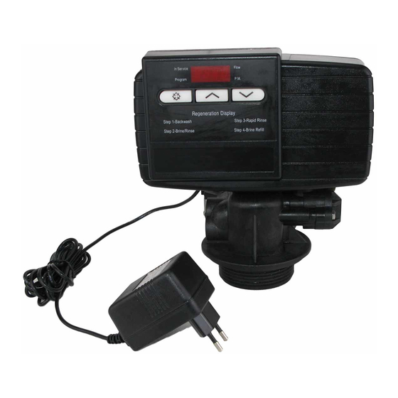
- Page 1 MODEL 5600SE Downflow Brining Service Manual IMPORTANT: Fill in pertinent information on page 2 for future reference.
-
Page 2: Job Specification Sheet
MODEL 5600SE Downflow Job Specification Sheet Job Number ___________________________________ Model Number ________________________________ Water Test ____________________________________ Capacity Of Unit ________________________ Max. _____________ Per Regeneration Mineral Tank Size: Diameter ___________________ Height _____________________ Under Bedding ____________________________ Amount _______________________ Type Of Media ____________________________ Cubic Feet _____________________... - Page 3 MODEL 5600SE Downflow General Residential Installation Check List WATER PRESSURE: A minimum of 25 pounds of water pressure is required for regeneration valve to operate effectively. ELECTRICAL FACILITIES: An uninterrupted alternating current (A/C) supply is required. Please make sure your volt- age supply is compatible with your unit before installation.
- Page 4 MODEL 5600SE Downflow Control Start-up Procedures Whenever the valve is in Service the current time of day can be set, the control programmed, or an extra regeneration initiated at any time. Set Time Of Day Push either the Up or Down Set Button once to adjust Time Of Day Display by one digit.
- Page 5 MODEL 5600SE Downflow Control Start-up Procedures (Cont’d.) Depending on current control programming, option setting displays that are not required to be set will not be viewed. Set Control Programming 1. The first option setting display that appears in the Program Mode is Treated Water Capacity. Using the Set Up or Down Buttons, set the amount of treated water that can flow through the unit before a regeneration is...
- Page 6 MODEL 5600SE Downflow Control Start-up Procedures (Cont’d.) Start An Immediate Extra Cycle When starting an Extra Cycle, you will have one or two options: 1. Press and Release the Extra Cycle Button: With Immediate Regeneration controls the control will go into regeneration cycle immediately.
- Page 7 MODEL 5600SE Downflow Control Start-up Procudures (Cont’d.) Fast Cycle Valve Thru Regeneration A. Once the valve reaches Regen Step #1 let water run to drain for about 5 minutes. Next, manually step the valve through a regeneration cycle checking valve operation in each step: B.
- Page 8 MODEL 5600SE Downflow Control Operation Timeclock Regeneration Valves In normal operation the Time Of Day Display will be viewed at all times. The control will operate normally until the number of days since the last regeneration reaches the Regeneration Day Override setting. Once this occurs, a regeneration cycle will then be initiated at the preset Regeneration Time.
- Page 9 MODEL 5600SE Downflow Water Conditioner Flow Diagrams (Downflow Brining) Using Black Cycle Cam (Part No. 17438) Service Position Backwash Position (Regeneration Cycle Step #1) Page 9 Printed in U.S.A.
- Page 10 MODEL 5600SE Downflow Water Conditioner Flow Diagrams (Downflow Brining) Using Black Cycle Cam (Part No. 17438) (Cont’d.) Brine/Slow Rinse Position (Regeneration Cycle Step #2) Rapid Rinse Position (Regeneration Cycle Step #3) Page 10 Printed in U.S.A.
- Page 11 MODEL 5600SE Downflow Water Conditioner Flow Diagrams (Downflow Brining) Using Black Cycle Cam (Part No. 17438) (Cont’d.) Brine Tank Fill Position (Regeneration Cycle Step #4) Service Position Page 11 Printed in U.S.A.
- Page 12 MODEL 5600SE Downflow Control Valve Assembly Page 12 Printed in U.S.A.
- Page 13 MODEL 5600SE Downflow Control Valve Assembly (Cont’d.) Item No. Quantity Part No. Description *1 ... . 2 ... . . 13255 ....Adapter Clip 2 .
- Page 14 MODEL 5600SE Downflow Valve Powerhead Assembly Page 14 Printed in U.S.A.
- Page 15 MODEL 5600SE Downflow Valve Powerhead Assembly (Cont’d.) Item No. Quantity Part No. Description 1 ... 1 ... 26001-02 ... . . Drive Housing, Black 2 .
- Page 16 MODEL 5600SE Downflow 3″ Turbine Meter Assembly Item No. Quantity Part No. Description 1... . 2... . 13314....Screw, Hex Washer, 8-18 x 5/8 2.
- Page 17 MODEL 5600SE Downflow By-pass Valve Assembly, Plastic Item No. Quantity Part No. Description 1 ... .1 ... . 19723 ....By-Pass Valve Body, Plastic 2 .
- Page 18 MODEL 5600SE Downflow By-pass Valve Assembly, Brass Item No. Quantity Part No. Description 1 ... . 1 ... . 17290....By-Pass Valve Body, 3/4″...
- Page 19 MODEL 5600SE Downflow 2300 Safety Brine Valve Item No. Quantity Part No. Description 1 ... 1 ... 60027-00 ... . . 2300 Safety Brine Valve Body 2 .
- Page 20 MODEL 5600SE Downflow 2310 Safety Brine Valve Page 20 Printed in U.S.A.
- Page 21 MODEL 5600SE Downflow 2310 Safety Brine Valve (Cont’d.) Item No. Quantity Part No. Description 1 ... 1 ... 19645 ....Safety Brine Valve Body 2 .
- Page 22 MODEL 5600SE Downflow Valve Wiring Diagram CB1 - 5600SE Circuit Board VDM - Valve Drive Motor EM - Electronic Flow Meter (Optional) SW1 - Homing Switch SW2 - Step Switch HCAM - Homing Cam DFSCAM - Downflow Step Cam Page 22...
-
Page 23: Service Instructions
MODEL 5600SE Downflow Service Instructions A. TO REPLACE BRINE VALVE, INJECTORS, 12. Plug electrical cord into outlet. AND SCREEN 13. Set time of day and cycle the control valve manually to assure proper function. Make sure 1. Turn off water supply to conditioner: control valve is returned to the service position. - Page 24 MODEL 5600SE Downflow Service Instructions (Cont’d.) 9. Return by-pass or inlet valving to normal service E. TO REPLACE METER position. Water pressure should now be applied 1. Follow Steps A.1 through A.3. to the conditioner, and any by-pass line shut off.
- Page 25 MODEL 5600SE Downflow Service Instructions (Cont’d.) PROBLEM CAUSE CORRECTION Softener fails to regenerate. A. Electrical service to unit has been A. Assure permanent electrical Interrupted. service (check fuse, plug, pull chain or switch). B. Timer is not operating properly. B. Replace timer.
- Page 26 MODEL 5600SE Downflow Service Instructions (Cont’d.) PROBLEM CAUSE CORRECTION Iron in conditioned water. A. Fouled resin bed. A. Check backwash, brine draw and brine tank fill. Increase frequency of regeneration. Increase back- wash time. B. Iron content exceeds recom- B. Add iron removal from filter or mended parameters.
- Page 27 1 ..13446-40 . . . End Plug Assy. - Green 1 ..17218 ..Piston, Downflow Rapid Rinse 60125 ..5600SE Seal and Spacer Kit For Illustration and Parts List, See Pages 12 and 13 5 .
- Page 28 P/N 19742 Rev. 2 9/99 Printed 9/99...