
Related Manuals for Panasonic AG-MX70


Summary of Contents for Panasonic AG-MX70
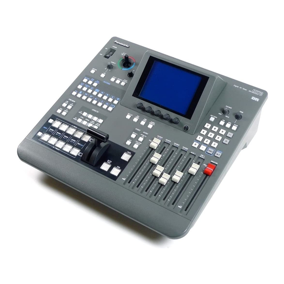
- Page 1 Digital AV Mixer Before attempting to connect, operate or adjust this product, please read these instructions completely.
- Page 2 CAUTION RISK OF ELECTRIC SHOCK DO NOT OPEN CAUTION: TO REDUCE THE RISK OF ELECTRIC SHOCK, DO NOT REMOVE COVER (OR BACK). NO USER SERVICEABLE PARTS INSIDE. REFER TO SERVICING TO QUALIFIED SERVICE PERSONNEL. The lightning flash with arrowhead symbol, within an equilateral triangle, is intended to alert the user to the presence of uninsulated “dangerous voltage”...
-
Page 3: Overview
Overview This digital audio mixer is designed for a host of applications including cases where the video signals of video equipment are combined through digital processing or where many different kinds of effects are added. It incorporates two frame synchronizers, a feature which makes it unnecessary for two video signals to be synchronized. Its dedicated software program, the MX-Navi, enables titles to be downloaded from a PC to facilitate the insertion of titles. -
Page 4: Table Of Contents
Contents AG-MX70 Overview ... 3 Parts and their functions ... 6 Front panel controls ... 6 Rear panel connection area ... 14 External interfaces ... 17 GPI ... 17 RS-422A ... 17 RS-232C ... 17 Tally ... 17 System diagram ... 18 Power supply and backup ... - Page 5 Opening the transmission list ... 89 Deleting Title data from the transmission list ... 89 Other operations ... 90 Checking the memory status of the AG-MX70 ... 90 Changing the AG-MX-70 memory settings ... 90 Transmission and playback of IntVideo data ... 91 Clearing IntVideo data ...
-
Page 6: Parts And Their Functions
Parts and their functions Front panel controls POWER switch This is used to switch the AC power on and off. Select “Power” from the “Setup” initial setting screen: “Reset” is selected to establish the default setting when the power is turned ON, and “Preset” is selected to start operation using the same settings which were in effect upon conclusion of the previous operation. -
Page 7: Mix Button
Parts and their functions REV (reverse) button This button is used to reverse the keys and transition key patterns, reverse the frame in/out, and reverse the chroma key, luminance key, external key and title signals. The button’s lamp flashes with patterns that have no reverse operations, indicating that these patterns cannot be reversed. - Page 8 Parts and their functions 5 7 9 ; EFFECTS PREVIEW PROG PROG STILL STROBE PRESET PRESET 6 8 : < Preview output selection area The controls in this area are used to determine which images among the transition preview, DSK preview and A/B bus images are to be output from the PREVIEW output connector on the rear panel.
- Page 9 Parts and their functions Setting panel area < LCD (liquid crystal) display The effect parameters, time settings and other information are shown on this display. 2 Joystick, Z parameter display area During positioning, the X/Y/Z parameters are displayed here; during the color settings, the Pb/Pr/Y parameters are displayed.
- Page 10 Parts and their functions < A LCD CONTRAST control This control is used to adjust the contrast of the LCD display. M o d i f y B SET UP (initial setting page display) button This button displays the initial setting page. C INT VIDEO (internal video setting page display) button This button displays the internal video setting page.
-
Page 11: Enter Key
Parts and their functions PHONE TIME PATTERN FADE TITLE PLAY INT PLAY CANCEL SHIFT < PHONE (headphone volume) control This control is used to adjust the level of the rear panel headphone (PHONE) output. The sound of the portion to be faded using the DSK/Fade setting can be monitored before fading so that it can be heard even when AudioFade is used. - Page 12 Parts and their functions SOURCE SHIFT 1 / 5 SHIFT key This key has the same function as the shift key for the number keys. 2 A/PROG /SOURCE 1/5 selector button This button is used to select source 1 selected by the initial settings for the A/PROG bus.
-
Page 13: Master Fader
Parts and their functions Audio mixer area SOURCE 1/5 fader This fader is used to adjust the audio level of input 1 which was set on the initial setting page; when it is operated together with the shift key, it is used to adjust the audio level of input 5. -
Page 14: Rear Panel Connection Area
Parts and their functions Rear panel connection area 1 2 3 4 5 6 7 8 9 EXT IN EXT IN (external key input area) External key input connector This connector can be used for key or DSK applications. It can also be used for genlock signal using the settings on the initial setting page. - Page 15 Parts and their functions Composite/component Y input 1 connector 2 Composite 5/component P 3 Component P input 1 connector 4 YC input 1 connector 5 Composite/component Y input 2 connector 6 Composite 6/component P 7 Component P input 2 connector 8 YC input 2 connector Composite output 1 connector 2 Component Y output 1 connector...
- Page 16 Parts and their functions Analog audio 1 input connectors The audio signals supplied to these connectors are input to the cross point selected on the initial setting page. 2 Analog audio 2 input connectors The audio signals supplied to these connectors are input to the cross point selected on the initial setting page.
-
Page 17: External Interfaces
This enables the unit to be controlled using a personal computer. All of the unit’s functions with the exception of AUX 1 and AUX 2 can be set. ≥ Connection of conversion cable RS-232C AG-MX70 25-pin 9-pin 1 TXD 1 SPARE... -
Page 18: System Diagram
Termination Box camera Through connection Box camera Through connection Box camera Termination CPST Y, Pb, Pr ADV-REF (Genlock enabled as AG-MX70 (Video) genlock source) Y, Pb, Pr SDI IN2 (Video) SDI IN3 SDI IN4 (Audio/Video) Microphone PC (with MX-Navi already... - Page 19 (Audio/Video) RS-422A (Audio/Video) REF *1 RS-422A SDI IN1 SDI IN2 SDI IN3 (Audio/Video) SDI IN4 AUX1/AUX2 (Audio/Video) Analog audio signals Editing controller G/L *2 (Genlock enabled as genlock source) Signal generator AG-MX70 SDI OUT PC (with MX-Navi already installed) RS-422A...
-
Page 20: Power Supply And Backup
Power supply and backup The operation panel settings are stored in the memory when the power is turned off. The default settings are established when the power is turned back on by selecting [Power] > [Reset] on the [Setup] initial setting screen, and the system is started from the settings which were established at the completion of the previous session by selecting [Power] >... - Page 21 [INTVideo] internal video setting screen When [Back Matte] has been selected The joystick XY and rotary Z control displays are set to Wash, and the wash color that is the companion color for gradation is set. The joystick [X][Y] and rotary [Z] display change to [Pb], [Pr] and [Y], and the color can be set. [Pb][Pr] can be set to any value from 0 to 255 and [Y] to any value from 16 to 255 but only when [Custom1] or [Custom2] has been selected using rotary 2 control.
- Page 22 [INTVideo] internal video setting screen When [Memory] has been selected Described below are the write and preview procedures for “Still” (still picture) or “Movie” (moving picture). It is possible to set the number of frames (number of pages) that can be used to a maximum of 30 (NTSC) or 26 (PAL). However, if pages are allocated to titles, the number of pages will be reduced by the equivalent amount.
-
Page 23: [Color Effects] Setting Screen
[Color Effects] setting screen Color Pb 128 Pr 128 Effect C Gain 128 Event 10:00 Color Effects Y Setup Y Gain This menu is selected using the A or B bus [Color Effects] button. If the status of the [Color Effects] button is not to be changed, press the [Color Effects] button of the bus to be set while holding down the [Shift] key. -
Page 24: [Video Effects] Setting Screen
[Video Effects] setting screen Pos. X 128 Y 128 Z 128 Event 10:00 Video Effects Mosaic Defocus Mono Time Effects Decay Paint Nega Mirror This menu is selected using the A or B bus [Video Effects] button. If the status of the [Video Effects] button is not to be changed, press the [Video Effects] button of the bus to be set while holding down the [Shift] key. - Page 25 [Video Effects] setting screen [Mosaic] setting Select [On] or [Off] for this effect using the rotary 2 control. The default setting is [Off]. Select [XY] (both horizontal and vertical), [X] (horizontal only) or [Y] (vertical only) using the rotary 3 control. Set the size using the rotary 4 control.
- Page 26 [Video Effects] setting screen [Time Effects] still/strobe setting Select the still or strobe effect with Video Effects ON using the rotary 2 control. ≥ When [Off] has been selected The regular screen is output. ≥ When [Still] has been selected Either [Field] or [Frame] is selected as the type using the rotary 3 control.
- Page 27 [Video Effects] setting screen [Decay] setting The A and B multi strobe, transition, Key, DSK shadow and trail cannot be selected at the same time. Only one of these effects is valid at a time. Select [On] or [Off] for the effect using the rotary 2 control. Any time setting from 0 to 32 can be selected using the rotary 3 control.
- Page 28 [Video Effects] setting screen [3D] setting Select [OFF], [Ripple], [Multi] or [Spark] for 3D using the rotary 2 control. This setting is only effective when the 3D optional board (AG-VE70) has been installed. It cannot be made to take effect at the same time as 3D transition or key pattern.
- Page 29 [Video Effects] setting screen <Notes> ≥ In the case of pattern numbers 200 to 211, 1001 to 1034, 213 to 220, 222, 1060 to 1067 and 1069, transitions can be initiated with the DVE setting parameters applied to the B channel. When this is done, the pattern is changed to MIX (56). (With the A bus/B bus) With the preset bus/program bus, the effects are applied to preset, and they are turned off by setting the reverse button to ON.
-
Page 30: Execution Of Effects
Execution of Effects AB transition 1) Preparation Slide the transition lever to the A side. 2) Input selection and preview Select the input source of the transition destination using the B bus cross point button. The preview selection can now be set as ME and the images of the transition destination can be previewed at the Preview connector. -
Page 31: Effect-By-Effect Setting Screens
Effect-by-effect setting screens The settings for the transition and key patterns are performed on these screens. The items that can be set differ from one pattern to another. The LCD display changes as soon as one of the patterns is selected. The key slice, slope, key level, crop, edge, effects and DVEPlus settings are stored in the memory for each effect group. - Page 32 Effect-by-effect setting screens [Pattern Edge] setting This is used to set edges for the patterns. The border color set here is used as the border matte for trail. It is updated by the color which is read out for the direct pattern. Select [Hard], [Soft], [Border] or [Soft Border] using the rotary 2 control.
- Page 33 Effect-by-effect setting screens [Effects] setting This is used to perform the DVE settings. Select the [Off], [Shadow] or [Trail] effect using the rotary 2 control. Set the [Light] (lighting) using the rotary 5 control. This is valid only when the 3D optional board (AG-VE70) has been installed for use.
-
Page 34: [Chroma Key] Setting
Effect-by-effect setting screens [Chroma Key] setting The chroma key is opened directly or when selected using the number keys. The RGB selected color display can be selected using [Shift] + rotary 2. Alternatively, the number of the selected color can be switched and written over the existing data. - Page 35 Effect-by-effect setting screens [Color cancel] setting This is used to perform the settings for color cancel. The offset from the [Offset] key can be set to any value from 0 to 255 using the rotary 2 control. The [C Slice] (cancel slice) can be set to any value from 0 to 255 using the rotary 3 control.
-
Page 36: [Luminance Key] And[Ext Key] (External Key) Settings
Effect-by-effect setting screens [Luminance Key] and [EXT Key] (external key) settings The luminance key and external key are opened directly or when selected using the number keys. Pos. X 128 Y 128 Z 196 Event ME Time 10:00 Luminance Key Crop Effects Border... -
Page 37: [Title Key] Setting
Effect-by-effect setting screens [Title Key] setting The title key is opened directly or when selected using the number keys. It is not displayed when Page is 0. The number of frames (number of pages) that can be stored in the memory for PC Title can be set on the [Setup] screen. Pos. -
Page 38: [Basic Pattern Key] Setting
Effect-by-effect setting screens [Basic Pattern Key] setting (numbers 3001 to 3046) The basic pattern key is opened directly or when selected using the number keys. Pos. X 128 Y 128 Z 196 Event ME Time 10:00 Basic Pattern Key Pattern Edge Effects Plus... -
Page 39: Other Key Settings
Effect-by-effect setting screens Other key settings (numbers 3301 and up) The pattern keys are opened directly or when selected using the number keys. The size is set using the rotary Z control. With patterns whose positions can be changed, the position can be set using the joystick. - Page 40 Effect-by-effect setting screens [3Dmodify] setting This takes effect only for the special 3D patterns (numbers 6001 to 6438 and 6601 to 6716) when the 3D optional board (AG- VE70) has been installed. The parameters of the pattern for the 3D keys can be changed using the rotary 2, 3, 4 and 5 controls. They can be stored in the memory for each pattern.
- Page 41 Effect-by-effect setting screens ≥ With the page turn group (number 6008) R2: [Rotate] (rotation) setting R3: [Angle] setting R4: [Turn] setting R5: [Radius] setting ≥ With the ripple group (number 6031) R2: [Level] (amplitude) setting R3: [Time] setting R4: [Width] setting The position of the ripple center can be changed using [Shift] + XY.
- Page 42 Effect-by-effect setting screens [Key Learn] setting This is used to set key learn. It cannot be set for number 3001 to 3006, 3301 to 3305, 6001 to 6003 and 6006 to 6010 doors. The key XYZ, key level and 3D modify settings are stored in the memory for each key frame.
- Page 43 Effect-by-effect setting screens Pos. Event Learn Insert Replace CLR KF Copy Paste Exit In the key learn editing mode, the key frame number is displayed in [K Frame]. Using the rotary 1 control, the editing items are selected and key frames are set. Key frames 00 to 19 can be set, and they are displayed during editing in the rotary 2 control display area.
- Page 44 Effect-by-effect setting screens With flag (#6002) Insert Flag Replace CLR KF K Frame Copy Paste Width Angle Time Exit R2: [Width] (flag width) setting R3: [Angle] setting R4: [Time] (fluttering time) setting R5: [Amp] (amplitude) setting 3D parameters are the same as with 3DModify. With accordion (#6003) Insert Accordion...
- Page 45 Effect-by-effect setting screens <Notes> When a compression effect has been applied to images, some of the effects may be automatically canceled. ≥ When applying 2D compression effects to channel A Under the conditions below, the Still, Strobe and Multi Strobe for channel A are turned OFF when the Transition lever or key size adjustment Z has been changed or the compression rate has been changed by the aspect ratio.
-
Page 46: Dsk/Fade Settings
DSK/Fade settings These settings are opened when the DSK/FADE button or DSK Preview is selected. Both DSK and Fade settings can be performed. Select the [DSK Source], [DSK Key], [Crop], [DSK On/Off], [DSK Effects] or [Fade] item using the rotary 1 control. When the title memory is 0, the Key [Memory], Source [Memory], [Memory], [Mode] and [Slide] settings are canceled. -
Page 47: [Dsk Key] Settings
DSK/Fade settings [DSK Key] settings These are used to set the DSK key signals (for external applications). Memory keys are used in their original form. The [Slice] level can be set to any value from 0 to 255 using the rotary 2 control. The default setting is 0. [Slope] can be set to any value from 0 to 15 using the rotary 3 control. -
Page 48: [Fade] Settings
DSK/Fade settings [Fade] settings These are used to perform the fade settings. The image to be faded is selected from [Black], [White] or [Blue] using the rotary 2 control. The default setting is [Black]. [On] or [Off] is selected for [Audio] fading using the rotary 3 control. -
Page 49: [Audio Effects] Settings
[Audio Effects] settings 1 - 8 Aux1 Aux2 [Audio Effects] is opened using Audio Effects or the ON button. Audio effects can be set for each input. Select the input from [1] (crosspoint 1), [2] (crosspoint 2), [3] (crosspoint 3), [4] (crosspoint 4), [5] (crosspoint 5), [6] (crosspoint 6), [7] (crosspoint 7), [8] (crosspoint 8), [AUX1] or [AUX2] using the rotary 1 control. -
Page 50: [Eq] Equalizer Setting
[Audio Effects] settings [EQ] equalizer setting This is used to set the equalizers. Set [On] or [Off] for all equalizers using the rotary 3 control. The default setting is [On]. The [L Level] bass level can be set in 2 dB intervals to any value from –14 dB to 0 to +14 dB using the rotary 5 control. -
Page 51: [Setup] Initial Setting Screen
[Setup] initial setting screen Wash Ph 128 Pr 128 Z 196 Event 10:00 Setup Power Direct Pattern Audio Input Video Memory INT V Lock Video Format System1 1Frame System2 Type Audio Alignment Level File Empty Select the item to be set using the rotary 1 control. Items consist of [Power], [Direct Pattern], [Audio Video], [Memory], [Gen Lock], [Video Format], [System1], [System2], [Bus], [Audio Level] and [File]. -
Page 52: [Power] (Power On) Setting
[Setup] initial setting screen [Power] (power ON) setting Whether the system is to be started from the [Reset] status, from the [Preset] status or in the [Demo] mode can be selected using the rotary 2 control. With [Reset], the settings except for the event memories, setup settings, file memory and key learn settings are initialized. - Page 53 [Setup] initial setting screen The LCD display now shows the setting screens for each effect pattern. Proceed to set the edges and effects, and if the settings are acceptable, enter them using [Enter], and return to the direct pattern settings. Example of transition Pos.
-
Page 54: [Audio Video Input] Settings
[Setup] initial setting screen [Audio Video Input] settings These are used to set the audio and video inputs. When [Setup] is selected using the rotary 2 control and [Enter] is pressed, [OK?] appears so press [Enter] to change to the setting mode. Use [Shift] + [Enter] to cancel. When [Default] is selected using the rotary 2 control and [Enter] is pressed, [OK?] appears so press [Enter] to change to the default setting. -
Page 55: [Memory] Setting
[Setup] initial setting screen [Memory] setting This is used to set the memories used for INTVideo and DSK. When the setting is changed, all the memories are cleared. How much memory is to be used for [INT V] and how much for [Title] for DSK and TitleKey is set using the rotary 2 and 3 controls. -
Page 56: [System1] Setting
[Setup] initial setting screen [System1] setting This is used to perform a variety of settings. The rotary 2 control is used to set the amount of delay for the source input when the [AdvRef] advanced reference signal is connected with the 3D optional board (AG-VE70) installed. -
Page 57: [Audio Level] Setting
[Setup] initial setting screen [Audio Level] setting The [Alignment] (alignment) level is set using the rotary 2 control. [–3 dB], [0 dB] or [4 dB] can be selected. The default setting is [4 dB] for NTSC and [0 dB] for PAL. The [Head] (headroom) is set using the rotary 5 control. -
Page 58: Other Settings
Other settings Event memory Setting method One hundred panel statuses can be stored in event memories 0 to 99. Press the Set button, set the event number using the number keys, and enter the setting using [Enter]. Set button: Its lamp lights during the setting process. When [Enter] is pressed, it flashes for two seconds and then goes off. -
Page 59: Transition Time Setting
Other settings Transition time setting Select the item to be set, and press the [ME], [DSK] or ME Time [FADE] button. 10:00 Input the numerical value using the number keys, and press [Enter]. The numerical value can be incremented and decremented PHONE using rotary TIME or the “+”... -
Page 60: Transition Patterns
Transition patterns Basic Pair Blinds Multi H3 Multi V3 Multi H6 Overlap Multi V6 Multi HV3 Multi HV6 Multi PairH3 Overlap Multi PairV3 Overlap... - Page 61 Transition patterns Basic Pair Blinds Multi H3 Multi V3 Multi H6 Multi V6 Multi HV3 Multi HV6 Overlap Multi PairH3 Multi PairV3 Overlap...
- Page 62 Transition patterns Multi PairH6 Multi PairV6 Multi PairHV3 Multi PairHV6 Mtrix Overlap Basic2 Overlap Mosaic Mosaic Mosaic BPreset Overlap 1001 1002 1003 Shutter STILL STILL STILL Overlap 1091 1092 1093 Direct DT 1 DT 2 DT 3 Pattern Comp1 Overlap 1501 1502 1503...
- Page 63 Transition patterns Multi PairH6 Multi PairV6 Multi HV3 Multi PairHV6 Panel Panel Panel Setting Setting Basic2 Still Still BPreset Field Fram 1059 1060 1061 M I X 1010 Direct DK 1 DK 2 DK 3 Pattern Comp1 Overlap 1511 1512 1531 1532 +Diss...
- Page 64 Transition patterns Slide1 Overlap 1301 1302 1303 +Diss 1311 1312 1313 Slide2 Overlap 1341 1342 1343 2D Move1 Overlap 1401 1402 1403 +Diss 1411 1412 1413 2D Move2 /Exp Overlap 1421 1422 1423 +Diss 1431 1432 1433 2D Move2 /Exp Curve2 Overlap 1461...
- Page 65 Transition patterns Bounce Overlap 1321 1323 +Diss 1331 1332 1333 2D Move2 /Exp Overlap 1441 1442 1443 +Diss 1451 1452 1453 2D Move2 /Exp Curve2 Overlap 1481 1482 1483 +Diss 1491 1492 1493 Split Slide 2DComp 1631 1632 1633 +Diss 1671 1672 1673...
- Page 66 Transition patterns Spin 1841 1842 1843 +Diss 1851 1852 1853 Flip Tumble Overlap 1902 1903 1904 Twist 2001 2002 2003 +Diss 2011 2012 2013 Roll 2051 2052 2053 +Diss 2071 2072 2073 Page1 2101 2102 2103 +Diss 2151 2152 2153 Page2 2118 2119...
- Page 67 Transition patterns Spin 2DComp 1861 1862 1863 +Diss 1871 1872 1873 Flip Tumble Overlap 1964 1965 1966 Shutter Overlap 1971 1972 1973 Roll 2059 2060 2061 +Diss 2079 2080 2081 Page1 2109 2110 2111 +Diss 2159 2160 2161 Page2 2126 2127 2128 +Diss...
-
Page 68: Key Patterns
Key patterns BasicPattern 3001 3002 3003 Diss 3021 3022 3023 3041 3042 3043 Exp+Diss Basic Key 3101 3102 3103 Overlap PinP 3301 3302 3303 Diss 3311 3312 3313 3321 3322 3323 Exp+Diss 2D Move 3401 3402 3403 +Diss 3411 3412 3413 2D Move2 ExpCurve2... - Page 69 Key patterns Spot Light Back Back Diss 3305 3315 Exp+Diss 3325 2D Move 3421 3422 3423 +Diss 3431 3432 3433 2D Move2 ExpCurve2 3461 3462 3463 +Diss 3471 3472 3473 DualPinP Move 3521 3522 3523 +Diss 3531 3532 3533 DualPinP Move 3561 3562...
- Page 70 Key patterns Pers1 2DComp 4701 4702 4703 +Diss 4741 4742 4743 PersMove1 2DComp 4761 4762 4763 +Diss 4781 4782 4783 PersMove2 2DComp 4801 4802 4803 +Diss 4821 4822 4823 Spin 2DComp 4841 4842 4843 +Diss 4851 4852 4853 Sphere 2DComp 5201 5202 5203...
- Page 71 Key patterns Pers1 2DComp 4734 4735 4736 +Diss 4754 4755 4756 PersMove1 2DComp 4769 4770 4771 +Diss 4789 4790 4791 Spin 2DComp 4861 4862 4863 +Diss 4871 4872 4873 Sphere 2DComp 5210 5211 5212 +Diss 5240 5241 5242 Flag1 2DComp 5413 5414 5415...
- Page 72 Key patterns Accordion Move 6201 6202 6203 +Diss 6211 6212 6213 Sphere Move 6301 6302 6303 +Diss 6311 6312 6313 Sphere Curve Move 6401 6402 6403 +Diss 6411 6412 6413 Spin to Pers Move 6501 6502 6503 +Diss 6521 6522 6523 Pers In Move...
- Page 73 Key patterns Accordion Move 6221 6222 6223 +Diss 6231 6232 6233 Sphere Move 6321 6322 6323 +Diss 6331 6332 6333 Sphere Curve Move 6421 6422 6423 +Diss 6431 6432 6433 Pers In Move 6621 6622 6623 +Diss 6631 6632 6633 Title Learn11 Learn12...
-
Page 74: Mx-Navi
≥ DSK display of the PC screen as telop or animation. ≥ Display of the PC screen with internal matte. ≥ Images provided as input to the AG-MX70 can be read into the PC as still images and be converted to image files. System requirements The PC to be used should meet the following requirements. -
Page 75: Processing Of Image Data
Image data is processed by the AG-MX70 either as Title data or IntVideo data, depending on the application. When image data is transmitted to the AG-MX70, it is necessary to first select one of these 2 data types. ≥ Title data Data to be used for DSK playback should be transmitted as Title data. -
Page 76: Management Of The Image Memory
∫ Management of the image memory ≥ Memory capacity Images transmitted from the PC are stored in the AG-MX70’s image memory. The memory capacity differs, depending on the AG-MX70’s video format setting. NTSC: 30 pages (1 page = amount of memory required for 1... -
Page 77: Before Use
Before use AG-MX70 connections It is necessary to connect the PC to the AG-MX70 using the USB cable before installing the software. Follow the steps below. 1) Turn off the power to the AG-MX70. 2) Connect the PC to the AG-MX70 using the USB cable. -
Page 78: For Windows Me
Before use ∫ For Windows ME 1) Connect the PC to the AG-MX70 correctly. 2) Turn on the power to the PC. Check that Windows has started up. 3) Place the setup CD-ROM in the PC’s CD-ROM drive. 4) Turn on the power to the AG-MX70. -
Page 79: Installation Of Mx-Navi
This completes installation of all of the software. Use the following procedure to confirm that the software has been installed correctly. 1) Confirm that the PC and the AG-MX70 have been connected correctly and that the power of the AG- MX70 is switched on. -
Page 80: Startup And Shutdown
Startup and shutdown How to start up MX-Navi Select “Program” > “Panasonic AG-MX70” > “MX-Navi” from the Windows Start menu. How to shut down MX-Navi Shutdown is possible in the following two ways. ≥ Click the button at the right top of the main window. - Page 81 Screen descriptions D, F The upper line shows the Divide value for the data and the lower line shows the number of images of the data. ICON The image is reduced and displayed. When several files are used with one title, one of them will be used for the display.
-
Page 82: List Mode
Screen descriptions List mode For data with a Mark setting, the Mark number is displayed. This is displayed for data with the Protect setting. O (Order) The order of the data in the transmission list is displayed. This is the same as with icon mode. The Divide value of the data is shown. -
Page 83: Menu Descriptions
Read flash memory This reads the data (SETUP menu settings, operation panel settings, etc.) in the flash memory of the AG-MX70, and saves it in files. Select this menu item after turning on the power while holding down the “0”... -
Page 84: View Menu
Menu descriptions Delete This deletes the selected title from the transmission list. The same operation can be performed with the “DEL” key or by right-clicking on the title data display column and selecting “Delete” from the pop-up menu. Select all This selects all titles in the transmission list. -
Page 85: Operation Menu
Tool menu Memory status This displays the memory status screen. For details, refer to “Checking the memory status of the AG-MX70” (page 90). AG-MX70 setup This displays the memory setting screen. For details, refer to “Changing the AG-MX-70 memory settings” (page 90) and “Recalling events”... -
Page 86: Title Data Operations
The procedure for transmission of PC images as Title data and DSK playback is as follows. 1) Register the image in the list of Title data for transmission to the AG-MX70 (transmission list). 2) Perform data playback settings. 3) Play... - Page 87 Title data operations Description of the setting items (depending on the data playback format, some items may not be displayed or setting may not be possible) Icon: This is used for setting the frame number of the image to be used for display in the ICON row of the main window.
-
Page 88: Manual Transmission And Playback Of Title Data
In order to perform DSK playback for the data, it is necessary to set Key and Fill to Title using the DSK/Fade item on the DSK Fade menu of the AG-MX70. For details, refer to page 46. Automatic transmission and playback of Title... -
Page 89: Checking The Title Data Image
Title data operations Checking the Title data image The image of the data selected on the image display screen can be displayed in the original size so it can be checked. The image display screen can be displayed using one of the following methods. -
Page 90: Other Operations
Other operations Checking the memory status of the AG-MX70 The status of the image memory of the AG-MX70 can be checked on the memory status screen. Select “Tools” > “Memory status” from the menu of the main window to open the memory status screen. -
Page 91: Transmission And Playback Of Intvideo Data
Saving data Title data or IntVideo data can be read to the PC from the image memory of the AG-MX70 and can be stored as still images. Use the following procedure. 1) Select “Tools” > “Memory status” from the menu of the main window to open the memory status screen. -
Page 92: Setting The Initial Properties
Other operations Setting the initial properties The initial values for the properties to be used with new data can be set on the “Initial set of Property Data” setting screen. 1) Select “Initial set of Property Data” from the Tools menu of the main window. The “Initial set of Property Data”... -
Page 93: Setting The Operating Environment
When this is checked, the confirmation screen will be displayed when the application is shut down. Memory management The operation when the AG-MX70 is connected to the PC is set. When “Memory clear when re-connect” is checked, all Title and IntVideo data will be cleared when the AG- MX70 is connected. -
Page 94: List Of Short-Cut Keys
List of short-cut keys Move the cursor to the top Move the cursor back by 10 Move the cursor back Move the cursor ahead Move the cursor ahead by 10 Move the cursor to the bottom Jump to the data in DSK Jump to the data of the corresponding Mark setting Open the properties of the selected data Transfer the selected data... -
Page 95: Before Calling For Service
Please check Power and connection, and try again..” is displayed. ≥ The image does not Check that the DSK/Fade items Key and Fill in the DSK/Fade menu of the AG-MX70 are set to Title. change to DSK even when playback operation is performed. - Page 96 Before calling for service MX-Navi-related problems Problem ≥ Patterns set for DSK ON When the set pattern can not be used for DSK, the pattern is changed automatically to a different pattern. and DSK OFF for Title data are changed. When Protect has been set for the data, it will not be cleared even when clearing is performed ≥...
-
Page 97: Specifications
Specifications [GENERAL] Power Source : 120 V AC, 50/60 Hz Power Consumption : 52 W (with no optional accessories installed), 70 W (with all optional accessories installed) indicates safety information. Operating temperature: Operating humidity: Dimensions (W k H k D): Weight: [VIDEO] Video format:... - Page 98 M6 a 1, –60 dBv, 2 kh, unbalanced (switchable with AUX2) M6 a 1, 8 kh, unbalanced D-sub 9-pin, RS-422A/232C switchable RS-422A protocol; GVG/Sony switchable Panasonic: AG-A850, AJ-A900, SONY: BVE-2000, BVE-910, PVE-500 D-sub 9-pin, open-collector k 8 ch Collector current: Less than 50 mA,...
- Page 99 Specifications [SDI] (Option) Video input connectors: Video output connectors: Audio input connectors: Audio output connectors: [ACCESSORIES] Power cable ...1 Operating Instructions...1 MX-Navi installation CD...1 Warranty card ...1 BNC a 4 (inputs 1/2/3/4), SMPTE 259M-C/EBU Tech.3267-E BNC a 1, SMPTE 259M-C/EBU Tech.3267-E Embedded audio (channels 1/2, 3/4, 5/6, 7/8 switchable) Embedded audio (channels 1/2)
- Page 100 Installation of the AG-YA70 The AG-YA70 is an interface board that enables the AG-MX70 to be connected to a serial digital interface (SDI). Follow the procedure below to install it. <Note> Always consult your dealer or authorized service center regarding installation of the AG-YA70 in the AG-MX70.
-
Page 101: Installation Of The Ag-Ve70
Installation of the AG-VE70 The AG-VE70 is a 3D effect board that enables the 3D patterns, etc. of the AG-MX70 to be used. Follow the procedure below to install it. <Note> Always consult your dealer or authorized service center regarding installation of the AG-VE70 in the AG-MX70. - Page 102 PANASONIC BROADCAST & TELEVISION SYSTEMS COMPANY UNIT COMPANY OF MATSUSHITA ELECTRIC CORPORATION OF AMERICA Executive Office: One Panasonic Way 4E-7, Secaucus, NJ 07094 (201) 348-7000 EASTERN ZONE: One Panasonic Way 4E-7, Secaucus, NJ 07094 (201) 348-7621 Southeast Region: 1225 Northbrook Parkway, Ste 1-160, Suwanee, GA 30024 (770) 338-6835...