Panasonic WR-DA7 Service Manual
Panasonic wr-da7 audio mixer service manual
Hide thumbs
Also See for WR-DA7:
- User manual (369 pages) ,
- Application manual (63 pages) ,
- User manual (425 pages)
Table of Contents
Advertisement
SPECIFICATIONS
General
Power requirement :
Power consumption :
Frequency response :
T.H.D. (total harmonic distortion) :
Equivalent input noise :
Residual noise :
Maximum voltage gain :
Common Mode Rejection Ratio :
Crosstalk :
Dynamic Range (Fs = 48kHz, DIN audio filter) :
AD Converter :
DA Converter :
Internal signal processing :
Sampling Frequency (Fs) :
Signal delay :
The Meter Bridge shown in photo is one of the optional accessories.
AC 120 V 60 Hz
105 W (with options)
20 Hz - 20 kHz, +1 dB - –2 dB
Less than 0.1 % (input = +10 dB/1 kHz, output = +4 dB/RL 600 Ω)
–128 dB (Rs = 150 Ω Input sensitivity = –60 dB typical)
–93 dB typical
84 dB: MIC/LINE(1-16) in to BUS out
84 dB: MIC/LINE(1-16) in to MASTER out
84 dB: MIC/LINE(1-16) in to AUX out
More than 80 dB (1kHz)
90 dB typical (1kHz)
113 dB typical : DA converter (digital in to analog out)
112 dB typical : AD converter (analog in to digital out)
110 dB typical : AD + DA (analog in to analog out)
24 bit, 64 times oversampling (input 1 to 16)
20 bit, 64 times oversampling (aux returns 3 to 6)
24 bit, 64 times oversampling (MASTER, MONITOR A)
24 bit, 128 times oversampling (MONITOR B)
20 bit, 128 times oversampling (aux returns 3 to 6)
32 bit (Dynamic range 192 dB)
Internal: 44.1 kHz and 48 kHz
External: 44.1 kHz ± 6 % and 48 kHz ± 6 %
Less than 2.5 ms, MIC/LINE input to MASTER out
R
WR-DA7
C 1 9 9 8 M a t s u s h i t a C o m m u n i c a t i o n I n d u s t r i a l C o . , L t d .
A l l r i g h t s r e s e r v e d . U n a u t h o r i z e d c o p y i n g a n d
d i s t r i b u t i o n i s a v i o l a t i o n o f l a w .
ORDER NO. AVS9805093C1
D29
Audio Mixer
Advertisement
Table of Contents

Related Manuals for Panasonic WR-DA7


Summary of Contents for Panasonic WR-DA7
-
Page 1: Audio Mixer
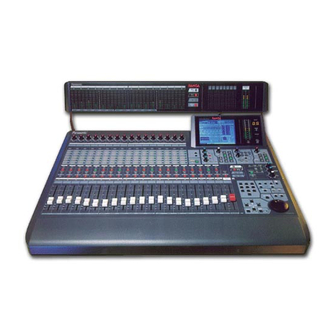
ORDER NO. AVS9805093C1 Audio Mixer WR-DA7 The Meter Bridge shown in photo is one of the optional accessories. SPECIFICATIONS General Power requirement : AC 120 V 60 Hz Power consumption : 105 W (with options) Frequency response : 20 Hz - 20 kHz, +1 dB - –2 dB Less than 0.1 % (input = +10 dB/1 kHz, output = +4 dB/RL 600 Ω) - Page 2 WARNING This service information is designed for experienced repair technicians only and is not designed for use by the general public. It does not contain warnings or cautions to advise non-technical individuals of potential dangers in attempting to service a product. Products powered by electricity should be serviced or repaired only by experienced professional technicians.
- Page 3 Delay : 0 - 14,400 samples/0 - 300 ms (Fs = 48 kHz), 0 - 326 ms (Fs = 44.1 kHz) Phase : normal/reverse (switchable) Stereo meter : Bar graph type LED, Left and Right, 20 points for each VU or PPM (selectable), Peak hold on/off, ∞ Fader : 100 mm motor fader ( x 21), +10 db - –90 dB –∞...
-
Page 4: Optional Accessories
AUX SEND 1/2 : In/Out : Format : IEC 958 Consumer (S/PDIF) 0.5 V [pp]/75 Ω Level : Connector : RCA pin jack WORD CLOCK IN : In/Out : Level : TTL/75Ω switchable Connector : WORD CLOCK OUT/THROUGH : In/Out : TTL/75 Ω, Pass-through (75 Ω... - Page 5 WR-ADDA (A-D/D-A Card (8 in / 8 out)) Input 1 - 8 (balanced) Indicated impedance : 10kΩ Nominal source impedance : 50Ω ~ 600Ω Nominal input level : +4dB (1.23V) Maximum input level before clipping : +18dB (6.15V) Connector type : D-sub 25P Output 1 - 8 (balanced) Indicated impedance :...
-
Page 6: Safety Precautions
PRODUCT COMPLIES WITH DHHS RULES 21 CFR SUBCHAPTER J APPLICABLE AT DATE OF MANUFACTURE SAFETY PRECAUTIONS LEAKAGE CURRENT HOT CHECK GENERAL GUIDELINE 1. Plug the AC cord directly into adaptor socket and plug 1. When service is required, observe the original lead dress. adaptor into the AC outlet. -
Page 7: Table Of Contents
WR-MTBR ................................61 WR-TNDM ................................62 WR-TDIF................................... 65 WR-SMPT................................. 66 WR-AESS ................................. 69 WR-ADAT ................................. 70 Exploded View WR-DA7..................................72 WR-MTBR ................................73 WR-TNDM ................................74 WR-TDIF................................... 75 WR-SMPT................................. 76 WR-AESS ................................. 77 WR-ADAT ................................. 78 Replacement Parts List ............................. 79... -
Page 8: Major Operating Controls And Their Functions
MAJOR OPERATING CONTROLS AND THEIR FUNCTIONS Illustrated Guide AUX section – controls for routing channels to outboard sources and for defining the signal path as either pre- fader or post-fader. Digital Mixer WR - DA7 MEMORY MIC/LINE Display Bridge – contains the LCD screen, L/R meter CONSOLE LOCK display, and primary mixer display status indicators. - Page 9 For more detail, see Chapter 5, Channel, Library, and Channel Fader Strip Meter Windows in the Users' Guide. The ON LED button toggles on ( red ) and off. When on, the MIC/LINE INPUT knob channel output is active. There are two channel numbers for each strip, indicating the INPUT connections on the Rear Panel of the DA7 .
-
Page 10: Equalizer Section
Pan, bus assignment, and surround sound parameters for EQUALIZER Section the selected channel is set within this area. The pan control EQUALIZER is always active for the L/R bus, so you do not need to activate the ON button to pan across the Master L/R out. Q (quality) parameter knob or left surround However, if you wish to pan between odd/even buses, you... -
Page 11: Display Bridge
See Chapter 8 in the Users' Guide for more information on With a channel selected, press an AUX 1-6 LED button surround sound. (green) to select which aux route you wish to assign for the channel. The LEVEL knob performs two functions. By Pressing the bottom knob displays the [DYNAMICS] window pressing the knob, you will assign the channel to the group on the LCD screen. - Page 12 MASTER L/R Fader Strip BUS Fader Strip SOLO LED button SELECT LED button FLIP LED button ON LED button SELECT LED button Bus Assign ON LED button numbers Fader AUX/BUS Layer function Fader AUX/BUS Layer function MASTER L/R Fader Strip BUS Fader Strip The MASTER L/R Fader Strip controls the DA7 master L/R output.
-
Page 13: Monitor Section
INPUT 17-32, when selected (red) , resets the fader strips to AUX routes the AUX SEND outputs to the monitors. control channel inputs 17 through 32, and buses 2, 4, 6, and Press the AUX LED button to monitor the selections, 8. -
Page 14: Library Section
UTILITY Button SCENE MEMORY Section Pressing the UTILITY button will display the [UTILITY] window group on the LCD screen in the Display Bridge. WRITE LED button READ LED button The window displayed will be determined by the window selection buttons at the bottom of the window. Pressing the SCENE MEMORY Section UTILITY button again will cycle the window selections: [OSC_BATT], [CONFIGuration], [USER CuSToM]. - Page 15 The RECALL button opens the library window for the selected function. What this means is that if the [CHANNEL] UNDO/REDO button ARROW buttons window was displayed when you pressed the RECALL button, the CHANNEL library will be displayed. The same MMC/CURSOR button goes for the EQUALIZER AND DYNAMICS/DELAY libraries.
-
Page 16: Lcd Screen
LCD Screen Taskbar Function area Window selection buttons Sample Window Display (CHANNEL window displayed) The LCD screen is the 320x240 backlit liquid-crystal display (LCD) element of the Display Bridge. The screen displays the various windows that show the functions and status of the DA7 . The windows contain areas and items that can be accessed with the cursor control or JogDial. - Page 17 Function Area The two-digit numeric readout displays the most recently accessed SCENE MEMORY. Whenever an AUX monitoring The [function] area of a window contains the various selection button is activated for either MONITOR A or controls, buttons, settings, and values for the current MONITOR B, the numeric display will momentarily display window.
-
Page 18: Rear Panel
Rear Panel Row 2 contains analog INS 1-16 (inserts) with (TRS) phone Everything that goes in, out, and through the DA7 happens plug connectors. Row 3 contains outputs for MASTER OUT, on the Rear Panel, with the exception of the headphone connector. - Page 19 INSERTS 1-16 [REC OUT] Record Output These inserts are used for creating an effects loop. A 1/4” Use 1/4” TRS phone plugs, at a level of +4dB, 10k BAL, to TRS phone plug, with a level of +4 dB, 10k UNBAL, output signals for recording.
- Page 20 AUX SEND 1/2 Clock Input Use RCA connectors to attach a digital effects device or This is used to synchronize the DA7 to an external word another S/PDIF device to the AUX SEND 1/2 and AUX clock source. This allows the DA7 ’s internal clock to slave to RETURN 1/2 digital terminals.
- Page 21 Option Card Slots Slot 1 Slot 2 SMPTE/V SYNC Slot 3 card slot Option Card Slots There are three slots for the optional audio Input/Output cards, plus one dedicated slot for the SMPTE/V SYNC card. The space for the SMPTE/V SYNC card is located directly under the MASTER OUT XLR connectors.
- Page 22 RS232C/485 Connector as shown in fig. 1-5. 1. Test Equipment Required The following Test Jigs are required for Self Check and Service of the WR-DA7. Fig. 1-5 MTBR RTN (Part Number : YWA0EA1203AN) for the AD EXTD-1 (Part Number : YWA0EA1196AN) between Meter Bridge Connector as shown in fig.
- Page 23 2. Disassembling Procedure Referring to Fig. 2-1, remove three knobs and fifteen screws that secure the Upper Cover Ass'y. Remove one screw. Remove eight screws. HA Block Remove three knobs. Upper Cover Ass'y Remove eight screws. Fig. 2-3 Referring to Fig. 2-4, disconnect three Cables from the Remove seven screws.
- Page 24 Self Check Function has been Execution. executed and the Diagnostic Menu 1 as shown in Fig. 3-1 is displayed on the LCD Display of the WR-DA7. 5.3. CPU Test (CPU TEST) Referring to Fig. 3-1, select the CPU TEST Item by either DIAGNOSTICS T.C.
- Page 25 < > For examples DIAGNOSTICS T.C. SEL CH DIAG2 In case of Fig. 5-2, defective IC501 or defective SCENE connection between IC501 and IC518. IC NO MLT/MIX TEST 5.7. DSP Meter Signal Test (METER SIGNAL MLT/MIX/DSP TEST TEST) Move the Cursor to most bottom position by either UP or 513 524 514 523 DOWN Cursor Key.
- Page 26 5.9. Digital Interface Test (DIGITAL I/F TEST) 5.12. Switch LED Test (SW&LED TEST) Move the Cursor to most bottom position by either UP or Referring to Fig. 5-4, select the SW&LED TEST Item by DOWN Cursor Key. either UP or DOWN Cursor. Select the Diagnostic Item (DIAG4) by either LEFT or Execute the SW&LED TEST Item by pressing the Enter RIGHT Cursor Key.
- Page 27 When executing, all contents of the Memories such as the DIAGNOSTICS T.C. SEL CH Current, Scene, Library, Automation and. etc. have been DIAG5 SCENE cleared and return to the initial contents which set in the KNOB TEST PAN/ASSIGN DYNAMICS factory. RIGHT RIGHT RIGHT...
- Page 28 6. Quit of the Self Check Function Move the Cursor to most bottom position by either UP or DOWN Cursor Key. Select the EXIT Item by either LEFT or RIGHT Cursor Key as shown Fig. 6-1. DIAGNOSTICS T.C. SEL CH EXIT SCENE FADER CALIBRATION TEST...
-
Page 29: Wiring Diagram
WIRING DIAGRAM HA BOARD CN56 CN57 CN58 CN59 CN60 CN61 CN62 CN63 YWRDA7L56 (E56-E63) x 8 CN56 CN57 CN58 CN59 CN60 CN61 CN62 CN63 WR-SMPT INS BOARD (OPTION) CN54 CN55 CN98 FUSE YWRDA7L54 (E54) YWRDA7L55 (E55) CN51 POWER-1 BOARD YW30CKIT13W CN54 CN55 CN53... - Page 30 OVERALL BLOCK DIAGRAM MAIN BOARD HA BOARD INS BOARD WR-SMPT (OPTION) PHANTOM SW /PNTM1 /PNTM1-8 /PNTM1~8 MD0-7 MD0-7 MD0-7 SMPTE CONVERTER CONVERTER +50V IC16 IC14 IC11 INS1 IC501-IC513 IC520 +4dB IC518,IC519 WCVSYNC VSYNC SYNC IC523-IC525 IN0102 (+34 - –14dB) (+6dB) (+24 - +2dB) IN0304 IC527 -60 –...
-
Page 31: Main Board (Cpu Section)
BLOCK DIAGRAM OF MAIN BOARD (CPU SECTION) MAIN BOARD CN32 GINV GINV VINV VINV IC20 BUFFER DSPOFF IC21 IC22 SERIAL I/O BUFFER CN44 LBCK TXDATA MTTXD CN36 RXDATA MTRXD LDATA #DFAIL Q3, Q4 LADD +14.5V +14.5V TXCLK LWCK –14.5V –14.5V BACK UP POWER RXCLK CTXD... -
Page 32: Main Board (Panel Control Cpu Section)
BLOCK DIAGRAM OF MAIN BOARD (PANEL CONTROL CPU SECTION) MAIN BOARD IC300 MICROPROCESSOR L.P.F. L.P.F. SCIMS RXD0 L.P.F. SCISM TXD0 L.P.F. SCICK SCK0 OPWDT /WDTOVF L.P.F. /FSYC1 IRQ2 L.P.F. BLANK /FSYC2 SCAN0 Fader Drive Board /RES /RES SCAN1 ... CN1 SCAN2 /PFAIL /NMI... - Page 33 BLOCK DIAGRAM OF MAIN BOARD (DSP SECTION - 1) MAIN BOARD IC518 IC501 IC505 IC509 DSP#18 DSP#1 DSP#5 DSP#9 IC520 AUDIO MUX EMPTY EMPTY EMPTY EMPTY CLKIN CLKIN CLKIN AD0102 DPCLK0 CLKIN DPCLK1 LGR0 DPCLK1 LGR1 DPCLK1 AD0304 /BCKB ARBC1 /BCKC ARBC1 /BCKC...
-
Page 34: Main Board (Dsp Section-2)
BLOCK DIAGRAM OF MAIN BOARD (DSP SECTION-2) MAIN BOARD IC548 SELECTOR MD0-MD15 MD0-MD15 MD0-MD15 MXO1 MA1-MA13 S3DO2 MA1-MA13 MA1-MA13 MXO2 CMA1 LROUT CMA1 DCINA BUSOUT DCINB IC514 IC544 IC523 IC524 IC525 SEL1 DSP#14 LATCH MIX#1 MIX#2 MIX#3 IC516 DDP9A EMPTY DP9A DSP#16 DDP9B... -
Page 35: Main Board (Audio Interface Section)
BLOCK DIAGRAM OF MAIN BOARD (AUDIO INTERFACE SECTION) MAIN BOARD PNTM1 SLOT I/F IC410 PNTM2 IC410 IC402 PNTM3 BUFFER CN37 IC410 CN33 PNTM4 /SLTWR SLT256 SLT256 IC410 /PNTM1 /MWRCK PNTM5 SLT64 SLT64 /PNTM2 IC410 /CSSL1 PNTM6 /SLCS1 SLTFS SLTFS /PNTM3 IC410 /CSSEL2 /SLCS2... -
Page 36: Ad/Da Board (1/2)
BLOCK DIAGRAM OF AD/DA BOARD (1/2) AD/DA BOARD CN33 /PNTM1 /PNTM1 /PNTM2 /PNTM2 /PNTM3 /PNTM3 /PNTM4 /PNTM4 AD CONVERTER CH1/2 /PNTM5 /PNTM5 CN54 VCOM /PNTM6 /PNTM6 /PNTM7 /PNTM7 AINL+ IC2A /PNTM1 /PNTM1 /PNTM8 /PNTM8 SDAT IN0102 IN0304 /PNTM2 /PNTM2 IC1A IN0506 AINL–... -
Page 37: Ad/Da Board (2/2)
BLOCK DIAGRAM OF AD/DA BOARD (2/2) AD/DA BOARD IC501 (–8.4 dB) D/A CONVERTER (MASTER) R502-R535 IC503A Q501,D501 (–0.3 dB) IC507 (–7.1 dB) CN501 +14.5V REGULATOR LVDD MASTER OUTPUT (L) R-NETWORK IC503B (+4 dB ) – IC504A IC504B LMUTE SFMUTE L.P.F. IC508 RMUTE CN502... -
Page 38: Fader Drive Board (1/2)
BLOCK DIAGRAM OF FADER DRIVE BOARD (1/2) FADER DRIVE BOARD (1/2) To Panel I/F Section PNLD0-PNLD7 CN11 CN23 CH1 MOTOR FADER CH13 MOTOR FADER IC13 GNDFDR GNDFDR MOTOR DRIVER IC25 LATCH MOTOR DRIVER IC28 LATCH +5VF +5VFDR +5VF +5VFDR FOCH1 FOCH1 FOCH13 FOCH13... - Page 39 BLOCK DIAGRAM OF INPUT SWITCH BOARD / FADER DRIVE (2/2) BOARD FADER DRIVE BOARD (2/2) INPUT SWITCH BOARD IC601 IC602 LATCH SOURCE DRIVER [ PANEL I/F Section ] D0-D7 I1-I8 12-19 11-18 LCOM0 19x16 LED MATRIX Q0-Q7 O1-O8 D601-D775 LCOM0-LCOM7 PNLD0 LCOM1 PNLD1...
-
Page 40: Ha Board And Ins Board
BLOCK DIAGRAM OF HA BOARD AND INS BOARD HA BOARD INS BOARD /PNTM1 V+50 JK901 (+34 - –14dB) (+6dB) (+24 - +2dB) CN56 CN56 CN54 – COLD INS1 /PNTM1 /PNTM1 /PNTM1 IC1B IC1A INS2 JK909 VR1A VR1B IC401B CN60 CN60 CN55 /PNTM2 /PNTM2... - Page 41 BLOCK DIAGRAM OF MONITOR VR / HP / TB BOARDS MONITOR VR BOARD CN58 MONITOR A (0 dB) MUTE (0 dB) IC1A HP BOARD DIMMER MUTE MONI AL S VR1A MONI AL R MONI AL G IC1B MONI AR S VR1B MONI AR R MONI AR G...
-
Page 42: Efx Board
BLOCK DIAGRAM OF EFX BOARD EFX BOARD METER BOARD IC401 IC402 LATCH SOURCE DRIVER 19x16 LED MATRIX D0-D7 I1-I8 12-19 11-18 D401-D464 19x16 LED MATRIX LCOM19 CN66 CN66 Q0-Q7 O1-O8 LCOM26 D201-D226 LCOM26 LCOM19-LCOM31 PNLD0 LCOM20 LCOM27 PNLD1 LCOM27 PNLD2 IC403 IC404 SL15... -
Page 43: Block Diagram
BLOCK DIAGRAM MAIN BUS AUX SOLO SURROUND METER LR 12345678 123456 LR MONITOR L16 to R16 INS I/O PAN BAL 33 step L:HPF/SHL/PEQ BUS1 to 8 4band PHANTOM ON/OFF METER ML:PEQ TANDEM SGNL MH:PEQ Surround ON/OFF CNNECTION SLOT1,2,3 4 band H:LPF/SHH/PEQ L:HPF/SHL:PEQ +10 to... -
Page 44: Level Diagram
LEVEL DIAGRAM DIGITAL ANALOG ANALOG (–7) I/V(–8) (+6) (+34 to –14) (+6) (+24 to +2) (–19) MASTER OUT MONO INPUT –60 to +24 I/V(–8) (–7) (–3) (+3) (+6) MONITOR A OUT (dB ) LINE MAX INPUT LEVEL MASTER LINE NOMINAL LEVEL MONO INPUT MONITOR A MAX OUTPUT LEVEL... - Page 45 EXPLODED VIEW OF WR-DA7 Numbers show screws, washers, nuts and etc. Screws Description 12 12 YWA1AA0280A4 Cup Screws XYA3+FF8FX Binding Head Tapping Screw and Washer Assy XYN4+F8FX Pan Head Screw and Washer Assy PCB10 XTB3+8JFXK Binding Head Tapping Black Screws...
- Page 46 EXPLODED VIEW OF WR-MTBR Numbers show screws, etc. Screws Description XTB3+6FFZK Binding Head Tapping Black Screws XYA3+FF8FX Binding Head Tapping Screw and Washer Assy YWA1AA0280A4 Cup Black Screws YWA1AA0279A4 Cup Black Screws PCB2 E101 Serial Label PCB1 PACKAGING WR-MTBR M11,M12, Serial No.
- Page 47 EXPLODED VIEW OF WR-TNDM Numbers show screws, etc. Screws Description XYA3+FF8FX Binding Head Tapping Screw and Washer Assy Serial No. Label PACKAGING WR-TNDM...
- Page 48 EXPLODED VIEW OF WR-TDIF Numbers show screws, etc. Screws Description XYA3+FF8FX Binding Head Tapping Screw and Washer Assy Serial No. Label PACKAGING WR-TDIF...
- Page 49 EXPLODED VIEW OF WR-SMPT Numbers show screws, etc. Screws Description XYA3+FF8FX Binding Head Tapping Screw and Washer Assy YWA1AA0282A4 Special Screws Serial No. Label PACKAGING WR-SMPT...
- Page 50 EXPLODED VIEW OF WR-AESS Numbers show screws, etc. Screws Description XYA3+FF8FX Binding Head Tapping Screw and Washer Assy Serial No. Label PACKAGING WR-AESS...
- Page 51 EXPLODED VIEW OF WR-ADAT Numbers show screws, etc. Screws Description XYA3+FF8FX Binding Head Tapping Screw and Washer Assy YWA1AA0282A4 Special Screws Serial No. Label PACKAGING WR-ADAT...
- Page 52 EXPLODED VIEW OF WR-ADAT Numbers show screws, etc. Screws Description XYA3+FF8FX Binding Head Tapping Screw and Washer Assy YWA1AA0282A4 Special Screws Serial No. Label PCB1 PACKAGING WR-ADAT...
-
Page 53: Fader Drive Board
RTL : Retention Time Limited (No longer available after discontinuing product). REF. NO. Exx for Wire Assy, refer to Wiring Diagram on page 22. REF. NO. PART NO. DESCRIPTION REF. NO. PART NO. DESCRIPTION YWA2SA4491A1 Mounting Angle WR-DA7 YWA6JA1120A3 Button YWA2KA1197B1 Chassis MISCELLANEOUS YWCS7 Cord Clamp YWA3BA1043A1 Supporting Angle... - Page 54 REF. NO. PART NO. DESCRIPTION REF. NO. PART NO. DESCRIPTION MA165 Diode FADER DRIVE BOARD YWERA1502AVR Diode MA165 Diode PCB1 (RTL) YWR00DA7KZ6A Printed Circuit Board Assy ERDS2TJ223 Carbon 22K ohms 1/4W IC1-21 YWTA7291S ERDS2TJ473 Carbon 47K ohms 1/4W IC22-24 MC74HC4052N IC25-29 MC74HC273AH ECQV1H104JZ...
- Page 55 REF. NO. PART NO. DESCRIPTION REF. NO. PART NO. DESCRIPTION Q352 2SK374-RS Transistor HA BOARD Q353 2SC4102 Transistor Q354,355 2SC2545-E Transistor PCB2 (RTL) YWR00DA7KB5A Printed Circuit Board Assy Q356,357 2SC4081 Transistor IC1,51 YWUPC4570G Q401,402 2SC4081 Transistor IC101,151 YWUPC4570G IC201,251 YWUPC4570G Q403,404 2SC2545-E Transistor...
- Page 56 REF. NO. PART NO. DESCRIPTION REF. NO. PART NO. DESCRIPTION R18,19 R1220P1911D Metal 1.91K ohms R171 YWR1220P181D Metal 180 ohms YWR1220P473D Metal 47K ohms R172 YWR1220P272D Metal 2.7K ohms YWR1220P181D Metal 180 ohms R173-175 YWR1220P473D Metal 47K ohms YWR1220P272D Metal 2.7K ohms R176 ERJ6GEYJ101...
- Page 57 REF. NO. PART NO. DESCRIPTION REF. NO. PART NO. DESCRIPTION R323-325 YWR1220P473D Metal 47K ohms R518 YWR1220P272D Metal 2.7K ohms R326 ERJ6GEYJ101 Carbon 100 ohms 1/10W R519-521 YWR1220P473D Metal 47K ohms R327 ERJ6GEYJ562 Carbon 5.6K ohms 1/10W R553,554 YWR1220P103D Metal 10K ohms R351,352 YWR1220P682D...
- Page 58 REF. NO. PART NO. DESCRIPTION REF. NO. PART NO. DESCRIPTION R760,761 YWR1220P102D Metal 1K ohms C117,118 YWR2025T101 Electrolytic 100 µ F 25V R762 R1220P822D Metal 8.2K ohms C120,121 RA216V330T58 Electrolytic 33 µ F 16V R764,765 R1220P1911D Metal 1.91K ohms C151,152 YF400101CHJT Ceramic 100 pF...
- Page 59 REF. NO. PART NO. DESCRIPTION REF. NO. PART NO. DESCRIPTION C358 YWRA26T471 Electrolytic 470 µ F 6V C660 YWRA26T471 Electrolytic 470 µ F 6V C360,361 YF400221CHJT Ceramic 220 pF C661 YF400221CHJT Ceramic 220 pF C363 YWRA26T471 Electrolytic 470 µ F 6V C662,663 ECHU1H104JB9 Plastic...
- Page 60 REF. NO. PART NO. DESCRIPTION REF. NO. PART NO. DESCRIPTION JK701,751 YWYKB215261 Jack IC401 YWM51957BFP YWA3BA1041A3 Supporting Angle IC412 MC74HC125AF IC413 YWTC7S04F IC451 YWM51957BFP IC501 YWMN64734 IC502 YWTC7S04F IC503-506 YWNJM5532M IC507-510 YWUPC4570G INS BOARD IC651 YWMN64734 IC652 YWTC7S04F PCB3 (RTL) YWR00DA7KC5A Printed Circuit Board Assy R901-916...
- Page 61 REF. NO. PART NO. DESCRIPTION REF. NO. PART NO. DESCRIPTION YWR1220P752D Metal 7.5K ohms R1220P681D Metal 680 ohms YWR1220P181D Metal 180 ohms YFR1220P104D Metal 100K ohms YWR1220P473D Metal 47K ohms R1220P681D Metal 680 ohms YWR1220P512D Metal 5.1K ohms R100,101 YWR1220P473D Metal 47K ohms YWR1220P512D...
- Page 62 REF. NO. PART NO. DESCRIPTION REF. NO. PART NO. DESCRIPTION R207 YFR1220P104D Metal 100K ohms R307 YWR1220P181D Metal 180 ohms R208 R1220P681D Metal 680 ohms R311 R1220P1912D Metal 19.1K ohms R209,210 YWR1220P752D Metal 7.5K ohms R314 ERJ6GEYJ750 Carbon 75 ohms 1/10W R211 YWR1220P181D Metal...
- Page 63 REF. NO. PART NO. DESCRIPTION REF. NO. PART NO. DESCRIPTION R607 YWR1220P112D Metal 1.1K ohms R774,776 ER0S2CKF1202 Metal 12K ohms 1/4W R608 R1220P1912D Metal 19.1K ohms R778,779 YWR1220P223D Metal 22K ohms R609,610 YWR1220P103D Metal 10K ohms R780,781 YWR1220P473D Metal 47K ohms R611 YFR1220P203D Metal...
- Page 64 REF. NO. PART NO. DESCRIPTION REF. NO. PART NO. DESCRIPTION R866-868 YWR1220P473D Metal 47K ohms R943 YWR1220P473D Metal 47K ohms R869,870 YWR1220P103D Metal 10K ohms R944 YWR1220P103D Metal 10K ohms R871,872 YWR1220P512D Metal 5.1K ohms R949 R1220P3242D Metal 32.4Kohms R873 YWR1220P473D Metal 47K ohms...
- Page 65 REF. NO. PART NO. DESCRIPTION REF. NO. PART NO. DESCRIPTION R1038,1039 YWR1220P102D Metal 1K ohms C59,60 YWRVW1E101 Electrolytic 100 µ F 25V R1040 ERJ6GEY0R00 Carbon 0 ohm 1/10W YF400104FZT Ceramic 0.1 µ F R1041 ERJ6GEYJ102 Carbon 1K ohms 1/10W YWRVW1C101 Electrolytic 100 µ...
- Page 66 REF. NO. PART NO. DESCRIPTION REF. NO. PART NO. DESCRIPTION C142 YWRVW1C101 Electrolytic 100 µ F 16V C227 YF400103XKT Ceramic 0.01 µ F C143,145 ECHU1C104JB Plastic 0.1 µ F 16V C228 YF400104FZT Ceramic 0.1 µ F C147 YF400103XKT Ceramic 0.01 µ F C229 ECHU1C104JB Plastic...
- Page 67 REF. NO. PART NO. DESCRIPTION REF. NO. PART NO. DESCRIPTION C309 ECHU1C104JB Plastic 0.1 µ F 16V C565 YF400221CHJT Ceramic 220 pF C310 YWRVW1C101 Electrolytic 100 µ F 16V C566,567 ECHU1H104JB Plastic 0.1 µ F 50V C311,312 YF400104FZT Ceramic 0.1 µ F C568 YF400221CHJT Ceramic...
- Page 68 REF. NO. PART NO. DESCRIPTION REF. NO. PART NO. DESCRIPTION C679 ECHU1C153JB Plastic 0.015 µ F 16V C776 YF400220CHJT Ceramic 22 pF C680 YF400681CHJT Ceramic 680 µ F 50V C777,778 ECHU1H104JB Plastic 0.1 µ F 50V C681 YWRVW1C470 Electrolytic 47 µ F 16V C779,780 YWRVW1E221 Electrolytic...
- Page 69 REF. NO. PART NO. DESCRIPTION REF. NO. PART NO. DESCRIPTION C919 YWRVW1C470 Electrolytic 47 µ F 16V C1001-1004 YWRVW1C470 Electrolytic 47 µ F 16V C920 ECHU1C104JB Plastic 0.1 µ F 16V C1006 YF400104FZT Ceramic 0.1 µ F C921 YWRVW1C470 Electrolytic 47 µ...
- Page 70 REF. NO. PART NO. DESCRIPTION REF. NO. PART NO. DESCRIPTION T901,902 YWPT1099 High Freq Transformer INVERTER BOARD CN33 YW520454010 40-pin Connector CN52 YW521471310 13-pin Connector CN53 YW521470710 7-pin Connector PCB6 (RTL) YWR00DA7KYDA Printed Circuit Board Assy CN54,55 YW521471510 15-pin Connector IC301 YWBP5311 IC302...
- Page 71 REF. NO. PART NO. DESCRIPTION REF. NO. PART NO. DESCRIPTION YWR1220P472D Metal 4.7K ohms C159-162 YWR2025V470 Electrolytic 47µ F 25V ERJ6GEYJ562 Carbon 5.6K ohms 1/10W CN58 YWB8BEH 8-pin Connector R24,25 YWR1220P103D Metal 10K ohms CN99 YWB10BEH 10-pin Connector YWR1220P472D Metal 4.7K ohms YWRDA7L59A Wire Assy for HP Board CN59...
- Page 72 REF. NO. PART NO. DESCRIPTION REF. NO. PART NO. DESCRIPTION ER0S2CKF1002 Metal 10K ohms 1/4W MAIN BOARD R23,24 ERD10TJ3R3 Carbon 3.3 ohms 1/4W ER0S2CKF1002 Metal 10K ohms 1/4W R26,27 YWR1220P301D Metal 300 ohms PCB10 (RTL) YWR00DA7KZ1A Printed Circuit Board Assy ER0S2CKF1002 Metal 10K ohms 1/4W...
- Page 73 REF. NO. PART NO. DESCRIPTION REF. NO. PART NO. DESCRIPTION IC313 MC74HC14AF YWR1220P332D Metal 3.3K ohms IC314 YWMC74LS05F ERJ6GEYJ102 Carbon 1K ohms 1/10W IC315 YWPC400T ERJ6GEYJ103 Carbon 10K ohms 1/10W IC316 T74VHC175FL ERJ6GEYJ102 Carbon 1K ohms 1/10W IC317 YWT74VHC04FL R8-11 ERJ6GEYJ103 Carbon 10K ohms 1/10W...
- Page 74 REF. NO. PART NO. DESCRIPTION REF. NO. PART NO. DESCRIPTION R579 ERJ6GEYJ103 Carbon 10K ohms 1/10W C170,171 YF400103FZT Ceramic 0.01 µ F R801 ERJ6GEY0R00 Carbon 0 ohm 1/10W C172,173 YF400104FZT Ceramic 0.1 µ F R802-810 ERJ6GEYJ750 Carbon 75 ohms 1/10W C174 EEVHB1H100P Electrolytic...
- Page 75 REF. NO. PART NO. DESCRIPTION REF. NO. PART NO. DESCRIPTION C612,614 YF400104FZT Ceramic 0.1 µ F CN41 TCS792728401 Connector C615,618 YF400104FZT Ceramic 0.1 µ F CN42,43 YWTCS508445 Connector C620,623 YF400104FZT Ceramic 0.1 µ F CN44 XM3B1522502 Connector C624,626 YF400104FZT Ceramic 0.1 µ...
- Page 76 REF. NO. PART NO. DESCRIPTION REF. NO. PART NO. DESCRIPTION R605 ERDS2TJ680 Carbon 68 ohms 1/4W R403 ERJ14YJ560H Carbon 56 ohms 1/4W R606 ERDS2TJ151 Carbon 150 ohms 1/4W R404 ERJ14YJ470 Carbon 47 ohms 1/4W R607 ERDS2TJ680 Carbon 68 ohms 1/4W R405,406 ERJ14YJ560H Carbon...
- Page 77 REF. NO. PART NO. DESCRIPTION REF. NO. PART NO. DESCRIPTION ERDS2TJ102 Carbon 1K ohms 1/4W POWER-2 BOARD R15,16 ERDS2TJ471 Carbon 470 ohms 1/4W ERDS2TJ241 Carbon 240 ohms 1/4W PCB15 (RTL) YWR00DA7KZBA Printed Circuit Board Assy ERDS2TJ181 Carbon 180 ohms 1/4W YWFA5304P ERDS2TJ273 Carbon...
- Page 78 REF. NO. PART NO. DESCRIPTION REF. NO. PART NO. DESCRIPTION ECQV1H104JZ Plastic 0.1 µ F 50V YWA7DA1072A3 Heat Sink ECQB1H103JZ Plastic 0.01 µ F 50V YWA2PA1131A4 Insulator EEUFC1V390B Electrolytic 39 µ F 35V YWPUG3630M Heat Sink (x2) Y ECKDRS332ME Y YWAC254 C16,17 Ceramic 3300 pF...
-
Page 79: Wr-Mtbr
REF. NO. PART NO. DESCRIPTION REF. NO. PART NO. DESCRIPTION WR-MTBR POWER-2 SUB BOARD MISCELLANEOUS PCB18 (RTL) YWR00DA7KYUA Printed Circuit Board Assy IC100 YWM51957BL Q100 DTC114ES Transistor E101 YW26CKIT08W Power Cord Q111 2SA1015-Y Transistor YWRDU07L01 Flexible Cable ERA15-04V3 Diode YWA5WA2366B1 Meter Decoration Panel YWA1VA0519A3 LED Cover... - Page 80 REF. NO. PART NO. DESCRIPTION REF. NO. PART NO. DESCRIPTION D31,32 YWSML210VT86 YF400104FZT Ceramic 0.1 µ F D33-38 YWSML210DT86 EEVHB1C220R Electrolytic 22 µ F 16V D39-45 YWSML210MT86 YF400104FZT Ceramic 0.1 µ F D46,47 YWSML210VT86 C8,9 YF400103FZT Ceramic 0.01 µ F D48-53 YWSML210DT86 C10-25...
-
Page 81: Wr-Tndm
REF. NO. PART NO. DESCRIPTION REF. NO. PART NO. DESCRIPTION D129-135 YWSML210MT86 WR-TNDM D136,137 YWSML210VT86 D138-143 YWSML210DT86 MISCELLANEOUS D144-150 YWSML210MT86 D151,152 YWSML210VT86 YWA5WA2371A3 Panel D153-158 YWSML210DT86 YWXM2Z0021 Special Screw D159-165 YWSML210MT86 D166,167 YWSML210VT86 D168-173 YWSML210DT86 D174-180 YWSML210MT86 MAIN BOARD D181,182 YWSML210VT86 D183-188 YWSML210DT86... -
Page 82: Wr-Tdif
REF. NO. PART NO. DESCRIPTION REF. NO. PART NO. DESCRIPTION YF400104FZT Ceramic 0.1 µ F MAIN BOARD C51-54 YF400470CHJT Ceramic 47 pF YF400104FZT Ceramic 0.1 µ F C56-59 YF400470CHJT Ceramic 47 pF MC74HC240AF YF400104FZT Ceramic 0.1 µ F MC74HC540AF MC74HC4046AF C61-64 YF400470CHJT Ceramic... -
Page 83: Wr-Smpt
REF. NO. PART NO. DESCRIPTION REF. NO. PART NO. DESCRIPTION YWR1220P221D Metal 220 ohms WR-SMPT YWR1220P202D Metal 2K ohms ERJ6GEYJ750 Metal 75 ohms 1/10W MISCELLANEOUS YWR1220P472D Metal 4.7K ohms YFR1220P113D Metal 11K ohms YWA5WA2372A3 Panel R1220P133D Metal 13K ohms YWR1220P273D Metal 27K ohms ERJ6GEYJ273... -
Page 84: Wr-Aess
REF. NO. PART NO. DESCRIPTION REF. NO. PART NO. DESCRIPTION YF400510CHJT Ceramic 51 pF IC30 ACSA0501AN CustomIC C48,49 YF400104FZT Ceramic 0.1 µ F ERJ6GEYJ223 Carbon 22K ohms 1/10W YF400104FZT Ceramic 0.1 µ F R2-5 ERJ14YJ111 Carbon 110 ohms 1/10W L1-6 YWBLM21B03PB Coil ERJ6GEYJ560... -
Page 85: Wr-Adat
REF. NO. PART NO. DESCRIPTION REF. NO. PART NO. DESCRIPTION C78-81 YF400470CHJT Ceramic 47 pF ERJ6GEYJ113V Carbon 11K ohms 1/10W C82,83 YF400104FZT Ceramic 0.1 µ F ERJ6GEYJ133 Carbon 13K ohms 1/10W YF400104FZT Ceramic 0.1 µ F ERJ6GEYJ102 Carbon 1K ohms 1/10W C85-88 YF400470CHJT Ceramic... - Page 86 Printed in Japan N N 5, 7, 23 P-761...