Panasonic Ramsa WR-DA7 Application Manual
Audio mixer
Hide thumbs
Also See for Ramsa WR-DA7:
- User manual (369 pages) ,
- Service manual (86 pages) ,
- Application manual (37 pages)

Related Manuals for Panasonic Ramsa WR-DA7


Summary of Contents for Panasonic Ramsa WR-DA7
-
Page 1: Application Guide
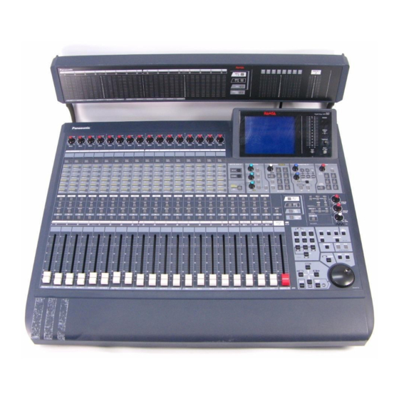
Application Guide Version 2 Audio Mixer WR-DA7 The meter bridge shown in photo is one of the optional accessories. - Page 2 ADAT is a registered trademark of Alesis Corporation TDIF is copyrighted by TEAC Corporation and TASCAM is a registered trademark of TEAC Corporation IBM is a registered trademark of International Business Machines Corporation Mac is a registered trademark of Apple Computer, Inc.
-
Page 3: Table Of Contents
1. Introduction ... 4 2. Notes for connections with peripheral equipment... 5 2.1 Wordclock ... 5 2.2 Installing and using option cards with the WR-DA7 ... 5 2.3 ADAT, BRC ... 8 2.4 DA-98, 88, 38 ... 9 2.5 DAT (with AES/EBU or S/PDIF I/O) ...11 2.6 Digital timepiece...11... -
Page 4: Introduction
This Application Guide supplies examples for interfacing the WR-DA7 with commonly used peripheral recording equipment. This guide’s diagrams provide the necessary connections and the methods for establishing proper system operation. WORD CLOCK IN (75 =OFF) WORD SYNC OUT (BNC) MIDI... -
Page 5: Notes For Connections With Peripheral Equipment
2 track A input [2TR IN A] and Slot 1,2 or 3. For example: it is possible to select the WR-AESS card as the wordclock source of the WR-DA7. The DA7 can be synchronized with the digital audio signals being input on Channels 1/2 of the WR-AESS card. - Page 6 The WR-DA7 allows ON/OFF of the 75-Ohm terminator on the wordclock input. ON: Is selected when the WR-DA7 is used as a wordclock master or as a slave at the end of the wordclock connections (terminated at 75 Ohm). (A clock output synchronized with DA7 is generated at the word clock’s output.)
- Page 7 MASTER: When used with the tandem master unit. SLAVE: When used with the tandem slave unit. To connect two WR-DA7 mixers in Tandem, install a WR-TNDM card in Slot 3 of each mixer (with the mixers powered OFF). Select MASTER/SLAVE on the front panel of each WR-TNDM card.
-
Page 8: Adat, Brc
The ADATs must be powered-up before the BRC. The BRC should be turned on last. Wordclock If the ADAT is being used as the wordclock master set the ADAT wordclock to INT. The WR-DA7 functions as an ADAT SLAVE. The WR-DA7 wordclock settings can be set by pressing the D-I/O switch to display the INPUT SET window of the D-I/O setup section. - Page 9 2.4 DA-98, 88, 38 Connections When making connections between the DA98, 88, 38 and the WR-DA7, use the WR-TDIF option card and make the connections using the Panasonic part # DA/DB-TDIF(Available in the USA) or use Part # PW-88D (1m) or PW-88D-L (5m) made by TASCAM.
- Page 10 SYNC OUT terminal of the DA-88 to the WCK IN terminal of the WR-DA7. Then press the D-I/O switch of the WR-DA7 several times in order to display the INPUT SET screen of the D-I/O window. Then, select the SOURCE SELECT to ‘WCK IN.’...
-
Page 11: Dat (With Aes/Ebu Or S/Pdif I/O)
DTP . When the DTP is used as the MIDI interface with MMC from the WR-DA7 for the ADAT or the DA- 98, 88, or 38 connected through the DTP and the SYNC cable, the following operation takes place:... - Page 12 Normally, a Macintosh computer has two serial ports: modem and printer port. RAMSA MAX soft- ware permits connection of either of these ports to the WR-DA7. To control one WR-DA7, the modem port is normally used. To control two WR-DA7s, connect the WR-DA7 (serving as the mas- ter) to the modem port and the other one (serving as the slave) to the printer port.
- Page 13 Select [OMS MIDI Setup] in the Edit menu. Select the port (normally, the printer port) in which there's no WR-DA7 connected. (In this case, de-select [Modem] and [Run MIDI In background].) If OMS is started for the first time, the MIDI devices connected to the computer must be rec- ognized by the OMS.
-
Page 14: Wr-Da7 System Applications
WR-DA7 and firmly fasten them to the mixer using the supplied screws. Connect the WR-ADAT card of the WR-DA7 to the DIGITAL IN/OUT terminal of the ADAT using an optical cable and press the DIGITAL IN switch on the front panel of the ADAT to select the digital input mode. - Page 15 System configuration-1 WCK MASTER ADAT DIGITAL TRACK8 ANALOG OUT (RCA) WR-ADAT Optical Cable SLOT 1 (17-24ch) SMPTE IN WR-SMPT (XLR) WR-DA7 Power AES/EBU MONITOR A IN Sampler Keyboard Effector SEND INPUT 1-16...
-
Page 16: Example Of Systems For Adat (3Units) And Brc
BRC, and having the ADAT controlled by MMC from the WR-DA7. Method of connection With the mixer powered OFF insert the option card WR-ADAT in Slot 1, 2, 3 of the WR-DA7 and fas- ten them to the securely using the 4 screws. - Page 17 DA7 and the MMC’s MIDI channel of the BRC. On the BRC, obtain a display of 11: MIDI Device screen by MIDI/UTIL setting. Set the value of ‘MIDI channel set for the WR-DA7 - 1.’ Otherwise, set- ting should be set to ‘ALL.’...
- Page 18 (48kHz OUT) (75 =ON) DIGITAL WR-ADAT Optical Cable SLOT 1 (17-24ch) DIGITAL WR-ADAT SLOT 2 Optical Cable (25-32ch) DIGITAL WR-ADAT WR-ADAT SLOT 3 Optical Cable (9-16ch) Power AES/EBU MIDI MIDI MONITOR A IN WR-DA7 Keyboard Effector SEND INPUT 1-8 Sampler...
-
Page 19: Example Of Systems With Two Wr-Da7 In Tandem With 4 Adats And Brc
Set the switch on the front of WR-TNDM card to MASTER for the WR-DA7 that is to being used as a master unit. Set switch on the card to SLAVE of the WR-DA7 being used as a slave unit. - Page 20 SETUP screen. For the TANDEM SLAVE unit, set the SEND/RECEIVE of the various MIDI messages to ‘THRU.’ For MTC reception on the WR-DA7, set MTC PORT to ‘MIDI’ in the MIDI SETUP screen of the TANDEM Master unit. To obtain the MTC timecode display on the LCD screen set the TIME BASE to ‘MTC’ in the AUTOMATION EXECUTE screen of the Automation SETUP SECTION.
- Page 21 To accomplish MMC operation, the MIDI channel of the WR-DA7 and the MIDI channel of the BRC must be set to the same channel. On the BRC, obtain a display of 11: MIDI Device screen by MIDI/UTIL setting. Set the value of ‘MIDI channel set for the WR-DA7 - 1.’ Otherwise, the settings should be set to ‘ALL.’...
-
Page 22: System Configuration
WR-SMPT (BNC) (XLR) DIGITAL WR-ADAT SLOT 1 Optical Cable (17-24ch) DIGITAL WR-ADAT SLOT 2 Optical Cable (25-32ch) (MASTER) WR-TANDM WR-DA7 SLOT 3 (MASTER) MIDI WR-TANDM (SLAVE) SLOT 3 DIGITAL WR-ADAT SLOT 1 Optical Cable (17-24ch) DIGITAL WR-ADAT Optical Cable SLOT 2... -
Page 23: Example Of Systems With 3 Da-88S
Machine Control) from the WR-DA7. Method of connection With the DA7 powered OFF insert the WR-TDIF (option card) in Slot 1, 2, 3 of the WR-DA7 and firmly fasten them to the console with the supplied screws. Using the dip switches on the WR-TDIF card make the proper setting for the DA-88 (SW1, 2 to OFF, OFF respectively). - Page 24 No playback is produced when ALL INPUT is ON; For playback, ALL INPUT should be set to OFF. For MMC control of the DA-88 from the WR-DA7, set the MODE dip switch #2 to 0 (OFF) on the rear panel of the SY-88 in order to make the MIDI port effective.
- Page 25 (BNC) WORD SYNC OUT (BNC) TDIF-1 TDIF-1 WR-TDIF PW-88DL SLOT 1 (17-24ch) TDIF-1 TDIF-1 WR-TDIF PW-88DL SLOT 2 (25-32ch) TDIF-1 TDIF-1 WR-TDIF PW-88DL SLOT 3 (9-16ch) Power AES/EBU MIDI MIDI MONITOR WR-DA7 Sampler Keyboard Effector A IN SEND INPUT 1-8...
-
Page 26: Example Of Systems For Wr-Da7 Tandem Connections With Da-98(1Unit) And Da-38(3Units)
Set the dip switches on the WR-TDIF card of the DA-98 and 38 (both SW1, 2 at ON, OFF). Set the rear switch of the WR-TNDM card to MASTER for the WR-DA7 that is to be used as a master unit and set the slave WR-DA7 to SLAVE. - Page 27 WR-DA7 setting To use the WR-DA7 as a slave unit, set the SOURCE SELECT to ‘WCK IN’ in the INPUT SET window of the D-I/O Setup Section on the MASTER unit. (For wordclock synchronization using the DA98’s connection slot, set the SOURCE SELECT to ‘SLOT1’...
- Page 28 (BNC) MIDI TDIF-1 TDIF-1 WR-TDIF PW-88DL SLOT 1 (17-24ch) TDIF-1 TDIF-1 WR-TDIF PW-88DL SLOT 2 (25-32ch) WR-TANDM (MASTER) SLOT 3 WR-DA7 (MASTER) WR-TANDM (SLAVE) SLOT 3 TDIF-1 TDIF-1 WR-TDIF PW-88DL SLOT 1 (17-24ch) TDIF-1 TDIF-1 WR-TDIF PW-88DL SLOT 2 (25-32ch)
-
Page 29: Example Of Systems For Analog 16-Track Recorder(1Unit)
Set the WR-DA7 to the wordclock master. In the INPUT SET screen of D-I/O of the WR-DA7, set SOURCE SELECT to ‘INT 48k’ or ‘INT 44.1k.’ To display the SMPTE timecode being received at the SMPTE IN, set the TIME BASE to ‘SMPTE’ in... - Page 30 System configuration -6 16Track Analog Multitrack Recorder Track16 Analog Out WCK MASTER WR-ADDA SLOT 1 (17-24ch) WR-ADDA SLOT 2 (25-32ch) SMPTE IN WR-SMPT (XLR) WR-DA7 Power AES/EBU MONITOR A IN SEND Sampler Keyboard Effector INPUT 1-16...
-
Page 31: Example Of Systems For Digital Video Recorder (1Unit)
SMPTE timecode from the Digital Video Recorder for it’s editing and automation operations. Method of connection Insert the option card of WR-AESS (Slot 1) and the WR-SMPTE (option card) in the WR-DA7 and fasten them to the console using the supplied screws. Select the switches on the WR-AESS card to AES/EBU. - Page 32 WCK MASTER House Video Sync SW-OFF (BNC) SMPTE OUT (XLR) DIGITAL IN/OUT (XLR) Digital Video Recorder V-SYNC IN(BNC) WR-SMPT SMPTE IN(XLR) SLOT 1 (17-24ch) DIGITAL WR-AESS (D-sub SW=AES/EBU 25pin) WR-DA7 Power AES/EBU MONITOR A IN SEND Sampler Keyboard Effector INPUT 1-16...
-
Page 33: Example Of Systems For Vtr (1Unit), Adat (1Unit), And Brc
Method of connection Insert the option card WR-ADAT in Slot 1 of the WR-DA7 and firmly fasten it to the Da7 with the supplied screws. Connect the WR-ADAT card from the WR-DA7 to the DIGITAL IN/OUT of the ADAT using an optical cable and press the DIGITAL IN switch on the ADAT’s front panel to select the digital input mode. - Page 34 To accomplish MMC operation, there must be coincidence of the MIDI channel between MMC output from the WR-DA7 and MMC received on the BRC. On the BRC, set the display to 11: MIDI Device screen by MIDI/UTIL setting. Set the value of ‘MIDI channel set for the WR-DA7 - 1.’...
- Page 35 MIDI IN MIDI OUT WCK OUT WORD CLOCK IN (48kHz OUT) (75 =ON) SMPTE OUT (Phone) WR-SMPT SMPTE IN (XLR) WCK MASTER DIGITAL WR-ADAT WR-ADAT Optical Cable SLOT 1 (17-24ch) Power MONITOR REC OUT WR-DA7 Keyboard Effector SEND INPUT 1-16 Sampler...
-
Page 36: Example Of Systems For Vtr (1Unit) And Da-98 (1Unit)
Method of connection With the DA7 powered off, insert the option card WR-TDIF in Slot 1 of the WR-DA7 and firmly fas- ten it to the mixer with the supplied screws. Make the setting for the DA-88 with the dip switches on the WR-TDIF card (SW1, 2 to OFF, respectively). - Page 37 To enable the DA-98 to receive digital input from the TDIF-1, press the DIGITAL IN button on the front panel. When the timecode output of the video recorder is generated after being converted to MTC, the MODE dip switch 6 on the SY-88 rear side is set to OFF. (If this switch is set to ON, the timecode recorded on the tape is converted into MTC and the resultant output is generated.) Use the tape where the recorded timecode has the same frame rate as that of the SMPTE timecode output generated from the video.
- Page 38 House Video Sync SMPTE Timecode MIDI TIMECODE VIDEO IN DA-98 WORD SYNC OUT (BNC) Monitor VIDEO REC OUT MIDI IN MIDI OUT MIDI TDIF-1 TDIF-1 WR-TDIF PW-88DL WORD CLOCK IN (75 =ON) (BNC) Power MONITOR SEND WR-DA7 Keyboard Effector INPUT 1-16 Sampler...
-
Page 39: System Example Of Pro Tools
MIDI cable routing. WR-DA7 Setup Set the [Source Select] to [WCK IN] in the Input Set screen of D-I/O to set the WR-DA7 as slave. To receive MTC timecode, set [MTC Port] to [MIDI} in the MIDI Setup screen. - Page 40 BRC's MIDI/UTIL setup menu to [ON]. To operate MMC, the MMC MIDI channels of the WR-DA7 and BRC must be set the same. On the BRC, set item 11 [MIDI Device] on the MIDI/UTIL setup menu to "(the MIDI channel set by the...
- Page 41 PORT 2 OUT MIDI WORD CLOCK IN WCK OUT WR-AESS (Dsub 25pin) SLOT 1 (17-24ch) DIGITAL WR-ADAT SLOT 2 Optical Cable (25-32ch) DIGITAL WR-ADAT Optical Cable SLOT 3 (9-16ch) WR-DA7 Power Effector S/PDIF MONITOR MIDI A IN SEND INPUT 1-8 Sampler Keyboard...
-
Page 42: System Example Of Pc Sequencer (Performer)
MIDI cable to control the ADAT using MMC. Then connect the MIDI OUT of the BRC to port 2 MIDI IN of the MIDI Timepiece A/V with a MIDI cable to operate the WR-DA7 and Pro Tools in ref- erence to the BRC's timecode. - Page 43 MTC] on the BRC MIDI/UTIL setup menu to [ON]. To operate the MMC, the MMC and MIDI channels of the WR-DA7 and BRC must be set the same. On the BRC, set items 11 [MIDI Device] on the MIDI/UTIL setup menu to "the MIDI channel set by...
-
Page 44: To Pc Sequencer (Performer)
WR-ADAT SLOT 1 Optical Cable (17-24ch) DIGITAL WR-ADAT SLOT 2 Optical Cable (25-32ch) DIGITAL WR-ADAT WR-ADAT SLOT 3 Optical Cable (9-16ch) Power AES/EBU MIDI MIDI MONITOR A IN WR-DA7 INPUT 1-8 MIDI IN Sampler MIDI IN Keyboard Effector S/PDIF SEND... - Page 45 With the WR-DA7 powered "OFF". Insert the WR-TNDM cards into slot 3 of each of the WR-DA7s, and fasten them securely using the supplied screws. Set the switch on the back of the WR-TNDM card of the master WR-DA7 to [Master] and set the same switch on the slave WR-DA7 to [Slave].
- Page 46 To use System Exclusive set [Tx, Rx] to [ON] in the System EX setup area in the MIDI setup screen. To have the WR-DA7 receive MTC, set the [MTC Port] to [MIDI] in the MIDI Set up area of the MIDI setup screen for the tandem master WR-DA7.
- Page 47 To record the operations of both the WR-DA7 master and slave on the MIDI sequencer (Performer), select [Multi Record] on the mini-menu of the track screen of the MIDI sequencer. Then set the two track into record mode on the track screen, and set each [Input] to [WR-DA7 (Master)] and [WR-DA7 (Slave)].
- Page 48 (75 =OFF) DIGITAL WR-ADAT Optical SLOT 1 Cable (17-24ch) DIGITAL WR-ADAT Optical SLOT 2 Cable (25-32ch) WR-TANDM SLOT 3 (MASTER) WR-DA7 (MASTER) MIDI IN SLOT 3 WR-TANDM (SLAVE) MIDI IN MIDI OUT DIGITAL WR-ADAT Optical SLOT 1 Cable (17-24ch) DIGITAL WR-ADAT...
-
Page 49: System Example Of Akai Dr8 (1 Unit)
MTC functions operational. WR-DA7 Setup Set the [Source Select] to [Slot 1] on the Input Set screen of D-I/O to set the WR-DA7 as the word- clock slave. To use MMC set the [MMC Port] to [MIDI] in the MIDI Setup screen. - Page 50 System Configuration-13 WCK MASTER with IB-804A (IB-803M) DIGITAL Optical Cable SMPTE MIDI MIDI Power WR-ADAT SLOT 1 (17-24ch) MIDI IN MIDI OUT SMPTEIN WR-SMPT (XLR) WR-DA7 AES/EBU Effector S/PDIF MONITOR SEND A IN INPUT 1-16 Sampler Keyboard...
-
Page 51: Connection To Max (Macintosh) Expansion Software
For the MMC control of the DA-98 serving as the timecode master from the WR-DA7, connect the MIDI OUT of the WR-DA7 to the MIDI IN of the DA-98 and MIDI IN of the WR-DA7 to MIDI OUT of the DA-98 using standard MIDI cables. - Page 52 System Configuration-14 Expansion Software WCK MASTER MIDI MIDI DA-98 (Mac) Printer Port MIDI IN MIDI OUT TDIF-1 TDIF-1 WR-TDIF PW-88DL SLOT 1 (17-24ch) WR-DA7 Power AES/EBU MONITOR A IN To PC Sampler Keyboard INPUT 1-16...
-
Page 53: Connection To Max (Macintosh) Expansion Software And Other Sequence Software
DA-98, set [MMC Port] to [MIDI] and match [MIDI CH] with the MIDI/bus ID of the DA-98. MIDI Timepiece A/V Setup To send the MTC received from the DA-98 to the WR-DA7, establish a connection from Port 4 IN to Port 3 OUT. - Page 54 Similarly, select [WR-DA7 Timecode Input] as a sync source on the preference port setup menu. Then, select a check mark for [Receive Timecode] on the Real-time menu so that MTC can be received from the DA-98 via the WR-DA7.
- Page 55 IN/OUT MIDI DA-98 PORT 3 OUT MIDI IN MIDI OUT MIDI WCK MASTER TDIF-1 TDIF-1 WR-TDIF PW-88DL SLOT 1 (17-24ch) Power AES/EBU MONITOR To PC WR-DA7 MIDI IN MIDI OUT Sampler MIDI IN MIDI OUT Keyboard A IN INPUT 1-16...
-
Page 56: Tandem-Connection To Max (Macintosh) Expansion Software
Set the switch on the back of the WR-TNDM card in the master WR-DA7 of the tandem system to [Master] and select slave on the WR-DA7 to act as the [Slave]. - Page 57 When [OK] is pressed in the [Preference] dialog, the expansion software loads the setup data from the master and slave. To receive timecode set the [Sync Source] to [WR-DA7 Timecode Input] in the Preference Port Setup area of the Edit menu. Then, enter a check mark at the [Receive Timecode] in the Real-time...
- Page 58 MIDI MIDI TDIF-1 TDIF-1 WR-TDIF PW-88DL SLOT 1 (17-24ch) TDIF-1 TDIF-1 WR-TDIF PW-88DL SLOT 2 (25-32ch) WR-TANDM (MASTER) SLOT 3 WR-DA7 (MASTER) WR-TANDM (SLAVE) SLOT 3 TDIF-1 TDIF-1 WR-TDIF PW-88DL SLOT 1 (17-24ch) TDIF-1 TDIF-1 WR-TDIF PW-88DL SLOT 2 (25-32ch)
-
Page 59: Tandem-Connection To Max (Macintosh) Expansion Software
Insert the WR-TNDM card into slot 3 of each of the two WR-DA7s, and fasten the cards securely with the screws. Set the switch on the back of the WR-TNDM card in the master WR-DA7 of the tandem system to [Master] and the same switch on the same card in the slave WR-DA7 to [Slave]. - Page 60 When [OK] is pressed in the [Preference] dialog box, the expansion software loads the setup data of the master and slave. To receive timecode set [Sync Source] to [WR-DA7 Timecode Input] in the Preference Port Setup item of the Edit menu. Then, enter a check mark at [Receive Timecode] on the Real-time menu.
- Page 61 MIDI Sequencer (Digital Performer) Setup To receive MTC from the DA-98 through the MIDI Timepiece A/V , set the Sync Port to [Modem] in the Receive Sync area in the Basic menu, and set the [Type of Sync] to [MTC, DTL or DTLe]. Then, set the [Slave to External Sync] to [ON] in the Basic menu and press the [Play] button on the control panel.
- Page 62 MIDI TDIF-1 TDIF-1 WR-TDIF PW-88DL SLOT 1 (17-24ch) TDIF-1 TDIF-1 WR-TDIF PW-88DL SLOT 2 (25-32ch) WR-TANDM SLOT 3 (MASTER) WR-DA7 (MASTER) MIDI IN MIDI OUT WR-TANDM (SLAVE) SLOT 3 TDIF-1 TDIF-1 WR-TDIF PW-88DL SLOT 1 (17-24ch) TDIF-1 TDIF-1 WR-TDIF PW-88DL...
- Page 63 aV0599-1069 DA7AppliGuide Printed in Japan Matsushita Communication Industrial Co., Ltd. 1999...