Garmin GTX 330 Installation Manual
Hide thumbs
Also See for GTX 330:
- Installation manual (86 pages) ,
- System maintenance manual (56 pages) ,
- Pilot's manual (13 pages)

Related Manuals for Garmin GTX 330


Summary of Contents for Garmin GTX 330
- Page 1 GTX 330/330D Transponder Installation Manual 190-00207-02 December, 2013 Revision U...
- Page 2 Garmin. Garmin hereby grants permission to download a single copy of this manual and of any revision to this manual onto a hard drive or other electronic storage medium to be viewed and to...
- Page 3 Added reference to verifying ADS-B Out functionality 5-10 5.2.7 Added display contrast info 5-19 5.2.14 Updated GPS config page info 5-21 5.2.17 Added ADS-B TX settings info D-1–D-18 Appdx D Updated Figures D-1 through D-14 190-00207-02 GTX 330/330D Installation Manual Rev. U Page i...
- Page 4 NOTE Throughout this document references made to GTX 330 shall equally apply to the GTX 330 and the GTX 330D except where specifically noted. GTX 330/330D Installation Manual...
- Page 5 GTX 330 HARDWARE MOD LEVEL HISTORY The following table identifies hardware modification (Mod) Levels for the GTX 330 and GTX 330D Mode S Transponders. Mod Levels are listed with the associated service bulletin number, service bulletin date, and the purpose of the modification.
- Page 6 (iv) damage caused by service performed by anyone who is not an authorized service provider of Garmin; or (v) damage to a product that has been modified or altered without the written permission of Garmin. In addition, Garmin reserves the right to refuse warranty claims against products or services that are obtained and/or used in contravention of the laws of any country.
-
Page 7: Table Of Contents
2.5 Cabling and Wiring Considerations................. 2-4 2.6 Installation Approval Considerations for Pressurized Aircraft........2-5 2.7 Cooling Air ........................2-5 2.8 GTX 330 Installation ....................... 2-5 Section 3 INSTALLATION PROCEDURE ............ 3-1 3.1 Unpacking Unit........................ 3-1 3.2 Wiring Harness Installation ..................... 3-1 3.3 Circuit Breaker Placard.................... -
Page 8: Paragraph Page
A.1 STC Permission ......................A-1 A.2 Continued Airworthiness ....................A-3 Appendix B VERSION 1 ADS-B FIELD APPROVAL COMPLIANCE MATRIX ..................B-1 Appendix C ASSEMBLY AND INSTALLATION DRAWINGS ....C-1 Appendix D INTERCONNECT DRAWINGS..........D-1 GTX 330/330D Installation Manual 190-00207-02 Page vi Rev. U... - Page 9 Figure C-3 GTX 330 Recommended Panel Cutout Dimensions ..........C-3 Appendix D INTERCONNECT DRAWINGS ..........D-1 Figure D-1 GTX 330 to 400/500 Series Units, Typical Interconnect Wiring Diagram ..D-1 Figure D-2 GTX 330 to GNS 480(CNX80), Typical Interconnect Wiring Diagram..D-2 Figure D-3 GTX 330 to GNS 480 (CNX80) and MFD, Simplified Interconnect Wiring Diagram ........................
- Page 10 Figure D-11 GTX 330 w/ES to GDL 90 Connections............D-15 Figure D-12 GTX 330 to 400/500 Series Units ADS-B Interconnect ....... D-16 Figure D-13 GTX 330 to 400W/500W Series Units ADS-B TX Only Interconnect ..D-17 Figure D-14 GTX 330 to GTN 6XX/7XX Simplified Interconnect Wiring Diagram ..D-18...
- Page 11 Table 5-3 Display Mode Selections..................5-7 Table 5-4 Display Backlight Selections................5-7 Table 5-5 Backlight Source Selections ................. 5-8 Table 5-6 Key Lighting Selections ..................5-9 Table 5-7 Key Source Selections..................5-9 190-00207-02 GTX 330/330D Installation Manual Rev. U Page ix...
- Page 12 Table 5-25 Received Labels and Data from EFIS Display..........5-24 Table 5-26 Received Labels and Data from GPS/FMS ............5-25 Table 5-27 Received Labels and Data from Garmin Display..........5-25 Table 5-28 Received Labels and Data from ARINC 743A ..........5-26 Table 5-29 Received Labels and Data from AFCS ............
-
Page 13: Section 1 General Description
This manual is intended to provide mechanical and electrical information for use in the planning and design of an installation of the GTX 330 into an aircraft. This manual is not a substitute for an approved airframe-specific maintenance manual, installation design drawing, or complete installation data package. -
Page 14: Ads-B Capabilities
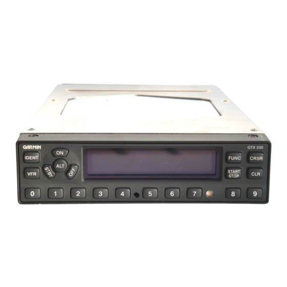
ARINC 429 output bus used by display systems such as the Garmin 400 Series/500 Series units. The GTX 330 is configured with all key controls. The layout of the front panel keys and displays segregates the transponder’s primary functions from the secondary functions. The unit can be configured so the aircraft avionics master bus can turn the unit on. - Page 15 1. Installers may elect to disable the ADS-B Extended Squitter function, as described in Section 5.2.17. 2. Installers may utilize a Supplemental Type Certificate (STC) for the GTX 330 with the Version 1 ADS-B Extended Squitter activated. 3. Installers may obtain a field approval with the Version 1 ADS-B Extended Squitter activated.
-
Page 16: Tis System Capabilities
Advisory traffic information is available to aircraft equipped with a Mode S data link such as the Garmin GTX 330 transponder. Advisory traffic information may be displayed on a Garmin 400/500 Series unit. -
Page 17: Interface Summary
BDS register information is presented for the installation agency to understand the functionality of the GTX 330, and make a determination that the unit complies with the requirements of their civil aviation authorities. No further wiring or configuration programming is required for the unit. -
Page 18: Technical Specifications
1.7 Technical Specifications 1.7.1 Environmental Qualification Form It is the responsibility of the installing agency to obtain the latest revision of the GTX 330 Environmental Qualification Form. The form is available directly from Garmin under the following part number: GTX 330/GTX 33/GTX 328/GTX 23 Environmental Qualification Form, Garmin part number 005-00131-03 To obtain a copy of this form, see the dealer/OEM portion of the Garmin web site (www.garmin.com). -
Page 19: Table 1-3 Physical Characteristics
11.25 inches (286 mm) aircraft panel to rear of connector backshells) GTX 330 Unit Weight 3.4 lbs. (1.5 kg) GTX 330 Rack Weight (Installed with rack and connectors) 4.2 lbs. (1.9 kg) 1.7.4 Power Requirements Table 1-4 Power Requirements Characteristic Specification 14/28 Vdc. -
Page 20: Certification
The article may be installed only if performed under 14 CFR Part 43 or the applicable airworthiness requirements. For GTX 330 TSO compliance and STC, see Appendix A. For antenna TSO compliance, refer to antenna manufacturer’s literature. - Page 21 2. Complies with TSO-C166a/ETSO-C166a functionality only when the Extended Squitter function is enabled during configuration (refer to Section 3. Complies with TSO-C166b functionality only when the Extended Squitter function is enabled during configuraton (Section 190-00207-02 GTX 330/330D Installation Manual Rev. U Page 1-9...
-
Page 22: Operating Instructions
If an aircraft license is required, make application for a license on FCC form 404, Application for Aircraft Radio Station License. The FCC also has a fax-on-demand service to provide forms by fax. The GTX 330 owner accepts all responsibility for obtaining the proper licensing before using the transponder. -
Page 23: Section 2 Installation Overview
This section provides hardware equipment information for installing the GTX 330 Mode S Transponder, related hardware and optional accessories. Installation of the GTX 330 should follow the data detailed in this manual. Cabling is fabricated by the installing agency to fit each particular aircraft. The installation should follow the guidance of FAA Advisory Circulars AC 43.13-1B and AC 43.13-2B where applicable. -
Page 24: Installation Considerations
P/N 013-00066-00) can provide altitude data in either serial or parallel gray code format. 2.3 Installation Considerations The GTX 330 can interface with equipment including altimeters, Air Data Computer (ADC) and a temperature probe. RS-232 and ARINC 429 provide a serial communication path between interfacing equipment. -
Page 25: Antenna Installation
2.6) Figure 2-1 Antenna Installation Considerations 1. The antenna(s) (Garmin P/N 010-10160-00) should be mounted away from major protrusions, such as engine(s), propeller(s), and antenna masts. It should also be as far as practical from landing gear doors, access doors, or other openings that could effect its radiation pattern. -
Page 26: Cabling And Wiring Considerations
See current issue of shown for St. Augustine, FL 32092 Supplier Information Qualified Products List reference only; Tel: 800-458-9960 QPL-17. replaced by M17 904-829-5600 type numbers. Fax: 904-829-3447 wwwcarlisleit.com GTX 330/330D Installation Manual 190-00207-02 Page 2-4 Rev. U... -
Page 27: Installation Approval Considerations For Pressurized Aircraft
2.7 Cooling Air The GTX 330 meets all applicable TSO requirements without forced air cooling. The application of forced air cooling to the rear air nozzle of the GTX 330 is highly recommended to provide beneficial cooling to the unit. -
Page 28: Figure 2-2 Gtx 330 Unit Rack (115-00294-00)
4. Turn the hex wrench clockwise until unit is secured in the rack. Continue turning until tight. Do not over-tighten the screw. 5. To remove the unit from the rack, turn the 3/32” hex wrench counterclockwise until it disengages from the rack. Figure 2-2 GTX 330 Unit Rack (115-00294-00) GTX 330/330D Installation Manual 190-00207-02 Page 2-6... -
Page 29: Section 3 Installation Procedure
If the unit is damaged, notify the carrier and file a claim. To justify a claim, save the original shipping container and all packing materials. Do not return the unit to Garmin until the carrier has authorized the claim. -
Page 30: Circuit Breaker Placard
M81969/1-04 615725 M81969/1-04 1) Non-Garmin part numbers shown are not maintained by Garmin and consequently are subject to change without notice. 2) Extracting the #18 or #20 contact requires that the expanded wire barrel be cut off from the contact. -
Page 31: Section 4 System Interconnects
RS-232 OUT 2 ARINC 429 IN 3 A POWER GROUND ARINC 429 OUT 2 B ARINC 429 IN 3 B ARINC 429 OUT 2 A *Denotes Active Low (Ground to activate) 190-00207-02 GTX 330/330D Installation Manual Rev. U Page 4-1... - Page 32 ARINC 429 IN 4 B ALTITUDE COMMON (GROUND) SIGNAL GROUND RESERVED RESERVED RESERVED SPARE AIRCRAFT POWER 2 SPARE RESERVED SPARE AIRCRAFT POWER 2 SPARE SWITCHED POWER OUT *Denotes Active Low (Ground to activate) GTX 330/330D Installation Manual 190-00207-02 Page 4-2 Rev. U...
-
Page 33: Power And Lighting Function
4.2.2 Lighting Bus The GTX 330 unit can be configured to track a 28 Vdc, 14 Vdc, 5 Vdc or 5 Vac lighting bus using these inputs. The GTX 330 can also automatically adjust for ambient lighting conditions based on the photocell. -
Page 34: Altitude Functions
25-foot increments the GTX 330 must receive altitude from suitable altitude reporting devices through serial input connections. Altitude input to the GTX 330 received from parallel wire gray code encoders is supplied to the unit in 100-foot increments and thus reported in 100-foot increments. -
Page 35: Figure 4-2. Dual Gtx 330, Single Encoder, Serial Input Connections
4.4.3 Altimeter Interconnect, Dual GTX 330 Installation A dual GTX 330 installation can accept either parallel wire gray code altimeter input or RS-232 serial data input as shown in Figure 4-2. If transponder number 2 is a Garmin GTX 327, connect the RS-232 output from the altitude encoder to J3271 pin 19 (refer to GTX 327 Transponder Installation Manual, P/N 190-00187-02). -
Page 36: Discrete Functions
The installer must be aware of the GTX 330 priority for selecting encoded altimeter interconnections. The GTX 330 searches in this sequence for altitude, and stops when it finds a valid pressure altitude input. Only approved devices may provide altitude to the GTX 330 in accordance with 14 CFR 91.217. In addition, all altitude reporting devices installed in the aircraft must meet certification requirements of 14 CFR 91.413. -
Page 37: Serial Data Electrical Characteristics
When TIS CONNECT SELECT is inactive (“Standby” is displayed on the 400/500 Series units) the GTX 330 logs onto TIS service when a momentary ground is applied to J3301-46. When TIS is active, a momentary ground logs off of TIS service. Refer to... -
Page 38: Table 4-8 Rs-232 Pin Assignments
RS-232 serial data configuration. When connecting two GTX 330 transponders to a GPS, the unit can only receive RS-232 serial data from one unit at a time. Use a DPDT switch for connecting both serial data and External Standby Select. Refer Figure D-9, Sheets 2 and 3. -
Page 39: Figure 4-3. Gtx 330 Software Update Connections
TIS and TCAD/TCAS, both systems cannot be connected to the same 400/500 Series unit to display traffic simultaneously. In a multiple traffic system/multiple 400/500 Series unit installation, connect ARINC 429 CHANNEL 1 from the GTX 330 to only one of the 400/500 Series units and ARINC 429 CHANNEL 2 to the other 400/500 Series unit. -
Page 40: Table 4-10 Arinc 429 Pin Assignments
GTX 330/GTX 327 (or GTX 330/other transponder), the GARMIN and GARMIN W/TIS formats from the ARINC 429 Output 1 port, J3301 pins 34 and 37, are available if the GTX 330 has SW 3.03 and above. Table 4-10 ARINC 429 Pin Assignments... -
Page 41: Section 5 Post Installation Configuration And Checkout Procedure
5.1 Operation NOTE The coverage you can expect from the GTX 330 is limited to line of sight. Low altitude or antenna shielding by the aircraft itself may result in reduced range. Range can be improved by climbing to a higher altitude. It may be possible to minimize antenna shielding by locating the antenna where dead spots are only noticed during abnormal flight attitudes. - Page 42 5.1.1 Function Selector Switches The function selection switches are: OFF Powers off the GTX 330. Pressing the STBY, ON or ALT key powers on the • transponder displaying the last active identification code. STBY Selects the standby mode. When in standby mode, the transponder does not •...
-
Page 43: Code Selection
Avoid selecting code 7500 and all codes in the 7600-7777 range. These codes trigger special indicators in automated facilities. An aircraft’s transponder code is used for ATC tracking purposes, therefore exercise care when making routine code changes. 190-00207-02 GTX 330/330D Installation Manual Rev. U Page 5-3... -
Page 44: Configuration
(EHS). NOTE When connecting the GTX 330 to a NAV/COM/GPS unit such as a GNS 480 (CNX80) or GTN 6XX/7XX unit, the transponder can be configured from either the NAV/COM/GPS unit or the GTX 330. Although possible from the NAV/COM/GPS unit, configuration from the GTX 330 front panel offers more functions and easier to interpret displays. - Page 45 Press the CRSR key and sequence through to the desired selection with the 8 and 9 keys. Jump to the selection by pressing the CRSR key again with the desired selection highlighted. 190-00207-02 GTX 330/330D Installation Manual Rev. U Page 5-5...
-
Page 46: Table 5-1 Configuration Menu Selections
6 through 9 are not used at this time. ALTITUDE MONITOR Off, tone or message COUNT DOWN TIMER Off, tone or message PAGE CHANGE Enables/Disables Altitude Monitor sub page when altitude deviation is exceeded. GTX 330/330D Installation Manual 190-00207-02 Page 5-6 Rev. U... -
Page 47: Table 5-3 Display Mode Selections
When AUTO is selected, the DISPLAY page does not appear to the pilot. Display backlighting is controlled manually by the pilot on the GTX 330 DISPLAY page. No MAN (Manual) backlight parameters can be entered when the manual mode is selected. -
Page 48: Table 5-5 Backlight Source Selections
DEFAULT. Backlight level is determined by the ambient light level as PHOTO (Photocell) measured by the photocell on the GTX 330. Backlight level tracks a 14 Volt DC aircraft lighting bus. Backlight level tracks a 28 Volt DC aircraft lighting bus. -
Page 49: Table 5-6 Key Lighting Selections
DESCRIPTION Key lighting is automatically controlled based on the parameters entered on AUTO (Automatic) this configuration page. Key lighting is controlled manually by the pilot on the GTX 330 DISPLAY MAN (Manual) page. LVL (Level) Shows the current level of key lighting, based on the lighting input source (lighting bus voltage, or the ambient light if the source is PHOTO) and the settings on this configuration page. -
Page 50: Table 5-8 Contrast Mode Selections
MAN (Manual) Display contrast is manually adjusted either here or by the pilot using the GTX 330 CONTRAST page. CONTRAST LEVEL ADJUSTMENT This is a “slider” bar graph control. Use the 8 key to move the graph to the left, decreasing the numbers and contrast level. -
Page 51: Table 5-10 Speed Selections
1 through 3. ADLP is included for future use. For a connection to a Garmin GTS 820 or GTS 850, GARMIN TAS (HIGH) must be selected. Barometric data is not included in the GARMIN TAS format. A separate barometric data source is required SPEED (Channel 1 –... -
Page 52: Table 5-12 Arinc Channel Selections
In aircraft having multiple traffic systems and multiple 400/500 Series units, configure ARINC 429 output CHANNEL 1 for GARMIN W/TIS and ARINC 429 output CHANNEL 2 for GARMIN. TIS is then enabled over CHANNEL 1. GTX 330/330D Installation Manual... -
Page 53: Table 5-13 Arinc Output Labels, Data, And Rates
The Garmin format is a data concentration function. The following data is sent out at specified intervals using high speed ARINC 429 (100 kHz). The transmit data labels and their rates are as follows: Table 5-13 ARINC Output Labels, Data, and Rates... -
Page 54: Table 5-15 Rs-232 Input Selections
GTN 6XX/7XX Installation Manual for configuration information for the GPS WAAS source. *For GTX 330 w/ES units with Software versions v7.01 or later (ADS-B Out Version 2), it is the installer’s responsibility to ensure the ADS-B Out system is compliant with AC 20-165 and to ensure compatibility between the GTX 330 and the ADS-B Out position source equipment. -
Page 55: Table 5-16 Rs-232 Output Selections
VFR ID (VFR Transponder Code) This field is the four-digit code that is selected when the user presses the GTX 330 VFR key. In the United States, 1200 is the VFR code for any altitude. The default is set to 1200. -
Page 56: Table 5-18 Auto Flight Timer Selections
DELAY TIME This is the number of seconds the aircraft must be on the ground before the GTX 330 automatically switches to GND mode when it has a means of determining the aircraft is on the ground. It has a range of 0 (zero) seconds to 99 seconds, with the default set to 24 seconds. -
Page 57: Table 5-19 Mode S Address Selections
NOTE It is not necessary for the installer to convert a US aircraft registration number (N-number) to a Hex address. The GTX 330 converts the US registration number to hexadecimal automatically. To select between Hex or Tail number, press the CRSR key, then 8 or 9 key to move to the correct selection. -
Page 58: Table 5-20 Flight Id Selections
Flight ID can be entered in TSO Class 2A units, P/N 010-00230-( ) and 010-00293-( ). NOTE When a Flight ID Number contains a space, the GTX 330 automatically removes spaces in data transmission. For operation requiring the flight crew to enter an aircraft identification designator each time the unit is powered up, select the page identified as FLIGHT ID PWR-UP ENTRY. -
Page 59: Table 5-21 Gps Configuration Page
The GPS INTEGRITY configuration field indicates the integrity of the GPS sensor that is connected to the GTX 330. It is measured in errors per flight hour, 1E-3 being the worst and 1E-7 being the best rating. This data is used in ADS-B transmissions. Check with the GPS manufacturer for guidance on this setting. -
Page 60: Table 5-22 Mode S Aircraft Type Selections
52.0 meters, less than or equal to 59.5 meters, less than or equal to 67.0 meters, less than or equal to 72.5 meters, less than or equal to 80.0 meters, or more then 80.0 meters. Enter the aircraft’s minimum width category. GTX 330/330D Installation Manual 190-00207-02 Page 5-20... - Page 61 This field displays the state of the EXTERNAL STANDBY discrete input. The box is filled when EXTERNAL STANDBY is grounded. If EXTERNAL STANDBY is active during power-up, the word FAIL appears on the screen after 30 seconds. 190-00207-02 GTX 330/330D Installation Manual Rev. U Page 5-21...
- Page 62 This field displays the input level of the 28 V lighting bus. This field displays the input level from the outside air temperature sensor. UNIT TEMP This field displays the input level from the unit temperature sensor. GTX 330/330D Installation Manual 190-00207-02 Page 5-22 Rev. U...
-
Page 63: Table 5-23 Received Labels And Data From Ahrs
(VFOMV) can be viewed 5.2.23 ARINC 429 Receive Channels Pages The GTX 330 receives one of the following sets of ARINC 429 data on either ARINC 429 receivers #1, #2 or #3. The ARINC 429 CHANNELS 1 and 2... -
Page 64: Table 5-24 Received Labels And Data From Adc
Vertical Speed (feet/min) Static Air Temperature (degrees) Barometric Setting (hPa) Barometric Setting (“Hg) Joystick Lat Joystick Lon True Heading Magnetic Heading (degrees) Roll Angle *If ADC W/ALT or EF/AD W/ALT format selected GTX 330/330D Installation Manual 190-00207-02 Page 5-24 Rev. U... -
Page 65: Table 5-26 Received Labels And Data From Gps/Fms
Label Data Selected Altitude (feet) Latitude (degrees) Longitude (degrees) Ground Speed (knots) Track Angle (degrees) GARMIN DISPLAY Table 5-27 Received Labels and Data from Garmin Display Label Data Discrete Data TAS Discrete Latitude (degrees) Longitude (degrees) Ground Speed (knots) Track Angle (degrees) -
Page 66: Enhanced Surveillance (Ehs)
Included are a list of parameters to other on-board avionics equipment formats that are accepted. The Req’d field denotes which formats are needed to make the GTX 330 system Mode S EHS capable. It is the responsibility of the installing agency to determine whether the equipment that interfaces with the Garmin GTX 330 Mode S transponder actually provides the required output. -
Page 67: Table 5-30 Required Ehs Equipment Connections
Note 2: Supplying either Indicated Airspeed or Mach is sufficient Mode S EHS compliance. Note 3: Supplying either True Airspeed or True Track Angle Rate is sufficient Mode S EHS compliance. 190-00207-02 GTX 330/330D Installation Manual Rev. U Page 5-27... -
Page 68: Section 5 5-1 –
This page intentionally left blank GTX 330/330D Installation Manual 190-00207-02 Page 5-28 Rev. U... -
Page 69: Appendix A Certification Documents
Installers may reference the following STC as evidence of initial airworthiness. Installers are hereby granted permission to refer to this STC. It should be noted, however, this STC is a 'one-only' STC 190-00207-02 GTX 330 Installation Manual Rev. U Page A-1... - Page 70 GTX 330 Installation Manual 190-00207-02 Page A-2 Rev. U...
-
Page 71: Continued Airworthiness
A.2 Continued Airworthiness Other than for regulatory periodic functional checks, maintenance of the GTX 330 is “on condition” only. Refer to the GTX 330 Maintenance Manual (Garmin P/N 190-00207-05). Periodic maintenance of the GTX 330 is not required. Refer to EASA ED Decision No 2003/19/RM, Annex II, Acceptable Means of Compliance to Part-145, Page 161. - Page 72 This page intentionally left blank GTX 330 Installation Manual 190-00207-02 Page A-4 Rev. U...
-
Page 73: Matrix
EASA AMC 20-24 requirements and corresponding compliance statements. For installations that utilize a Garmin GNS 400W/500W series, GTN 6XX/7XX series, or GNS 480 device (collectively referred to as ‘Garmin GNS equipment’), no additional data is required for the compliance matrix. -
Page 74: Table B-1 Compliance Matrix
Supported in BDS (6,5) Aircraft Operational Status. SPI data is sourced from Special Position Identification (SPI); transponder internal IDENT status. The IDENT function is controlled via GTX 330 or via remote located button. GTX 330/330D Installation Manual 190-00207-02 Page B-2 Rev. U... - Page 75 Requirement: 10 /fh (Appendix 3, Table 1) ____________________________ ____________________________ ____________________________ _____________ ADS-B System Continuity The GTX 330 meets the continuity Requirement: 2*10 /fh (Appendix 3, Table 1) requirement of 2*10 /fh. Horizontal Position Latency Requirement: 1.5 sec/95% (Appendix 3, Table See Item 28 Response.
- Page 76 Horizontal Position Source Integrity - Time to Other: Alert (Appendix 3, Table 2) ____________________________ Requirement: 5 NM Sep: 10 sec ____________________________ ____________________________ ____________________________ _____________ GTX 330/330D Installation Manual 190-00207-02 Page B-4 Rev. U...
- Page 77 Requirement: 1 sec (as for SSR) when the latency requirement for SSR is met. This data is sourced within the GTX 330 unit, based on internal Aircraft Identification, SPI, Emergency Status configuration settings, IDENT (Appendix 3, Table 3) status and Mode A code. Data...
- Page 78 Supported in BDS (6,5) Aircraft 8.3.1 Quality indicator (NACp) Operational Status. Supported in BDS (6,5) Aircraft 8.3.1 Quality indicator (SIL) Operational Status. Supported in BDS (6,5) Aircraft 8.3.1 Version Indicator Operational Status. GTX 330/330D Installation Manual 190-00207-02 Page B-6 Rev. U...
- Page 79 Velocity. For 1090 MHz Extended Squitter ADS-B transmit systems, this should be demonstrated by the relevant tests documented in: The GTX 330 is compliant with: 8.3.2 • ED-73B/ETSO-2C112b (or DO-181C); ETSO – 2C112b (DO-181C). • ED-102, as a minimum, or an equivalent ETSO –...
- Page 80 Table B-1 Compliance Matrix Item # AMC Item Compliance Summary Section # When two GTX 330 transponders are installed IAW requirements, simultaneous operation of both If more than one ADS-B transmit system is transponders is not possible. 8.3.8 installed, simultaneous operation of both Selection of the active transponder transmit systems needs to be prevented.
- Page 81 Fault Detection and 8.4.6.3 Exclusion capability as defined in AC 20-138A, Other: Appendix 1, “GPS as a Primary Means of ____________________________ Navigation for Oceanic/Remote Operations”. ____________________________ ____________________________ ____________________________ _____________ 190-00207-02 GTX 330/330D Installation Manual Rev. U Page B-9...
- Page 82 The performance of the encoders and of the months. sensors needs to be independent from the pressure setting selected. Therefore, an installation that meets the requirements for ATC transponders also meets this requirement. GTX 330/330D Installation Manual 190-00207-02 Page B-10 Rev. U...
- Page 83 For ATC transponder-based ADS-B transmit The IDENT key is available to the systems, the SPI capability needs to be pilot on the GTX 330. A remote provided. The SPI capability should be mounted IDENT button may also integrated into the transponder functionality and be installed.
- Page 84 Aircraft Identification information configuration settings established at when airborne. installation. The GTX 330 provides a means for Means should be provided to the flight crew to the pilot to disable ADS-B function disable the ADS-B function on instruction from 8.9.4.2...
-
Page 85: Appendix C Assembly And Installation Drawings
APPENDIX C ASSEMBLY AND INSTALLATION DRAWINGS Figure C-1 GTX 330 Outline Drawing 190-00207-02 GTX 330/330D Installation Manual Revision U Page C-1... -
Page 86: Figure C-2 Gtx 330 Connector/Rack Assembly Drawing
APPENDIX C ASSEMBLY AND INSTALLATION DRAWINGS Figure C-2 GTX 330 Connector/Rack Assembly Drawing 190-00207-02 GTX 330/330D Installation Manual Revision U Page C-2... -
Page 87: Figure C-3 Gtx 330 Recommended Panel Cutout Dimensions
APPENDIX C ASSEMBLY AND INSTALLATION DRAWINGS Figure C-3 GTX 330 Recommended Panel Cutout Dimensions 190-00207-02 GTX 330/330D Installation Manual Revision U Page C-3... -
Page 88: Figure D-1 Gtx 330 To 400/500 Series Units, Typical Interconnect Wiring Diagram
J5001 P5001 P5001 P4001/ P4001/ J4001/ J4001/ P5001 P5001 J5001 J5001 J3302 J3302 P3302 P3302 J3303 J3303 P3303 P3303 Figure D-1 GTX 330 to 400/500 Series Units, Typical Interconnect Wiring Diagram 190-00207-02 GTX 330/330D Installation Manual Revision U Page D-1... -
Page 89: Figure D-2 Gtx 330 To Gns 480(Cnx80), Typical Interconnect Wiring Diagram
APPENDIX D INTERCONNECT DRAWINGS J3301 J3301 P3301 P3301 J3302 J3302 P3302 P3302 J3303 J3303 P3303 P3303 Figure D-2 GTX 330 to GNS 480(CNX80), Typical Interconnect Wiring Diagram 190-00207-02 GTX 330/330D Installation Manual Revision U Page D-2... -
Page 90: Figure D-3 Gtx 330 To Gns 480 (Cnx80) And Mfd, Simplified Interconnect Wiring Diagram
P3301 MULTIFUNCTION MULTIFUNCTION DISPLAY DISPLAY J4001/ J4001/ J5001 J5001 GARMIN GARMIN GNS 480 (CNX80) GNS 480 (CNX80) Figure D-3 GTX 330 to GNS 480 (CNX80) and MFD, Simplified Interconnect Wiring Diagram 190-00207-02 GTX 330/330D Installation Manual Revision U Page D-3... -
Page 91: Figure D-4 Gtx 330 Interconnect Wiring Diagram, Discrete And Audio Connections
SERIES SERIES UNIT UNIT J2002/ J2002/ J4001/ J4001/ P2002 P2002 P4001/ P4001/ P5001 P5001 J5001 J5001 DISCRETE OUTPUT DISCRETE OUTPUT Figure D-4 GTX 330 Interconnect Wiring Diagram, Discrete and Audio Connections 190-00207-02 GTX 330/330D Installation Manual Revision U Page D-4... -
Page 92: Figure D-5 Gtx 330 Interconnect Wiring Diagram, Serial Devices Connections
J3301 P3301 P3301 J101/ J101/ J4001/ J4001/ J5001 J5001 J891/ J891/ J941 J941 J201/ J201/ J2811/ J2811/ J4811 J4811 J4652B J4652B Figure D-5 GTX 330 Interconnect Wiring Diagram, Serial Devices Connections 190-00207-02 GTX 330/330D Installation Manual Revision U Page D-5... -
Page 93: Figure D-6 Gtx 330 Interconnect Wiring Diagram, Altitude And Temperature Connections
J5001/ J5001/ J101 J101 CURRENT SENSING CURRENT SENSING TEMPERATURE PROBE TEMPERATURE PROBE CURRENT TEMPERATURE PROBE OUT CURRENT TEMPERATURE PROBE OUT Figure D-6 GTX 330 Interconnect Wiring Diagram, Altitude and Temperature Connections 190-00207-02 GTX 330/330D Installation Manual Revision U Page D-6... -
Page 94: Figure D-7 Dual Transponder Interconnect Wiring Diagram, Dual Display Connections
J4001/ P5001 P5001 J5001 J5001 J3301 P3301 J3301 P3301 P4001/ P4001/ J4001/ J4001/ P5001 P5001 J5001 J5001 Figure D-7 Dual Transponder Interconnect Wiring Diagram, Dual Display Connections (Sheet 1 of 2) 190-00207-02 GTX 330/330D Installation Manual Revision U Page D-7... -
Page 95: Figure D-7 Dual Transponder Interconnect Wiring Diagram, Dual Display Connections
J4001/ P5001 P5001 J5001 J5001 P4001/ P4001/ J4001/ J4001/ P5001 P5001 J5001 J5001 J3271 J3271 P3271 P3271 Figure D-7 Dual Transponder Interconnect Wiring Diagram, Dual Display Connections (Sheet 2 of 2) 190-00207-02 GTX 330/330D Installation Manual Revision U Page D-8... -
Page 96: Figure D-8 Gtx 330 Interconnect Wiring Diagram, Aircraft With Tis And Tcad/Tcas
J3301 P3301 J3301 P3301 P4001/ P4001/ J4001/ J4001/ P5001 P5001 J5001 J5001 P4001/ P4001/ J4001/ J4001/ P5001 P5001 J5001 J5001 Figure D-8 GTX 330 Interconnect Wiring Diagram, Aircraft with TIS and TCAD/TCAS 190-00207-02 GTX 330/330D Installation Manual Revision U Page D-9... -
Page 97: Figure D-9 Dual Txp Interconnect Wiring Diagram, Encoding Altitude Connections (Sheet 1
APPENDIX D INTERCONNECT DRAWINGS J3301 P3301 J3301 P3301 J3301 P3301 J3301 P3301 Figure D-9 Dual TXP Interconnect Wiring Diagram, Encoding Altitude Connections (Sheet 1 of 3) 190-00207-02 GTX 330/330D Installation Manual Revision U Page D-10... -
Page 98: Figure D-9 Dual Txp Interconnect Wiring Diagram, Encoding Altitude Connections (Sheet 2
APPENDIX D INTERCONNECT DRAWINGS J3301 P3301 J3301 P3301 J3301 P3301 J3301 P3301 J101/ J101/ J4001/ J4001/ J5001 J5001 Figure D-9 Dual TXP Interconnect Wiring Diagram, Encoding Altitude Connections (Sheet 2 of 3) 190-00207-02 GTX 330/330D Installation Manual Revision U Page D-11... -
Page 99: Figure D-9 Dual Txp Interconnect Wiring Diagram, Encoding Altitude Connections (Sheet 3
APPENDIX D INTERCONNECT DRAWINGS J3301 P3301 J3301 P3301 J3301 P3301 J3301 P3301 J101/ J101/ J4001/ J4001/ J5001 J5001 Figure D-9 Dual TXP Interconnect Wiring Diagram, Encoding Altitude Connections (Sheet 3 of 3) 190-00207-02 GTX 330/330D Installation Manual Revision U Page D-12... -
Page 100: Figure D-10 Dual Txp To Gtn 6Xx/7Xx Interconect Wiring Diagram, Encoding Altitude Connections (Sheet 1
ALL WIRES 24 AWG OR LARGER UNLESS OTHERWISE NOTED. ALL WIRES 24 AWG OR LARGER UNLESS OTHERWISE NOTED. IF THE GTN IS TO CONTROL THE GTX 330 UNITS, THE GTX 330 IF THE GTN IS TO CONTROL THE GTX 330 UNITS, THE GTX 330 UNITS MUST USE SOFTWARE VERSION 6.11 OR HIGHER. -
Page 101: Figure D-10 Dual Txp To Gtn 6Xx/7Xx Interconect Wiring Diagram, Encoding Altitude Connections (Sheet 2
REVERSE RATING. REVERSE RATING. 4. IF THE GTN IS TO CONTROL THE GTX 330 UNITS, THE GTX 330 UNITS IF THE GTN IS TO CONTROL THE GTX 330 UNITS, THE GTX 330 UNITS MUST USE SOFTWARE VERSION 6.11 OR HIGHER. -
Page 102: Figure D-11 Gtx 330 W/Es To Gdl 90 Connections
NOTES: NOTES: 1. ALL WIRES 24 AWG OR LARGER UNLESS OTHERWISE NOTED. 1. ALL WIRES 24 AWG OR LARGER UNLESS OTHERWISE NOTED. Figure D-11 GTX 330 w/ES to GDL 90 Connections 190-00207-02 GTX 330/330D Installation Manual Revision U Page D-15... -
Page 103: Figure D-12 Gtx 330 To 400/500 Series Units Ads-B Interconnect
J4001/ P5001 P5001 J5001 J5001 J4001/ J4001/ P4001/ P4001/ P5001 P5001 J5001 J5001 J3302 P3302 J3302 P3302 J3303 P3303 J3303 P3303 Figure D-12 GTX 330 to 400/500 Series Units ADS-B Interconnect 190-00207-02 GTX 330/330D Installation Manual Revision U Page D-16... -
Page 104: Figure D-13 Gtx 330 To 400W/500W Series Units Ads-B Tx Only Interconnect
P4001/ J4001/ J4001/ P5001 P5001 J5001 J5001 P4001/ P4001/ J4001/ J4001/ P5001 P5001 J5001 J5001 J3301 P3301 J3301 P3301 Figure D-13 GTX 330 to 400W/500W Series Units ADS-B TX Only Interconnect 190-00207-02 GTX 330/330D Installation Manual Revision U Page D-17... -
Page 105: Figure D-14 Gtx 330 To Gtn 6Xx/7Xx Simplified Interconnect Wiring Diagram
2. ANY AVAILABLE GTN 6XX/7XX RS-232 PORT MAY BE USED. TWISTED SHIELDED THREE CONDUCTOR TWISTED SHIELDED THREE CONDUCTOR SHIELD TERMINATED TO GROUND SHIELD TERMINATED TO GROUND Figure D-14 GTX 330 to GTN 6XX/7XX Simplified Interconnect Wiring Diagram 190-00207-02 GTX 330/330D Installation Manual Revision U Page D-18... - Page 106 Part Information GPN: 190-00207-02 Description: GTX330 Xpndr Install Manual Part Type: Manuals / Printed Literature Lifecycle Phase: Production Rev: ECO#109140 Item Attribution Document Review Required: Item Notes: Preferred Rating: ESD Sensitive: Moisture Sensitive: Limited Shelf Life: Magnetic Sensitive: Item Attribution 1 of 1 Item: 190-00207-02 Rev:U ECO#109140 Creation Date: 11-Dec-2013 08:43 AM CST...