Garmin GTX330 Installation Manual
Hide thumbs
Also See for GTX330:
- Installation manual (106 pages) ,
- System maintenance manual (56 pages) ,
- Pilot's manual (13 pages)

Related Manuals for Garmin GTX330


Summary of Contents for Garmin GTX330
- Page 1 GTX 330/330D Transponder Installation Manual 190-00207-02 November, 2010 Revision R...
- Page 2 Garmin. Garmin hereby grants permission to download a single copy of this manual and of any revision to this manual onto a hard drive or other electronic storage medium to be viewed and to...
- Page 3 CURRENT REVISION DESCRIPTION Page Section Revision Description of Change Number(s) Number C-1, C-3, Appendix C Added circuit breaker specification C-27 DOCUMENT PAGINATION Section Page Range Table of Contents i-vi Section 1 1-1 – 1-10 Section 2 2-1 – 2-8 Section 3 3-1 –...
- Page 4 California's Proposition 65. If you have any questions or would like additional information, please refer to our web site at www.garmin.com/prop65. NOTE Throughout this document references made to GTX 330 shall equally apply to the GTX 330 and the GTX 330D except where specifically noted.
-
Page 5: Table Of Contents
TABLE OF CONTENTS PARAGRAPH PAGE GENERAL DESCRIPTION......................1-1 1.1 Introduction............................1-1 1.2 Equipment Description ........................1-1 1.3 ADS-B Capabilities ...........................1-2 1.4 TIS System Capabilities........................1-2 1.5 Mutual Suppression Pulses ........................1-3 1.6 Interface Summary..........................1-3 1.7 Technical Specifications ........................1-5 1.8 Certification ............................1-8 1.9 Aircraft Station Licensing Requirements...................1-9 1.10 Limited Warranty..........................1-10 INSTALLATION OVERVIEW ......................2-1 2.1 Introduction............................2-1... -
Page 6: Paragraph Page
PARAGRAPH PAGE POST INSTALLATION CONFIGURATION AND CHECKOUT PROCEDURE ......5-1 5.1 Operation ............................5-1 5.2 Configuration Pages...........................5-5 5.3 Enhanced Surveillance (EHS) ......................5-25 APPENDIX A CERTIFICATION DOCUMENTS A.1 STC Permission ..........................A-1 A.2 Continued Airworthiness ........................A-2 APPENDIX B ASSEMBLY AND INSTALLATION DRAWINGS APPENDIX C INTERCONNECT DRAWINGS Page iv GTX 330/GTX 330D Installation Manual... - Page 7 LIST OF ILLUSTRATIONS FIGURE PAGE 2-1 Antenna Installation Considerations ....................2-4 2-2 GTX 330 Unit Rack...........................2-8 4-1 Rear Connector, J3301........................4-1 4-2 Dual GTX 330, Single Encoder, Serial Input Connections ...............4-5 4-3 GTX 330, Software Update Connections ..................4-9 5-1 GTX 330 Front Panel.........................5-1 B-1 GTX 330 Outline Drawing .......................
- Page 8 The table is current at the time of publication of this manual (see date on front cover) and is subject to change without notice. Authorized Garmin Sales and Service Centers are encouraged to access the most up-to-date bulletin and advisory information on the Garmin Dealer Resource web site at www.garmin.com using their Garmin-provided user name and...
-
Page 9: General Description
Transponder and GTX 330D Diversity Mode S Transponder. Equipment Description The Garmin GTX 330 is a panel mounted Non-Diversity Mode S Transponder while the GTX 330D is a Diversity Mode S Transponder. The GTX 330D employs two antennas, one intended to be mounted on the top and the other on the bottom of the aircraft. -
Page 10: Ads-B Capabilities
TIS provides a graphic display of traffic advisory information in the cockpit for non-TCAS equipped aircraft. Advisory traffic information is available to aircraft equipped with a Mode S data link such as the Garmin GTX 330 transponder. Advisory traffic information may be displayed on a Garmin 400/500 Series unit. -
Page 11: Mutual Suppression Pulses
Mutual Suppression Pulses Other equipment on board the aircraft may transmit in the same frequency band as the transponder, such as DME or another transponder. Mutual suppression is a synchronous pulse that is sent to the other equipment to suppress transmission of a competing transmitter for the duration of the pulse train transmission. - Page 12 The GTX 330 supports the following list of Binary Data Selector (BDS) registers: • BDS (0,0) Air Initiated Comm-B (AICB) • BDS (1,0) Data Link Capability Report • BDS (4,0) Selected Vertical Intention (EHS Only) • BDS (5,0) Track and Turn Report (EHS Only) •...
-
Page 13: Technical Specifications
GTX 330/GTX 33/GTX 328 Environmental Qualification Form, Garmin part number 005-00131-03 To obtain a copy of this form, see the dealer/OEM portion of the Garmin web site (www.garmin.com). The following tables present general environmental specifications. For detailed specifications, see the Environmental Qualification Form. - Page 14 1.7.2 General Specifications Characteristic Specification TSO, JTSO; GTX 330 TSO-C112*, JTSO-2C112a. TSO, JTSO; GTX 330D TSO-C112*, JTSO-2C112a. TSO, ETSO; GTX 330 w/ ES, GTX 330D TSO-C166A, ETSO-C166a w/ ES TSO ENV CAT Refer to Environmental Qualification Form FCC Authorization Emission Designator 12M0M1D RTCA DO-160D, DO-181C, EuroCAE ED-73B, Applicable Documents EuroCAE ED-73B...
- Page 15 1.7.3 Physical Characteristics Characteristic Specification Bezel Height 1.65 inches (42 mm) Bezel Width 6.25 inches (159 mm) Rack Height (Dimple to Dimple) 1.68 inches (43 mm) Rack Width 6.30 inches (160 mm) Depth Behind Panel with Connectors (measured from face of aircraft panel to 11.25 inches (286 mm) rear of connector backshells) GTX 330 Unit Weight...
-
Page 16: Certification
Certification The conditions and tests required for TSO approval of this article are minimum performance standards. It is the responsibility of those installing this article either on or within a specific type or class of aircraft to determine that the aircraft installation conditions are within the TSO standards. TSO articles must have separate approval for installation in an aircraft. -
Page 17: Aircraft Station Licensing Requirements
1.8.2 TSO/ETSO Deviations TSO/ETSO Deviation TSO-C112 1. Garmin was granted a deviation from TSO-C112 to use RTCA DO-178B instead of RTCA DO- 178A. 2. Garmin was granted a deviation from TSO-C112 to use RTCA DO-160D instead of RTCA DO- 160B. -
Page 18: 1.10 Limited Warranty
(iv) damage caused by service performed by anyone who is not an authorized service provider of Garmin; or (v) damage to a product that has been modified or altered without the written permission of Garmin. -
Page 19: Installation Overview
INSTALLATION OVERVIEW Introduction This section provides hardware equipment information for installing the GTX 330 Mode S Transponder, related hardware and optional accessories. Installation of the GTX 330 should follow the data detailed in this manual. Cabling is fabricated by the installing agency to fit each particular aircraft. The installation should follow the guidance of FAA Advisory Circulars AC 43.13-1B and AC 43.13-2B where applicable. - Page 20 011-00582-01 Sub Assy, Backplate, GTX 330D (For use with GTX 330D) Garmin GTX 330 Antenna kit* 010-10160-00 (two required for diversity) * Note: A transponder antenna approved to TSO C66( ) or C74( ) that has been installed to meet the requirements of this manual may be approved for use with the GTX 330.
-
Page 21: Installation Considerations
Encoding Altitude Digitizer - Use encoding altimeter manufacturer’s instructions, install according to FAA Advisory Circulars AC 43.13-1B and AC 43.13-2B. The Garmin GAE 43 (Garmin P/N 013-00066-00) can provide altitude data in either serial or parallel gray code format. Installation Considerations The GTX 330 can interface with equipment including altimeters, Air Data Computer (ADC) and a temperature probe. -
Page 22: Antenna Installation Considerations
Figure 2-1. Antenna Installation Considerations A. The antenna(s) (Garmin P/N 010-10160-00) should be mounted away from major protrusions, such as engine(s), propeller(s), and antenna masts. It should also be as far as practical from landing gear doors, access doors, or other openings that could effect its radiation pattern. -
Page 23: Cabling And Wiring
Cabling and Wiring Ensure that routing of the wiring does not come in contact with sources of heat, RF or EMI interference. Check that there is ample space for the cabling and mating connectors. Avoid sharp bends in cabling and routing near aircraft control cables. -
Page 24: Installation Approval Considerations For Pressurized Aircraft
2.5.1 Cable Routing Considerations When routing cables, observe the following precautions: • All cable routing should be kept as short and as direct as practical. • Avoid sharp bends. • Avoid routing cables near power sources (e.g., 400 Hz generators, trim motors, etc.) or near power for fluorescent lighting. -
Page 25: Cooling Air
Cooling Air The GTX 330 meets all applicable TSO requirements without forced air cooling. The application of forced air cooling to the rear air nozzle of the GTX 330 is highly recommended to provide beneficial cooling to the unit. The GTX 330 was designed to handle a constant interrogation of 450 Pulse Repetition Frequency (PRF) per second, with short periods of 1200 PRF. -
Page 26: Gtx 330 Unit Rack
2.8.2 Mechanical Installation NOTE Avoid installing the unit near heat sources. If this is not possible, insure that additional cooling is provided. Allow adequate space for installation of cables and connectors. The installer will supply and fabricate all of the cables. All wiring must be in accordance with FAA Advisory Circulars AC 43.13-1B and AC 43.13-2B. -
Page 27: Installation Procedure
If the unit is damaged, notify the carrier and file a claim. To justify a claim, save the original shipping container and all packing materials. Do not return the unit to Garmin until the carrier has authorized the claim. -
Page 28: Circuit Breaker Placard
NOTES 1. Non-Garmin part numbers shown are not maintained by Garmin and consequently are subject to change without notice. 2. Extracting the 16 and 18 AWG contact requires that the expanded wire barrel be cut off from the contact. It may also be necessary to push the pin out from the face of the connector when using an extractor due to the absence of the wire. -
Page 29: System Interconnects
SYSTEM INTERCONNECTS Pin Function List 4.1.1 J3301 Figure 4-1. Rear Connector, J3301 Table 4-1. P3301 Pin Assignments Pin Name AVIONICS MASTER ON SELECT ALTITUDE A1 ALTITUDE C2 ALTITUDE A2 ALTITUDE A4 ALTITUDE C4 ALTITUDE B1 ALTITUDE C1 ALTITUDE B2 ALTITUDE B4 ALTITUDE D4 EXTERNAL IDENT SELECT* EXTERNAL STANDBY SELECT*... - Page 30 Table 4-1. P3301 Pin Assignments (Cont’d) Pin Name ARINC 429 IN 1 A ARINC 429 IN 2 A ARINC 429 OUT 1 B ARINC 429 IN 1 B ARINC 429 IN 2 B ARINC 429 OUT 1 A RESERVED RESERVED SPARE CURRENT TEMPERATURE PROBE OUT AIRCRAFT POWER 1...
-
Page 31: Power And Lighting Function
Power and Lighting Function Power Input requirements and Lighting Bus input are listed in the following tables. The power-input pins accept 14/28 Vdc. AIRCRAFT POWER 2 is for connecting to an alternate power source, such as on aircraft with two electrical buses. Switched Power Out is a power source available for devices such as a remote digital altitude encoder. -
Page 32: Temperature Inputs
Temperature Inputs Table 4-4. Temperature Probe Pin Assignments Pin Name Pin Number CURRENT TEMPERATURE PROBE OUT CURRENT TEMPERATURE PROBE IN Temperature input is used for Outside Air Temperature (OAT) display and Density Altitude computations. The type of temperature probe required is a current sensor type, such as an EDMO P/N 655-PROBE or Davtron P/N C307PS. -
Page 33: Altitude Functions
For altimeters that can be connected in both serial data and parallel gray code format, such as the Garmin GAE 43 (Garmin P/N 013-00066-00), select one or the other but not both wiring connections. -
Page 34: Dual Gtx 330, Single Encoder, Serial Input Connections
A dual GTX 330 installation can accept either parallel wire gray code altimeter input or RS-232 serial data input as shown in Figure 4-2. If transponder number 2 is a Garmin GTX 327, connect the RS-232 output from the altitude encoder to J3271 pin 19 (refer to GTX 327 Transponder Installation Manual, P/N 190-00187-02). -
Page 35: Discrete Functions
4.4.4 Altimeter Selection Priority The installer must be aware of the GTX 330 priority for selecting encoded altimeter interconnections. The GTX 330 searches in this sequence for altitude, and stops when it finds a valid pressure altitude input. Only approved devices may provide altitude to the GTX 330 in accordance with 14 CFR 91.217. In addition, all altitude reporting devices installed in the aircraft must meet certification requirements of 14 CFR 91.413. - Page 36 4.5.2 Discrete Inputs Table 4-7. Discrete Inputs Pin Assignments Pin Name Pin Number AVIONICS MASTER ON SELECT EXTERNAL IDENT SELECT* EXTERNAL STANDBY SELECT* SQUAT SWITCH IN TIS CONNECT SELECT* AUDIO MUTE SELECT* These inputs are considered active if either the voltage to ground is < 1.9 V or the resistance to ground is <...
-
Page 37: Serial Data Electrical Characteristics
ARINC 429 data concentrator. Since the Garmin 400/500 Series products have only two ARINC 429 input ports, the GTX 330 manages support for several equipment interfaces. The GTX 330 has four ARINC 429 input ports, making it capable of taking altitude, air data, heading, EFIS selected course and possible future features, and then concentrating it on the ARINC 429 OUT 2 port. - Page 38 GTX 330D w/ES units. CAUTION A software conflict could result if older revision software is loaded into some GTX330(D) units, which could cause backlighting failures. Do not load any software versions prior to 4.00 into the following units. Unit Name...
-
Page 39: Gtx 330, Software Update Connections
Refer to Section 5 for configuration. Configure ARINC 429 output CHANNEL 1 for GARMIN W/TIS and ARINC 429 output CHANNEL 2 for GARMIN. TIS is then enabled over CHANNEL 1 when the GTX 330 is connected to a Garmin 400/500 Series unit through the ARINC 429 wiring. - Page 40 STANDBY SELECT (remote STANDBY)]. In installations having a transponder combination of GTX 330/GTX 327 (or GTX 330/other transponder), the GARMIN and GARMIN W/TIS formats from the ARINC 429 Output 1 port, J3301 pins 34 and 37, are available if the GTX 330 has SW 3.03 and above.
-
Page 41: Post Installation Configuration And Checkout Procedure
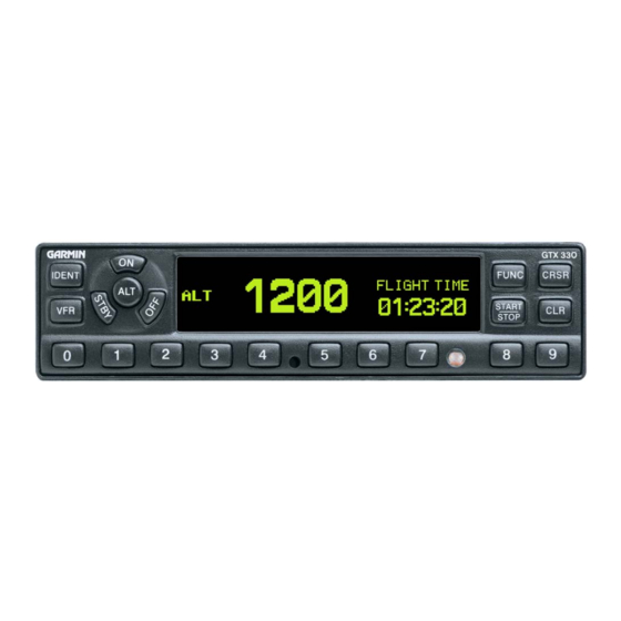
POST INSTALLATION CONFIGURATION AND CHECKOUT PROCEDURE Perhaps the most important factor in the GTX 330 transponder configuration and checkout is the Mode S address entry and Flight ID. Refer to Section 5.2.13.2 for Mode S address entry pages. CAUTION Be sure to check all aircraft control movements before flight is attempted to insure that the wiring harness does not touch any moving part. - Page 42 5.1.1 Function Selector Switches The function selection switches are: • OFF ⎯ Powers off the GTX 330. Pressing the STBY, ON or ALT key powers on the transponder displaying the last active identification code. • STBY ⎯ Selects the standby mode. When in standby mode, the transponder does not reply to any interrogations.
-
Page 43: Code Selection
STOP In Configuration mode, steps through functions in reverse. • CRSR ⎯ Initiates entry of the starting time for the Count Down timer and cancels transponder code entry. Selects changeable fields in Configuration mode. • CLR ⎯ Resets the Count Up, Count Down and Flight timers. Cancels the previous keypress during code selection and Count Down entry. - Page 44 5.1.3 Function Display PRESSURE ALT Displays the altitude data supplied to the GTX 330 in feet, hundreds of feet (i.e., flight level), or meters, depending on configuration. FLIGHT TIME Displays the Flight Time, controlled by the START/STOP key or by one of four airborne sources (squat switch, GPS ground speed recognition, airdata airspeed recognition or altitude increase) as configured during installation.
-
Page 45: Configuration
Configuration Pages NOTES The configuration descriptions given in this section reflect software version 6.00 or higher. Software version 4.01 or later is required for Mode S Enhanced Surveillance (EHS). When connecting the GTX 330 to a GNS 480 (CNX80) the transponder can be configured from either the GNS 480 (CNX80) or the GTX 330. - Page 46 5.2.1 Configuration Menu Page CONFIGURATION MENU CONFIGURATION MENU Page The JUMP TO menu page provides the capability to select a Configuration mode starting page without having to step through all of the pages. Press the CRSR key and sequence through to the desired selection with the 8 and 9 keys.
- Page 47 5.2.2 Audio Mode Pages AUDIO MODE (First) Page VOICE and VOLUME Select desired VOICE. The choice of OFF is not available for traffic (TIS) audio. Make sure the volume level is sufficient for AUDIO MODE (Second) Page the aircraft environment involved. MESSAGE Message is used as a test function only.
- Page 48 5.2.4 Display Mode Page DISPLAY MODE DISPLAY MODE Page SELECTION DESCRIPTION DEFAULT. Display automatically changes between Positive mode AUTO (Automatic) (during the day) and Negative mode (at night), depending on ambient light level received by the photocell. NGTV (Negative) Display always has light characters on a black background, regardless of ambient lighting.
- Page 49 MIN (Minimum) (Auto Only) Sets the minimum brightness of the display. The higher the number, the brighter the minimum brightness. Display minimum brightness has a range of 0 (zero) to 99, with the default set to 8. It is prudent to verify that display lighting characteristics match those of other equipment in the panel under night lighting conditions.
- Page 50 LVL (Level) Shows the current level of key lighting, based on the lighting input source (lighting bus voltage, or the ambient light if the source is PHOTO) and the settings on this configuration page. This field has a range of 0 (zero) to 999, but is not a user-entered field (display only). RSP TIME (Response Time) Sets the speed with which the brightness responds to ambient light changes (only for AUTO key lighting mode).
- Page 51 The same input data source cannot be selected for multiple input channels 1 through 3. ADLP is included for future use. For a connection to a Garmin GTS 820 or GTS 850, GARMIN TAS (HIGH) must be selected. Barometric data is not included in the GARMIN TAS format. A separate barometric data source is...
- Page 52 In aircraft having multiple traffic systems and multiple 400/500 Series units, configure ARINC 429 output CHANNEL 1 for GARMIN W/TIS and ARINC 429 output CHANNEL 2 for GARMIN. TIS is then enabled over CHANNEL 1.
- Page 53 The Garmin format is a data concentration function. The following data is sent out at specified intervals using high speed ARINC 429 (100 kHz). The transmit data labels and their rates are as follows: Label Data Rate Selected Course (degrees)
- Page 54 RS-232 serial air data from Shadin 9628XX-X family of Air Data Computers and Fuel/Air Data Computers plus altitude data. RS-232 serial input remote data. Receives GPS WAAS information the REMOTE Garmin GNS “ADSB DATA OUT” format. RS-232 OUTPUT (Altitude Source) SELECTION DESCRIPTION DEFAULT for channel 2.
- Page 55 FORMAT (Altitude Format) This field determines how the pressure altitude is shown on the GTX 330 display. SELECTION DESCRIPTION DEFAULT. The pressure altitude is displayed in hundreds of feet. For FLIGHT LVL example, a pressure altitude of 12,300 feet is displayed as “FL 123”. (Flight Level) Pressure altitude is displayed in feet.
- Page 56 5.2.12 Temperature Page SENSOR INSTALLED TEMPERATURE Page Sets the Sensor to YES or NO. Default is NO. UNITS Sets the units to degrees Fahrenheit or Centigrade. Default is degrees C. 5.2.13 Mode S Address Entry Pages NOTE It is VERY important to enter the Mode S address correctly in the GTX 330. When the unit is turned on for the first time, or an invalid address is recognized, the unit prompts the user to enter a valid aircraft address.
- Page 57 Press the CRSR key to select the next numeric entry field. Enter the next character as stated in the previous step, then move onto the next one, repeating the process until the complete number is entered. When finished, press the CRSR key to accept the number entry. Using the FUNC and/or START/STOP keys, toggle through the pages to get off of, then back onto the aircraft address page.
- Page 58 Using the FUNC and/or START/STOP keys, toggle through the pages to get off of, then back onto the aircraft address page. Verify that the address is correct. Turn the unit off. Power the unit back on in the normal mode. If the FLIGHT ID PWR-UP ENTRY page was selected verify that the unit requests the correct page during system turn on.
- Page 59 1E-3 being the worst and 1E-7 being the best rating. This data is used in ADS-B transmissions. Check with the GPS manufacturer for guidance on this setting. NOTE When installed with a Garmin 400/500 unit, the GPS INTEGRITY should be set to IE-5. GTX 330/GTX 330D Installation Manual Page 5-19...
- Page 60 DISABLE is the default. When ADS-B is set to DISABLE the BDS items listed in Section 1.6 that are marked “ES Enabled Units Only” are not active (no extended squitter). When ADS-B is set to PILOT SET ADS-B transmissions are active at power-on. Set to ENABLE when connecting to a Garmin GTS 8XX.
- Page 61 5.2.18 Gray Code Input Page GRAY CODE GRAY CODE INPUT Page This field shows the status (1 = ground, 0 = open) of each of the ten gray code altitude inputs. This information may aid in installation troubleshooting. This page is not used in systems that contain serial altitude input.
- Page 62 This field displays the input level from the outside air temperature sensor. UNIT TEMP This field displays the input level from the unit temperature sensor. 5.2.21 RS-232 Input Page RS-232 INPUT Page Depending on the selected inputs on Channel 1 and Channel 2 from the RS-232 Input page (ref para 5.2.10), this page displays the information received on the channel.
- Page 63 5.2.22 ARINC 429 Channels Pages ARINC 429 CHANNELS 1 and 2 The GTX 330 receives one of the following sets of ARINC 429 data on either ARINC 429 receivers #1, #2 or #3. The labels are chosen when selected in ARINC 429 INPUT, Section 5.2.9. The received data may be at either LOW or HIGH speed.
- Page 64 * If ADC W/ALT or EF/AD W/ALT format selected. GPS/FMS NAVIGATION SYSTEM (GPS) Label Data Selected Altitude (feet) Latitude (degrees) Longitude (degrees) Ground Speed (knots) Track Angle (degrees) GARMIN DISPLAY Label Data Selected Altitude (feet) Discrete Data Latitude (degrees) Longitude (degrees) Ground Speed (knots) Track Angle (degrees)
- Page 65 5.2.23 ARINC 743A Label Data Selected Altitude (feet) Track Angle (degrees) Latitude (degrees) Longitude (degrees) Ground Speed (knots) Horizontal Protection Level (feet) Vertical Protection Level (feet) Vertical Figure of Merit (feet) GPS Vertical Velocity (feet per minute) N/S Velocity (knots) E/W Velocity (knots) Horizontal Figure of Merit (feet) Ground Speed (knots)
-
Page 66: Enhanced Surveillance (Ehs)
It is the responsibility of the installing agency to determine whether the equipment that interfaces with the Garmin GTX 330 Mode S transponder actually provides the required output. Make sure the interfacing equipment outputs the correct parameter to the GTX 330 to meet Mode S EHS. See the vendor’s specification for configuring the external data sources for the data they are capable of providing. -
Page 67: Appendix Acertification Documents
APPENDIX A CERTIFICATION DOCUMENTS STC Permission Installers may reference the following STC as evidence of initial airworthiness. Installers are hereby granted permission to refer to this STC. It should be noted, however, this STC is a 'one-only' STC. GTX 330/GTX 330D Installation Manual Page A-1 190-00207-02 Revision R... -
Page 68: Continued Airworthiness
Continued Airworthiness Other than for regulatory periodic functional checks, maintenance of the GTX 330 is “on condition” only. Refer to the GTX 330 Maintenance Manual (Garmin P/N 190-00207-05). Periodic maintenance of the GTX 330 is not required. Refer to EASA ED Decision No 2003/19/RM, Annex II, Acceptable Means of Compliance to Part-145, Page 161. -
Page 69: Appendix Bassembly And Installation Drawings
APPENDIX B ASSEMBLY AND INSTALLATION DRAWINGS Figure B-1. GTX 330 Outline Drawing GTX 330/GTX 330D Installation Manual Page B-1 (Page B-2 blank) 190-00207-02 Revision R... - Page 70 APPENDIX B ASSEMBLY AND INSTALLATION DRAWINGS Figure B-2. GTX 330 Connector/Rack Assembly Drawing GTX 330/GTX 330D Installation Manual Page B-3 (Page B-4 blank) 190-00207-02 Revision R...
- Page 71 APPENDIX B ASSEMBLY AND INSTALLATION DRAWINGS Figure B-3. GTX 330 Recommended Panel Cutout Dimensions GTX 330/GTX 330D Installation Manual Page B-5 (Page B-6 blank) 190-00207-02 Revision R...
- Page 72 APPENDIX C INTERCONNECT DRAWINGS Figure C-1. GTX 330 to 400/500 Series Units, Typical Interconnect Wiring Diagram GTX 330/GTX 330D Installation Manual Page C-1 (Page C-2 blank) 190-00207-02 Revision R...
- Page 73 APPENDIX C INTERCONNECT DRAWINGS Figure C-2. GTX 330 to GNS 480 (CNX80), Typical Interconnect Wiring Diagram GTX 330/GTX 330D Installation Manual Page C-3 (Page C-4 blank) 190-00207-02 Revision R...
- Page 74 APPENDIX C INTERCONNECT DRAWINGS Figure C-3. GTX 330 to GNS 480 (CNX80) and MFD, Simplified Interconnect Wiring Diagram GTX 330/GTX 330D Installation Manual Page C-5 (Page C-6 blank) 190-00207-02 Revision R...
- Page 75 APPENDIX C INTERCONNECT DRAWINGS Figure C-4. GTX 330 Interconnect Wiring Diagram, Discrete and Audio Connections GTX 330/GTX 330D Installation Manual Page C-7 (Page C-8 blank) 190-00207-02 Revision R...
- Page 76 APPENDIX C INTERCONNECT DRAWINGS Figure C-5. GTX 330 Interconnect Wiring Diagram, Serial Devices Connections GTX 330/GTX 330D Installation Manual Page C-9 (Page C-10 blank) 190-00207-02 Revision R...
- Page 77 APPENDIX C INTERCONNECT DRAWINGS Figure C-6. GTX 330 Interconnect Wiring Diagram, Altitude and Temperature Connections GTX 330/GTX 330D Installation Manual Page C-11 (Page C-12 blank) 190-00207-02 Revision R...
- Page 78 APPENDIX C INTERCONNECT DRAWINGS Figure C-7. Dual Transponder Interconnect Wiring Diagram, Dual Display Connections (Sheet 1 of 2) GTX 330/GTX 330D Installation Manual Page C-13 (Page C-14 blank) 190-00207-02 Revision R...
- Page 79 APPENDIX C INTERCONNECT DRAWINGS Figure C-7. Dual Transponder Interconnect Wiring Diagram, Dual Display Connections (Sheet 2) GTX 330/GTX 330D Installation Manual Page C-15 (Page C-16 blank) 190-00207-02 Revision R...
- Page 80 APPENDIX C INTERCONNECT DRAWINGS Figure C-8. GTX 330 Interconnect Wiring Diagram, Aircraft with TIS and TCAD/TCAS GTX 330/GTX 330D Installation Manual Page C-17 (Page C-18 blank) 190-00207-02 Revision R...
- Page 81 APPENDIX C INTERCONNECT DRAWINGS Figure C-9. Dual TXP Interconnect Wiring Diagram, Encoding Altitude Connections (Sheet 1 of 3) GTX 330/GTX 330D Installation Manual Page C-19 (Page C-20 blank) 190-00207-02 Revision R...
- Page 82 APPENDIX C INTERCONNECT DRAWINGS Figure C-9. Dual TXP Interconnect Wiring Diagram, Encoding Altitude Connections (Sheet 2) GTX 330/GTX 330D Installation Manual Page C-21 (Page C-22 blank) 190-00207-02 Revision R...
- Page 83 APPENDIX C INTERCONNECT DRAWINGS Figure C-9. Dual TXP Interconnect Wiring Diagram, Encoding Altitude Connections (Sheet 3) GTX 330/GTX 330D Installation Manual Page C-23 (Page C-24 blank) 190-00207-02 Revision R...
- Page 84 APPENDIX C INTERCONNECT DRAWINGS Figure C-10. GTX 330 w/ES To GDL 90 Connections GTX 330/GTX 330D Installation Manual Page C-25 (Page C-26 blank) 190-00207-02 Revision R...
- Page 85 APPENDIX C INTERCONNECT DRAWINGS Figure C-11. GTX 330 to 400W/500W Series Units ADS-B Interconnect GTX 330/GTX 330D Installation Manual Page C-27 (Page C-28 blank) 190-00207-02 Revision R...
- Page 86 APPENDIX C INTERCONNECT DRAWINGS Figure C-12. GTX 330 to 400W/500W Series Units ADS-B TX Only Interconnect GTX 330/GTX 330D Installation Manual Page C-29 (Page C-30 blank) 190-00207-02 Revision R...