Garmin GTX 330 Installation Manual
Transponder
Hide thumbs
Also See for GTX 330:
- Installation manual (106 pages) ,
- System maintenance manual (56 pages) ,
- Pilot's manual (13 pages)

Related Manuals for Garmin GTX 330


Summary of Contents for Garmin GTX 330
- Page 1 330, GTX 330D TRANSPONDER INSTALLATION MANUAL Garmin Ltd. or its subsidiaries 190-00207-02 Revision G October 2004...
- Page 2 Garmin. Garmin hereby grants permission to download a single copy of this manual and of any revision to this manual onto a hard drive or other electronic...
- Page 3 NOTE Throughout this document references made to GTX 330 shall equally apply to the GTX 330D except where specifically noted. GTX 330 Installation Manual Page i...
- Page 4 This page intentionally left blank Page ii GTX 330 Installation Manual Revision G 190-00207-02...
-
Page 5: Table Of Contents
2.3 Installation Considerations ........................2-2 2.4 Antenna Installation...........................2-2 2.5 Cabling and Wiring..........................2-4 2.6 Installation Approval Considerations for Pressurized Aircraft ............2-5 2.7 Cooling Air ............................2-6 2.8 GTX 330 Installation .........................2-6 INSTALLATION PROCEDURE......................3-1 3.1 Unpacking Unit..........................3-1 3.2 Electrical Connections ........................3-1 3.3 Circuit Breaker Placard........................3-2 3.4 Post Installation Checkout .........................3-2... -
Page 6: Paragraph Page
5.2 Configuration Pages...........................5-5 APPENDIX A CERTIFICATION DOCUMENTS A.1 STC ..............................A-1 A.2 Continued Airworthiness ........................A-3 A.3 Environmental Qualification Forms, GTX 330 Mode S Transponder ........A-5 APPENDIX B ASSEMBLY AND INSTALLATION DRAWINGS APPENDIX C INTERCONNECT DRAWINGS Page iv GTX 330 Installation Manual... - Page 7 C-1 GTX 330 to 400/500 Series Units, Typical Interconnect Wiring Diagram ........C-1 C-2 GTX 330 to CNX80/ GNS 480, Typical Interconnect Wiring Diagram .......... C-3 C-3 GTX 330 to CNX80/GNS 480 and MFD, Simplified Interconnect Wiring Diagram ...... C-5 C-4 GTX 330 Interconnect Wiring Diagram, Discrete And Audio Connections ........C-7 C-5 GTX 330 Interconnect Wiring Diagram, Serial Devices Connections ..........
- Page 8 The table is current at the time of publication of this manual (see date on front cover) and is subject to change without notice. Authorized Garmin Sales and Service Centers are encouraged to access the most up-to-date bulletin and advisory information on the Garmin Dealer Resource web site at www.garmin.com using their Garmin-provided user name and...
-
Page 9: General Description
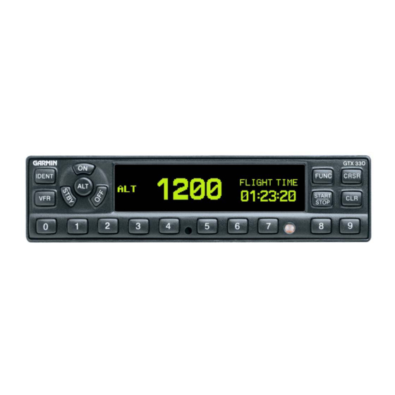
ARINC 429 output bus used by display systems such as the Garmin 400 Series/500 Series units. The GTX 330 is configured with all key controls. The layout of the front panel keys and displays segregates the transponder’s primary functions from the secondary functions. The unit can be configured so the aircraft avionics master bus can turn the unit on. -
Page 10: Tis System Capabilities
TIS provides a graphic display of traffic advisory information in the cockpit for non-TCAS equipped aircraft. Advisory traffic information is available to aircraft equipped with a Mode S data link such as the Garmin GTX 330 transponder. Advisory traffic information may be displayed on a Garmin 400/500 Series unit. -
Page 11: Interface Summary
Digitally recorded voice and discrete warning annunciator activated by Altitude Hold when limits are exceeded. • Diversity: GTX 330 is available with or without the diversity feature. The GTX 330 supports the following list of Binary Data Selector (BDS) registers: • BDS (0,0) Air Initiated Comm-B (AICB) •... -
Page 12: Technical Specifications
BDS register information is presented for the installation agency to understand the functionality of the GTX 330, and make a determination that the unit complies with the requirements of their civil aviation authorities. No further wiring or configuration programming is required for the unit. -
Page 13: Installation Approval
The article may be installed only if performed under 14 CFR Part 43 or the applicable airworthiness requirements. For GTX 330 TSO compliance and STC, see Appendix A. For antenna TSO compliance, refer to antenna manufacturer’s literature. -
Page 14: Limited Warranty
Garmin retains the exclusive right to repair or replace the unit or software or offer a full refund of the purchase price at its sole discretion. SUCH REMEDY SHALL BE YOUR SOLE AND EXCLUSIVE REMEDY FOR ANY BREACH OF WARRANTY. -
Page 15: Installation Overview
This section provides hardware equipment information for installing the GTX 330 Mode S Transponder, related hardware and optional accessories. Installation of the GTX 330 should follow the data detailed in this manual. Cabling is fabricated by the installing agency to fit each particular aircraft. The installation should follow the guidance of FAA AC 43.13-1B and AC 43.13-2A where applicable. -
Page 16: Installation Considerations
P/N 013-00066-00) can provide altitude data in either serial or parallel gray code format. Installation Considerations The GTX 330 can interface with equipment including altimeters, Air Data Computer (ADC) and a temperature probe. RS-232 and ARINC 429 provide a serial communication path between interfacing equipment. - Page 17 Figure 2-1. Antenna Installation Considerations A. The antenna(s) (Garmin P/N 010-10160-00) should be mounted away from major protrusions, such as engine(s), propeller(s), and antenna masts. It should also be as far as practical from landing gear doors, access doors, or other openings that could effect its radiation pattern.
-
Page 18: Cabling And Wiring
Qualified obsolete and Information Products List are shown for 5300 W. Franklin QPL-17. reference only; Drive replaced by Franklin, WI 53132 M17 type Tel: 800-327-9473 numbers. 414-421-5300 Fax: 414-421-5301 www.ecsdirect.com Page 2-4 GTX 330 Installation Manual Revision G 190-00207-02... -
Page 19: Installation Approval Considerations For Pressurized Aircraft
4. Obtain FAA Advisory Circular AC-183C and select (and contact) a DER from the roster of individuals identified thereunder. 5. Contact an aviation industry organization such as the Aircraft Electronics Association and request their assistance. GTX 330 Installation Manual Page 2-5 190-00207-02 Revision G... -
Page 20: Cooling Air
Cooling Air The GTX 330 meets all applicable TSO requirements without forced air cooling. The application of forced air cooling to the rear air nozzle of the GTX 330 is highly recommended to provide beneficial cooling to the unit. The GTX 330 was designed to handle a constant interrogation of 450 Pulse Repetition Frequency (PRF) per second, with short periods of 1200 PRF. - Page 21 4. Turn the Allen wrench clockwise until unit is secured in the rack. Continue turning until tight. Do not overtighten the screw. 5. To remove the unit from the rack, turn the 3/32” Allen wrench counterclockwise until it disengages from the rack. Figure 2-2. GTX 330 Unit Rack (115-00294-00) GTX 330 Installation Manual Page 2-7 190-00207-02...
- Page 22 This page intentionally left blank Page 2-8 GTX 330 Installation Manual Revision G 190-00207-02...
-
Page 23: Installation Procedure
D-subminiature connector (see Figure 4-1). The card-edge connector may be used to terminate shield grounds to the GTX 330 back plate. Table 4-1 lists the electrical connections of all input and output signals. See Appendix C for interconnect wiring diagrams and cable requirements for each signal. -
Page 24: Circuit Breaker Placard
NOTES 1. Non-Garmin part numbers shown are not maintained by Garmin and consequently are subject to change without notice. 2. Extracting the #16, #18 and #20 contact requires that the expanded wire barrel be cut off from the contact. It may also be necessary to push the pin out from the face of the connector when using an extractor due to the absence of the wire. -
Page 25: System Interconnects
ARINC 429 IN 3 A POWER GROUND ARINC 429 OUT 2 B ARINC 429 IN 3 B ARINC 429 OUT 2 A EXTERNAL SUPPRESSION I/O * Denotes Active Low (Ground to activate). GTX 330 Installation Manual Page 4-1 190-00207-02 Revision G... - Page 26 ARINC 429 IN 4 B ALTITUDE COMMON (GROUND) RESERVED RESERVED RESERVED RESERVED SPARE AIRCRAFT POWER 2 SPARE RESERVED SPARE AIRCRAFT POWER 2 SPARE SWITCHED POWER OUT * Denotes Active Low (Ground to activate). Page 4-2 GTX 330 Installation Manual Revision G 190-00207-02...
-
Page 27: Power And Lighting Function
4.2.2 Lighting Bus The GTX 330 unit can be configured to track a 28 Vdc, 14 Vdc, 5 Vdc or 5 Vac lighting bus using these inputs. The GTX 330 can also automatically adjust for ambient lighting conditions based on the photocell. -
Page 28: Altitude Functions
25-foot increments the GTX 330 must receive altitude from suitable altitude reporting devices through serial input connections. Altitude input to the GTX 330 received from parallel wire gray code encoders is supplied to the unit in 100-foot increments and thus reported in 100-foot increments. - Page 29 A dual GTX 330 installation can accept either parallel wire gray code altimeter input or RS-232 serial data input as shown in Figure 4-2. If transponder number 2 is a Garmin GTX 327, connect the RS-232 output from the altitude encoder to J3271 pin 19 (refer to GTX 327 Transponder Installation Manual, P/N 190-00187-02).
-
Page 30: Discrete Functions
4.4.4 Altimeter Selection Priority The installer must be aware of the GTX 330 priority for selecting encoded altimeter interconnections. The GTX 330 searches in this sequence for altitude, and stops when it finds a valid pressure altitude input. Only approved devices may provide altitude to the GTX 330 in accordance with 14 CFR Part 91.217. In addition, all altitude reporting devices installed in the aircraft must meet certification requirements of 14 CFR Part 91.413. - Page 31 When TIS CONNECT SELECT is inactive (“Standby” is displayed on the 400/500 Series units) the GTX 330 logs onto TIS service when a momentary ground is applied to P3301-46. When TIS is active, a momentary ground logs off of TIS service. Refer to Figures C-1, C-3, C-4, C-7 and C-8 for TIS CONNECT SELECT connections and to Sections 5.2.2, 5.2.3, 5.2.8 and 5.2.9 for TIS configuration.
-
Page 32: Serial Data Electrical Characteristics
ARINC 429 data concentrator. Since the Garmin 400/500 Series products have only two ARINC 429 input ports, the GTX 330 manages support for several equipment interfaces. The GTX 330 has four ARINC 429 input ports, making it capable of taking altitude, air data, heading, EFIS selected course and possible future features, and then concentrating it on the ARINC 429 OUT 2 port. - Page 33 TIS and TCAD/TCAS, both systems cannot be connected to the same 400/500 Series unit to display traffic simultaneously. In a multiple traffic system/multiple 400/500 Series unit installation, connect ARINC 429 CHANNEL 1 from the GTX 330 to only one of the 400/500 Series units and ARINC 429 CHANNEL 2 to the other 400/500 Series unit.
- Page 34 STANDBY SELECT (remote STANDBY)]. In installations having a transponder combination of GTX 330/GTX 327 (or GTX 330/other transponder), the GARMIN and GARMIN W/TIS formats from the ARINC 429 Output 1 port, J3301 pins 34 and 37, are available if the GTX 330 has SW 3.03 and above.
-
Page 35: Post Installation Configuration And Checkout Procedure
POST INSTALLATION CONFIGURATION AND CHECKOUT PROCEDURE Perhaps the most important factor in the GTX 330 transponder configuration and checkout is the Mode S address entry. Refer to Section 5.2.12 for Mode S address entry pages. CAUTION Be sure to check all aircraft control movements before flight is attempted to insure that the wiring harness does not touch any moving part. - Page 36 The function selection switches are: • OFF Powers off the GTX 330. Pressing the STBY, ON or ALT key powers on the transponder displaying the last active identification code. • STBY Selects the standby mode. When in standby mode, the transponder does not reply to any interrogations.
-
Page 37: Code Selection
Avoid selecting code 7500 and all codes in the 7600-7777 range. These codes trigger special indicators in automated facilities. An aircraft’s transponder code is used for ATC tracking purposes, therefore exercise care when making routine code changes. GTX 330 Installation Manual Page 5-3 190-00207-02... - Page 38 5.1.3 Function Display PRESSURE ALT Displays the altitude data supplied to the GTX 330 in feet, hundreds of feet (i.e., flight level), or meters, depending on configuration. FLIGHT TIME Displays the Flight Time, controlled by the START/STOP key or by one...
-
Page 39: Configuration
NOTES The configuration descriptions given in this section reflect software version 3.06. When connecting the GTX 330 to a CNX80/GNS 480 the transponder can be configured from either the CNX80/GNS 480 or the GTX 330. Although possible from the CNX80/GNS 480, configuration from the GTX 330 front panel offers more functions and easier to interpret displays. - Page 40 DESCRIPTION Jumps to Gray Code Input page. DIAGNOSTICS Jumps to Audio Volume page. DISPLAY/AUDIO Jumps to ARINC 429 INPUT #1 page. I/O CONFIG ACFT CONFIG Jumps to Operation Configuration #1 page. Page 5-6 GTX 330 Installation Manual Revision G 190-00207-02...
- Page 41 Enables/Disables Altitude Monitor sub page when altitude deviation is exceeded. 5.2.3 Traffic Information Page TRAFFIC MESSAGES TRAFFIC INFORMATION Page Sets the Traffic Messages to either Tone or Message. Traffic Information Service (TIS) provides notification of close proximity traffic. GTX 330 Installation Manual Page 5-7 190-00207-02 Revision G...
- Page 42 DISPLAY page does not appear to the pilot. MAN (Manual) Display backlighting is controlled manually by the pilot on the GTX 330 DISPLAY page. No backlight parameters can be entered when the manual mode is selected. LVL (Level) Shows the current level of display backlighting, based on the lighting input source (lighting bus voltage, or the ambient light if the source is PHOTO) and the settings on this configuration page.
- Page 43 SELECTION DESCRIPTION Key lighting is automatically controlled based on the parameters AUTO (Automatic) entered on this configuration page. Key lighting is controlled manually by the pilot on the GTX 330 MAN (Manual) DISPLAY page. GTX 330 Installation Manual Page 5-9...
- Page 44 PHOTO (Photocell) DEFAULT. Key lighting level is determined by the ambient light level as measured by the photocell on the GTX 330. Backlight level tracks a 14 volt DC aircraft lighting bus. Backlight level tracks a 28 volt DC aircraft lighting bus.
- Page 45 Display contrast is manually adjusted either here or by the pilot using MAN (Manual) the GTX 330 CONTRAST page. CONTRAST LEVEL ADJUSTMENT This is a “slider” bar graph control. Use the 8 key to move the graph to the left, decreasing the numbers and contrast level.
- Page 46 CHANNEL 1 for GARMIN W/TIS and ARINC 429 output CHANNEL 2 for GARMIN. TIS is then enabled over CHANNEL 1. The Garmin format is a data concentration function. The following data is sent out at specified intervals using high speed ARINC 429 (100 kHz). The transmit data labels and their rates are as follows:...
- Page 47 5.2.9 RS-232 Input and Output Page RS-232 INPUT (Altitude Source, GPS Data) RS-232 INPUT-OUTPUT Page This is the electrical source for the GTX 330 altitude and GPS data input. Refer to Section 4.4.4 for altimeter data selection priority. SELECTION DESCRIPTION DEFAULT.
- Page 48 VFR ID (VFR Transponder Code) This field is the four-digit code that is selected when the user presses the GTX 330 VFR key. In the United States, 1200 is the VFR code for any altitude. The default is set to 1200.
- Page 49 Mode S Address Entry Pages NOTE It is VERY important to enter the Mode S address correctly in the GTX 330. When the unit is turned on for the first time, or an invalid address is recognized, the unit prompts the user to enter a valid aircraft address.
- Page 50 FLIGHT ID PWR-UP ENTRY. When this choice is selected and the crew enters the Flight ID correctly, the flight number call sign for radio contact with ATC is the same flight identification that the GTX 330 Mode S transponder replies to ATC radar interrogations.
- Page 51 This field displays the state of the SQUAT SWITCH input. The box is filled when the SQUAT SWITCH input is active (the aircraft is on the ground as configured on the SETUP 2 page). GTX 330 Installation Manual Page 5-17...
- Page 52 If FADC or ADC is selected as an input, true or static air temperature (SAT), outside or total air temperature (TAT), indicated air speed (IAS), true air speed (TAS), density altitude (DALT), pressure altitude (PALT*), current barometric pressure (BARO) and vertical speed (VSPD) can be viewed. Page 5-18 GTX 330 Installation Manual Revision G 190-00207-02...
- Page 53 ARINC 429 Channels Pages ARINC 429 CHANNELS 1 and 2 The GTX 330 receives one of the following sets of ARINC 429 data on either ARINC 429 receivers #1, #2 or #3. The labels are chosen when selected in ARINC 429 INPUT, Section 5.2.8.
- Page 54 STATIC AIR TEMPERATURE (degrees) JOYSTICK LAT JOYSTICK LON TRUE HEADING MAGNETIC HEADING (degrees) GPS NAVIGATION SYSTEM (GPS) LABEL DATA GROUND SPEED (knots) * If ADC W/ALT or EF/AD W/ALT format selected. Page 5-20 GTX 330 Installation Manual Revision G 190-00207-02...
-
Page 55: Appendix Acertification Documents
(AFS) policy concerning follow-on field approvals of Traffic Alert/Advisory Systems, such as the Garmin GTX 330 Mode S and GTX 330D Diversity Mode S Transponder systems installed and operated under the provisions of 14 CFR Part 91 or Part 135. - Page 56 Page A-2 GTX 330 Installation Manual Revision G 190-00207-02...
-
Page 57: Continued Airworthiness
ICA. Following is a suggested ICA for a Garmin GTX 330 unit installation. Some of the checklist items do not apply, in which case they should be marked “N/A” (Not Applicable). - Page 58 Maintenance Instructions Maintenance of the GTX 330 is ‘on condition’ only. Periodic maintenance is not required. Refer to the GTX 330 Maintenance Manual. Troubleshooting Information Refer to the GTX 330 Maintenance Manual. Removal and Replacement Information Refer to Section 2 of this manual. If the unit is removed and reinstalled, a functional check of the equipment should be conducted in accordance with Section 5 of this manual.
-
Page 59: Environmental Qualification Forms, Gtx 330 Mode S Transponder
337, dated ______) along with a statement that the ICA is now part of the aircraft’s inspection/maintenance requirements. Environmental Qualification Forms, GTX 330 Mode S Transponder The following pages are copies of the Environmental Qualification Forms for the Garmin GTX 330 Transponder (005-00131-03) provided for reference only. GTX 330 Airborne ATCRBS/Mode S Transponder Equipment... - Page 60 Figure A-1. GTX 330 Environmental Qualification Form (Sheet 1 of 2) Page A-6 GTX 330 Installation Manual Revision G 190-00207-02...
- Page 61 Figure A-1. GTX 330 Environmental Qualification Form (Sheet 2 of 2) GTX 330 Installation Manual Page A- 190-00207-02 Revision G...
- Page 62 This page intentionally left blank Page A-8 GTX 330 Installation Manual Revision G 190-00207-02...