Packard Bell dot s series Service Manual
Hide thumbs
Also See for dot s series:
- User manual (107 pages) ,
- User manual (2279 pages) ,
- Quick start manual (23 pages)

Related Manuals for Packard Bell dot s series


Summary of Contents for Packard Bell dot s series
- Page 1 Packard Bell dot s Series Service Guide Service guide files and updates are available on the ACER/CSD web; for more information, please refer to http://csd.acer.com.tw PRINTED IN TAIWAN Downloaded from LpManual.com Manuals...
-
Page 2: Revision History
Revision History Please refer to the table below for the updates made to this service guide. Date Chapter Updates Downloaded from LpManual.com Manuals... - Page 3 Copyright Copyright © 2009 by Acer Incorporated. All rights reserved. No part of this publication may be reproduced, transmitted, transcribed, stored in a retrieval system, or translated into any language or computer language, in any form or by any means, electronic, mechanical, magnetic, optical, chemical, manual or otherwise, without the prior written permission of Acer Incorporated.
- Page 4 Conventions The following conventions are used in this manual: Denotes actual messages that appear SCREEN MESSAGES on screen. NOTE Gives bits and pieces of additional information related to the current topic. WARNING Alerts you to any damage that might result from doing or not doing specific actions.
- Page 5 Preface Before using this information and the product it supports, please read the following general information. This Service Guide provides you with all technical information relating to the BASIC CONFIGURATION decided for Acer's "global" product offering. To better fit local market requirements and enhance product competitiveness, your regional office MAY have decided to extend the functionality of a machine (e.g.
- Page 6 Downloaded from LpManual.com Manuals...
-
Page 7: Table Of Contents
Table of Contents System Specifications Features ............1 System Block Diagram . - Page 8 Table of Contents Removing the I/O Board ......... . .66 Removing the Mainboard .
- Page 9 Table of Contents USB Failure ........... .138 Wireless Function Failure .
- Page 10 Table of Contents Downloaded from LpManual.com Manuals...
-
Page 11: System Specifications
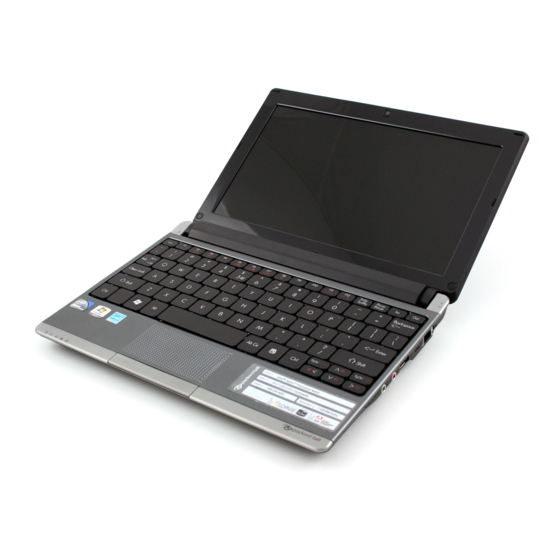
Chapter 1 System Specifications Features Below is a brief summary of the computer’s many features: Operating System ® Genuine Windows 7 Starter for Small Notebook PCs • ® Genuine Windows 7 Home Basic (China only) • Platform ® ™ Intel Atom processor N450 (512 KB L2 cache, 1.66 GHz, DDR2 667 MHz) •... -
Page 12: Dimensions And Weight
I/O Interface Multi-in-1 card reader • Three USB 2.0 ports • External display (VGA) port • Headphone/speaker/line-out jack • Microphone-in jack • Ethernet (RJ-45) port • DC-in jack for AC adapter • Dimensions and Weight 258.5 (W) x 185 (D) x 25.2 (H) mm (10.17 x 7.28 x 0.99 inches) •... -
Page 13: Special Keys And Controls
Special keys and controls 84-key keyboard, 93% of standard-size keyboard • Multi-gesture touchpad, supporting two-finger scroll, pinch, rotate, flip • ® 12 function keys, four cursor keys, one Windows key, hotkey controls, embedded numeric • keypad, international language support Power button with LED •... -
Page 14: System Block Diagram
System Block Diagram Chapter 1 Downloaded from LpManual.com Manuals... -
Page 15: Front View
Front View Component Icon Description Status Indicators Light-Emitting Diodes (LED) that light up to show the status of the computer's functions and components. Left View Component Icon Description DC-in jack Connects to an AC adapter. External display Connects to a display device (e.g., external monitor, LCD (VGA) port projector). -
Page 16: Bottom And Rear View
Component Icon Description Kensington lock Connects to a Kensington-compatible computer security lock. slot Ethernet (RJ-45) Connects to an Ethernet 10/100-based network. port Bottom and Rear View Component Icon Description Battery bay Houses the computer's battery pack. Note: The battery shown is for reference only. Your PC may have a different battery, depending on the model purchased. -
Page 17: Keyboard Area And Lcd Panel
Keyboard Area and LCD Panel Component Icon Description Webcam Web camera for video communication Microphone Internal microphone for sound recording. Display screen Also called Liquid-Crystal Display (LCD), displays computer output. Power button/ Indicates when the computer is turned on. indicator Keyboard Provides all the features of a full-sized, computer keyboard. - Page 18 Component Icon Description Bluetooth Indicates the status of the Bluetooth communication. communication (only for certain models) indicator 3G/ Indicates the status of 3G/Wireless LAN communication: Wireless LAN Blue light on — 3G on / WiFi on or off • communication Orange light on —...
-
Page 19: Touchpad Basics
Touchpad Basics The following items show you how to use the TouchPad: • Move your finger across the TouchPad (1) to move the cursor. • Press the left (2) and right (3) buttons located beneath the TouchPad to perform selection and execution functions. -
Page 20: Using The Keyboard
Using the Keyboard Your Packard Bell Dot S has a close-to-full-sized keyboard and an embedded numeric keypad, separate cursor, lock, function and special keys. Lock Keys and Embedded Numeric Keypad The keyboard has three lock keys which you can toggle on and off. -
Page 21: Windows Keys
Windows Keys The keyboard has two keys that perform Windows-specific functions. Description Windows key Pressed alone, this key has the same effect as clicking on the Windows Start button; it launches the Start menu. It can also be used with other keys to provide a variety of functions: <... -
Page 22: System Keys
System Keys The computer employs hotkeys or key combinations to access most of the computer’s controls like screen brightness, Bluetooth and WiFi. To activate hot keys, press and hold the <Fn> key before pressing the other key in the hotkey combination. Function Key Description <Fn>... -
Page 23: Hot Keys
Hot Keys The computer employs hotkeys or key combinations to access most of the computer's controls like screen brightness and volume output. To activate hotkeys, press and hold the <Fn> key before pressing the other key in the hotkey combination. Hotkey Icon Function... -
Page 24: Special Key
Special Key You can locate the Euro symbol and the US dollar sign at the upper-center and/or bottom-right of your keyboard. The Euro symbol Open a text editor or word processor. Hold <Alt Gr> and then press the <5> key at the upper-center of the keyboard. NOTE: Some fonts and software do not support the Euro symbol. -
Page 25: Hardware Specifications And Configurations
Hardware Specifications and Configurations Processor Item Specification Intel® Pineview-M (N450, N470) Processor • Micro-FCBGA8 packaging technologies • On die 512-kB, 8-way L2 cache • Core Logic AMD M880G Chipset • Processor Specifications Mfg. cache Item Cores Package Power Acer P/N Speed Tech Size... - Page 26 Item Specification Supports 60 Hz External resolution - VGA port up to 1600 x 900: 16.7 • million colors Resolution • LAN Interface Item Specification Atheros AR8132L LAN Chipset for 10/100LAN LAN connector type RJ-45 LAN connector location Right side Features Support for 10/100 Hard Disk Drive Interface...
- Page 27 Battery Specification Item 3 Cell 6 Cell 2.2 6 Cell 2.8 Vendor & model name SIMPLO UM09G75 SIMPLO UM09H75 SIMPLO UM09H70 Battery Type Li-ion Li-ion Li-ion Pack capacity 2200 mAh 4400 mAh 5600 mAh Normal Voltage 11.1V 11.1V 11.1 Charge Voltage 12.6V 12.6V 12.6...
- Page 28 Chapter 1 Downloaded from LpManual.com Manuals...
-
Page 29: System Utilities
Chapter 2 System Utilities BIOS Setup Utility The BIOS Setup Utility is a hardware configuration program built into your computer’s BIOS (Basic Input/ Output System). Your computer is already properly configured and optimized, and you do not need to run this utility. However, if you encounter configuration problems, you may need to run Setup. -
Page 30: Information
Information The Information screen displays a summary of your computer hardware information. I n s y d e H 2 0 S e t u p U t i l i t y R e v . 3 . 5 Information Main Security... -
Page 31: Main
Main The Main screen allows the user to set the system time and date as well as enable and disable boot option and recovery. I n s y d e H 2 0 S e t u p U t i l i t y R e v . -
Page 32: Security
Security The Security screen contains parameters that help safeguard and protect your computer from unauthorized use. I n s y d e H 2 0 S e t u p U t i l i t y R e v . 3 . 5 Information Main Security... -
Page 33: Setting A Password
Setting a Password Follow these steps as you set the user or the supervisor password: Use the ↑ and ↓ keys to highlight the Set Supervisor Password parameter and press the Enter key. The Set Supervisor Password box appears: S e t S u p e r v i s o r P a s s w o r d E n t e r N e w P a s s w o r d C o n f i r m N e w P a s s w o r d Type a password in the “Enter New Password”... -
Page 34: Changing A Password
Changing a Password Use the ↑ and ↓ keys to highlight the Set Supervisor Password parameter and press the Enter key. The Set Password box appears. S e t S u p e r v i s o r P a s s w o r d E n t e r C u r r e n t P a s s w o r d E n t e r N e w P a s s w o r d C o n f i r m N e w P a s s w o r d... -
Page 35: Boot
Boot This menu allows the user to decide the order of boot devices to load the operating system. Bootable devices includes the USB diskette drives, the onboard hard disk drive and the DVD drive in the module bay. I n s y d e H 2 0 S e t u p U t i l i t y R e v . -
Page 36: Exit
Exit The Exit screen allows you to save or discard any changes you made and quit the BIOS Utility. I n s y d e H 2 0 S e t u p U t i l i t y R e v . -
Page 37: Bios Flash Utility
BIOS Flash Utility The BIOS flash memory update is required for the following conditions: • New versions of system programs • New features or options • Restore a BIOS when it becomes corrupted. Use the Phlash utility to update the system BIOS flash ROM. NOTE: If you do not have a crisis recovery diskette at hand, then you should create a Crisis Recovery Diskette before you use the Phlash utility. -
Page 38: Dos Flash Utility
DOS Flash Utility Perform the following steps to use the DOS Flash Utility: Press F2 during boot to enter the Setup Menu. Select Boot Menu to modify the boot priority order, for example, if using USB HDD to Update BIOS, move USB HDD to position 1. - Page 39 NOTE: If the AC power is not connected, the following message displays. Plug in the AC power to continue. Flash is complete when the message Flash programming complete displays. Chapter 2 Downloaded from LpManual.com Manuals...
-
Page 40: Winflash Utility
WinFlash Utility Perform the following steps to use the WinFlash Utility: Double click the WinFlash executable. Click OK to begin the update. A progress screen displays. When the process is complete, close all programs and applications and reboot the system. Chapter 2 Downloaded from LpManual.com Manuals... -
Page 41: Remove Hdd/Bios Password Utilities
Remove HDD/BIOS Password Utilities This section provides you with details about removing HDD/BIOS password methods: Removing HDD Password: If you key in the wrong HDD password three times, an error is generated. To reset the HDD password, perform the following steps: After the error is displayed, select the Enter Unlock Password option on the screen. - Page 42 Removing BIOS Passwords: To clear the User or Supervisor passwords, open the RAM door and use a metal instrument to short the U72 jumper as shown below. Cleaning BIOS Passwords To clean the User or Supervisor passwords, perform the following steps: From a DOS prompt, execute clnpwd.exe Press 1 or 2 to clean the desired password shown on the screen.
-
Page 43: Miscellaneous Utilities
Miscellaneous Utilities Using Boot Sequence Selector Boot Sequence Selector allows the boot order to be changes without accessing the BIOS. To use Boot Sequence Selector, perform the following steps: Enter into DOS. Execute BS.exe to display the usage screen. Select the desired boot sequence by entering the corresponding sequence, for example, enter BS2 to change the boot sequence to HDD|CD ROM|LAN|Floppy. - Page 44 Example 1: Read DMI Information from Memory Input: dmitools /r Output: Manufacturer (Type1, Offset04h): Acer Product Name (Type1, Offset05h): Aspire one xxxxx Serial Number (Type1, Offset07h): 01234567890123456789 UUID String (Type1, Offset08h): xxxxxxxx-xxxx-xxxx-xxxx-xxxxxxxxxxxx Asset Tag (Type3, Offset04h): Acer Asstag Example 2: Write Product Name to EEPROM Input: dmitools /wp Acer Example 3: Write Serial Number to EEPROM...
- Page 45 Execute MAC.BAT to write MAC information to eeprom. Chapter 2 Downloaded from LpManual.com Manuals...
- Page 46 Chapter 2 Downloaded from LpManual.com Manuals...
-
Page 47: Machine Disassembly And Replacement
Chapter 3 Machine Disassembly and Replacement IMPORTANT:The outside housing and color may vary from the mass produced model. This chapter contains step-by-step procedures on how to disassemble the notebook computer for maintenance and troubleshooting. Disassembly Requirements To disassemble the computer, you need the following tools: Wrist grounding strap and conductive mat for preventing electrostatic discharge •... -
Page 48: General Information
General Information Pre-disassembly Instructions Before proceeding with the disassembly procedure, make sure that you do the following: 1. Turn off the power to the system and all peripherals. 2. Unplug the AC adapter and all power and signal cables from the system. 3. -
Page 49: External Module Disassembly Process
External Module Disassembly Process IMPORTANT:The outside housing and color may vary from the mass produced model. External Modules Disassembly Flowchart The flowchart below gives you a graphic representation on the entire disassembly sequence and instructs you on the components that need to be removed during servicing. For example, if you want to remove the main board, you must first remove the keyboard, then disassemble the inside assembly frame in that order. -
Page 50: Removing The Battery Pack
Removing the Battery Pack 1. Turn computer over. Slide the battery lock in the direction shown. 2. Slide and hold the battery release latch to the release position (1), then lift out the battery pack from the main unit (2). Chapter 3 Downloaded from LpManual.com Manuals... -
Page 51: Removing The Sd Dummy Card
Removing the SD Dummy Card 1. Push the SD dummy card inwards to eject it. 2. Pull the card out from the slot. Chapter 3 Downloaded from LpManual.com Manuals... -
Page 52: Removing The Dimm Module
Removing the DIMM Module 1. Remove the one (1) captive screws of the RAM cover. 2. Lift off the RAM cover. 3. Push out the release latches on both sides of the DIMM socket to release the DIMM module. Chapter 3 Downloaded from LpManual.com Manuals... - Page 53 4. Remove the DIMM module. Chapter 3 Downloaded from LpManual.com Manuals...
-
Page 54: Removing The Hdd Module
Removing the HDD Module 1. See “Removing the Battery Pack” on page 40. 2. Loosen the three (3) captive screws on the HDD cover. 3. Pry up the HDD cover at the location shown and remove. 4. Lift out the pull-tab. Chapter 3 Downloaded from LpManual.com Manuals... - Page 55 5. Grasp the pull-tab and pull the HDD module out of the bay. 6. Remove the HDD module. 7. Remove the four (4) screws (two each side) securing the hard disk to the carrier. Step Size Quantity Screw Type HDD Carrier M3*3 Chapter 3 Downloaded from LpManual.com Manuals...
- Page 56 8. Remove the HDD from the carrier. Chapter 3 Downloaded from LpManual.com Manuals...
-
Page 57: Removing The Wlan Module
Removing the WLAN Module 1. See “Removing the Battery Pack” on page 40. 2. Loosen the three (3) captive screws on the HDD cover. 3. Pry up the HDD cover at the location shown and remove. 4. Disconnect the antenna cables from the WLAN Module. NOTE: Cable placement is Black to the MAIN terminal (top) and White to the AUX terminal (bottom). - Page 58 5. Move the antennas away and remove the one (1) screw. Step Size Quantity Screw Type WLAN Module M2*3 6. Remove the WLAN Module from the WLAN socket. NOTE: When reattaching the antennas, ensure the cables are tucked into the chassis to prevent damage. Chapter 3 Downloaded from LpManual.com Manuals...
-
Page 59: Removing The 3G Module
Removing the 3G Module 1. See “Removing the Battery Pack” on page 40. 2. Loosen the three (3) captive screws on the HDD cover. 3. Pry up the HDD cover and remove. 4. Disconnect the antenna cables from the3G module. NOTE: Cable placement is BLUE to the MAIN terminal (bottom) and White to the AUX terminal (top). - Page 60 5. Move the antennas away and remove the one (1) screw. Step Size Quantity Screw Type 3G Module M2*3 6. Remove the 3G Module from the 3G socket. When reattaching the antennas, ensure the cables are tucked into the chassis to prevent damage. Chapter 3 Downloaded from LpManual.com Manuals...
-
Page 61: Main Unit Disassembly Process
Main Unit Disassembly Process Main Unit Disassembly Flowchart Remove External Modules before proceeding Remove Keyboard Remove Remove Upper Cover Button Board Remove Remove Remove Remove Remove Power Board LED Board Bluetooth Module Bridge Board Function Board Remove Remove Remove Thermal Module Mainboard I/OBoard Remove... -
Page 62: Removing The Keyboard
Removing the Keyboard 1. Push down on the latch holding the top center of the keyboard. 2. Pry up the keyboard at the top center. 3. Lift up the left and right corners of the keyboard forcefully to release latches under the board. Chapter 3 Downloaded from LpManual.com Manuals... - Page 63 4. Turn the keyboard over. 5. Unlock the FPC. 6. Remove the FPC and the keyboard. Chapter 3 Downloaded from LpManual.com Manuals...
-
Page 64: Removing The Upper Cover
Removing the Upper Cover 1. See “Removing the Keyboard” on page 52. 2. Unlock and remove the power FFC. 3. Unlock and remove the buttonboard FFC. 4. Remove the seven (7) screws in the upper cover. Step Size Quantity Screw Type Upper Cover M2*8 Chapter 3... - Page 65 5. Turn the computer over. Detach the antenna cables from the retention guides. 6. Remove the eleven (11) screws in the lower cover. Step Size Quantity Screw Type Lower Cover M2*8 (red call out) M2x3 (green call out) M2x4 (purple call out) Chapter 3 Downloaded from LpManual.com Manuals...
- Page 66 7. Open the LCD module, stand the LCD module vertically, then pry the upper cover away from the lower cover at the location shown. 8. Continue to pry the covers apart long the front edge. 9. Pry apart the upper cover along the sides. Chapter 3 Downloaded from LpManual.com Manuals...
- Page 67 10. Firmly pull the upper cover up off the latches underneath the cover. 11. Remove the upper cover. Chapter 3 Downloaded from LpManual.com Manuals...
-
Page 68: Removing The Button Board
Removing the Button Board 1. See “Removing the Upper Cover” on page 54. 2. Remove the tape from the touchpad FFC. 3. Release the touchpad FFC locking latch and disconnect the touchPad FFC from the cover. 4. Pull the button board FFC off the adhesive. Chapter 3 Downloaded from LpManual.com Manuals... - Page 69 5. Remove the two (2) screws securing the TouchPad Bracket to the Upper Cover. Step Size Quantity Screw Type Button Board M2*3 6. Remove the button board from the Upper Cover. Chapter 3 Downloaded from LpManual.com Manuals...
-
Page 70: Removing The Power Board
Removing the Power Board 1. See “Removing the Upper Cover” on page 54. 2. Pry the power board off the adhesive and remove. Chapter 3 Downloaded from LpManual.com Manuals... -
Page 71: Removing The Led Board
Removing the LED Board 1. See “Removing the Upper Cover” on page 54. 2. Unlock and remove the LED FFC from the mainboard. 3. Remove the one (1) screw. Step Size Quantity Screw Type LED Board M2*3 4. Lift the LED Board away from the chassis. Chapter 3 Downloaded from LpManual.com Manuals... -
Page 72: Removing The Function Board
Removing the Function Board 1. See “Removing the Upper Cover” on page 54. 2. Remove the tape over the cables. 3. Disconnect the microphone cable. 4. Unlock and disconnect the function board FFC. Chapter 3 Downloaded from LpManual.com Manuals... - Page 73 5. Pry up the function board and remove. Chapter 3 Downloaded from LpManual.com Manuals...
-
Page 74: Removing The Bluetooth Module
Removing the Bluetooth Module 1. See “Removing the Upper Cover” on page 54. 2. Disconnect the Bluetooth cable from the mainboard connector. 3. Pry the Bluetooth module off the adhesive. 4. Disconnect the cable from the Bluetooth module. Chapter 3 Downloaded from LpManual.com Manuals... -
Page 75: Removing The Bridge Board
Removing the Bridge Board 1. See “Removing the Upper Cover” on page 54. 2. Remove the tape over the cables. 3. Remove the two (2) screws. Step Size Quantity Screw Type Bridge Board M2*3 4. Remove the bridge board from the chassis. Chapter 3 Downloaded from LpManual.com Manuals... -
Page 76: Removing The I/O Board
Removing the I/O Board 1. See “Removing the Upper Cover” on page 54. 2. See “Removing the Function Board” on page 62. 3. See “Removing the Bridge Board” on page 65. 4. Disconnect the speaker cable. 5. Remove the one (1) screw. Step Size Quantity... - Page 77 6. Remove the I/O board from the chassis. Chapter 3 Downloaded from LpManual.com Manuals...
-
Page 78: Removing The Mainboard
Removing the Mainboard 1. See “Removing the Power Board” on page 60. 2. See “Removing the LED Board” on page 61. 3. See “Removing the Function Board” on page 62. 4. See “Removing the Bluetooth Module” on page 64. 5. See “Removing the Bridge Board” on page 65. 6. -
Page 79: Removing The Thermal Module
9. Remove the one (1) screw. Step Size Quantity Screw Type Mainboard M2*3 Removing the Thermal Module 1. See “Removing the Mainboard” on page 68. 2. Disconnect the fan cable. Chapter 3 Downloaded from LpManual.com Manuals... - Page 80 3. Remove the three (3) screws. Step Size Quantity Screw Type Thermal Module M2*3 4. Remove the thermal module from the mainboard. Chapter 3 Downloaded from LpManual.com Manuals...
-
Page 81: Removing The Lcd Module
Removing the LCD Module 1. See “Removing the Mainboard” on page 68. 2. Remove the DC jack housing. 3. Lift up the chassis and pull the left antenna cables through to the front. 4. Remove the adhesive tape from the antenna cables. Chapter 3 Downloaded from LpManual.com Manuals... - Page 82 5. Remove the left antenna cables from the retention guides. 6. Remove the right antenna cables from the antenna guides. 7. Remove the two (2) screws. Step Size Quantity Screw Type LCD Module M2*4 Chapter 3 Downloaded from LpManual.com Manuals...
-
Page 83: Removing The Speaker Module
8. Remove the LCD module from the chassis. Removing the Speaker Module 1. See “Removing the I/O Board” on page 66. 2. See “Removing the Mainboard” on page 68. 3. Remove the four (4) screws. Step Size Quantity Screw Type Speakers M2*3 Chapter 3... - Page 84 4. Remove the adhesive tape off the speaker cables. 5. Remove the cables from the retention guides and pull away. Chapter 3 Downloaded from LpManual.com Manuals...
-
Page 85: Lcd Module Disassembly Process
LCD Module Disassembly Process LCD Module Disassembly Flowchart Remove LCD Panel from Main Unit before proceeding Remove LCD Bezel Remove Camera Module Remove LCD Panel Remove Remove Remove Remove LCD Cable LCD Brackets 3G Antennas Microphone Remove WLAN Antennas Screw List Step Screw Quantity... -
Page 86: Removing The Lcd Bezel
Removing the LCD Bezel 1. See “Removing the LCD Module” on page 71. 2. Remove the two (2) screw caps. 3. Remove the two (2) screws. Step Size Quantity Screw Type LCD Bezel M2*4 Ni 4. Starting from the bottom center of the bezel, pry the bezel upwards and away from the panel. Move along the edge and down each side until all sides of the bezel are removed. - Page 87 Chapter 3 Downloaded from LpManual.com Manuals...
-
Page 88: Removing The Camera Module
Removing the Camera Module 1. See “Removing the LCD Bezel” on page 76. 2. Disconnect the camera cable. 3. Pry the camera from the module. Chapter 3 Downloaded from LpManual.com Manuals... -
Page 89: Removing The Lcd Panel
Removing the LCD Panel 1. See “Removing the Camera Module” on page 78. 2. Lift the foil off the LCD cable. 3. Remove the four (4) securing screws from the LCD Panel. Step Size Quantity Screw Type LCD Panel M2*3 4. -
Page 90: Removing The Lcd Brackets And Cable
Removing the LCD Brackets and Cable 1. See “Removing the LCD Panel” on page 79. 2. Remove the four (4) screws of the LCD brackets. Step Size Quantity Screw Type LED Panel M2*3 Brackets 3. Turn the LCD panel over to expose the rear. Lift the cable as shown to disengage the adhesive strip securing it in place. - Page 91 5. Disconnect the cable from the panel connector and lift the FPC cable from the panel. Chapter 3 Downloaded from LpManual.com Manuals...
-
Page 92: Removing The Microphone Module
Removing the Microphone Module 1. See “Removing the LCD Panel” on page 79. 2. Lift the foil tabs off the microphone cable. 3. Lift the foil tab off the micrphone module. 4. Lift the microphone module clear of the module. Chapter 3 Downloaded from LpManual.com Manuals... -
Page 93: Removing The 3G Antennas
Removing the 3G Antennas 1. See “Removing the LCD Panel” on page 79. 2. Lift the foil tabs off the 3G right cable. 3. Lift the right 3G antenna cable out of the retention guides. Chapter 3 Downloaded from LpManual.com Manuals... - Page 94 4. Pry the right 3G antenna off the LCD module cover. 5. Lift the right antenna foil off the adhesive backing. 6. Lift the foil tab off the left 3G antenna cable. Chapter 3 Downloaded from LpManual.com Manuals...
-
Page 95: Removing The Wlan Antennas
7. Pull the left 3G antenna cable out of the retention guides. 8. Pry the left 3G antenna off the LCD module cover. Removing the WLAN Antennas 1. See “Removing the 3G Antennas” on page 83. 2. Remove the right WLAN antenna cable from the cable retention guides. Chapter 3 Downloaded from LpManual.com Manuals... - Page 96 3. Pry the right WLAN antenna off the LCD module cover. 4. Remove the left WLAN antenna cable away from the retention guides. 5. Pry the WLAN antenna off the LCD module cover. Chapter 3 Downloaded from LpManual.com Manuals...
-
Page 97: Lcd Module Reassembly Procedure
LCD Module Reassembly Procedure Replacing the WLAN Antennas 1. Replace the left (white cable) and right (black cable) antennas as shown. Press down on the adhesive pads to secure the antennas in place. 2. Lay the cables along the cable channel. Chapter 3 Downloaded from LpManual.com Manuals... -
Page 98: Replacing The 3G Antennas
Replacing the 3G Antennas 1. Adhere the left 3G antenna (blue cable) onto the LCD module cover. 2. Lay the cable through the cable channel guides. 3. Replace the foil tabs over the cables. Chapter 3 Downloaded from LpManual.com Manuals... - Page 99 4. Adhere the right side 3G antenna (yellow cable) to the LCD module case. 5. Lay the cable through the cable channel guides. 6. Replace the foil tabs over the cables. Chapter 3 Downloaded from LpManual.com Manuals...
-
Page 100: Replacing The Microphone
Replacing the Microphone 1. Adhere the microphone into the LCD module cover. 2. Replace the foil tab over the microphone. 3. Lay the microphone cable onto the LCD module cover. Chapter 3 Downloaded from LpManual.com Manuals... - Page 101 4. Replace the foil tabs. Chapter 3 Downloaded from LpManual.com Manuals...
-
Page 102: Replacing The Lcd Cable
Replacing the LCD Cable 1. Replace the LCD cable connector. 2. Adhere the transparent connector protector. 3. Adhere the LCD cable to LCD panel bottom side edge as shown. NOTE: The circular portion of the cable runs along the panel side. The flat portion of the cable is adhered to the panel base. -
Page 103: Replacing The Lcd Panel
4. Adhere the webcam LCD cable arm to the LCD panel. NOTE: Pay attention to the proper location of the webcam cable arm. Replacing the LCD Panel 1. Align the left and right LCD panel brackets with the panel. 2. Replace the four (4) screws. Chapter 3 Downloaded from LpManual.com Manuals... - Page 104 Step Size Quantity Screw Type LCD Module M2*3 Brackets 3. Replace the LCD panel into the LCD module cover bottom edge first. 4. Replace the four (4) screws. Chapter 3 Downloaded from LpManual.com Manuals...
-
Page 105: Replacing The Camera Module
Step Size Quantity Screw Type LCD Module M2*3 Brackets 5. Adhere the LCD cable along the panel edge. 6. Lay the cables though the left and right hinges as shown. Replacing the Camera Module 1. Adhere the camera to the LCD module cover. Chapter 3 Downloaded from LpManual.com Manuals... - Page 106 2. Connect the webcam cable. Chapter 3 Downloaded from LpManual.com Manuals...
-
Page 107: Replacing The Lcd Bezel
Replacing the LCD Bezel 1. Locate the bezel hinges first and press down until there are no gaps between the bezel and the LCD module cover hinge wells. IMPORTANT: Ensure that the LCD cables pass through the hinge wells and are not trapped by the bezel. 2. - Page 108 3. Replace the two (2) screws. Step Size Quantity Screw Type LCD Bezel M2*4 Ni 4. Replace the two (2) screw covers. Chapter 3 Downloaded from LpManual.com Manuals...
-
Page 109: Main Module Reassembly Procedure
Main Module Reassembly Procedure Replacing the Speakers 1. Replace the two speaker housings into the bottom cover. 2. Lay the speaker cables into the retention guides. 3. Replace the adhesive tape. Chapter 3 Downloaded from LpManual.com Manuals... -
Page 110: Replacing The Lcd Module
4. Replace the four (4) screws. Step Size Quantity Screw Type Speakers M2*3 Replacing the LCD Module 1. Place the LCD module onto the main unit lower cover. Chapter 3 Downloaded from LpManual.com Manuals... - Page 111 2. Replace the two (2) screws. Step Size Quantity Screw Type LCD Hinges M2*4 3. Lay the right side cables into the retention guides. 4. Lay the left side cables into the retention guides. Chapter 3 Downloaded from LpManual.com Manuals...
-
Page 112: Replacing The Thermal Module
5. Replace the adhesive tape. 6. Push the left side cables through the slot in the lower cover. 7. Replace the DC power jack. Replacing the Thermal Module IMPORTANT:Apply a suitable thermal grease and ensure all heat pads are in place before replacing the Thermal Module. - Page 113 ShinEtsu 7762 • The following thermal pads are approved for use: 1. Eapus XR-PERemove all traces of thermal grease from the CPU using a lint-free cloth or cotton swab and Isopropyl Alcohol, Acetone, or other approved cleaning agent. 2. Apply a small amount of thermal grease to the centre of the CPU—there is no need to spread the grease manually, the force used during the installation of the Thermal Module is sufficient.
- Page 114 Chapter 3 Downloaded from LpManual.com Manuals...
-
Page 115: Replacing The Mainboard
Replacing the Mainboard 1. Ensure that the Mainboard is face up (the CPU is not visible). Place the Mainboard in the chassis, left side first (1), then rotate it downward into position (2). 2. Replace the one (1) screw in the mainboard. Step Size Quantity... - Page 116 4. Connect the LCD cable. 5. Replace the adhesive tape over the LCD cable. Chapter 3 Downloaded from LpManual.com Manuals...
-
Page 117: Replacing The I/O Board
Replacing the I/O Board 1. Replace the I/O board, inserting the external connectors first 1, then lowering the board into place 2. 2. Replace the one (1) screw. Step Size Quantity Screw Type I/O Board M2*3 3. Connect the speaker cable. Chapter 3 Downloaded from LpManual.com Manuals... -
Page 118: Replacing The Bridge Board
Replacing the Bridge Board 1. Replace the bridge board, firmly seating the pcb in the underside connectors. 2. Replace the two (2) screws. Step Size Quantity Screw Type Bridge Board M2*3 3. Replace the adhesive tape over the speaker cable. Chapter 3 Downloaded from LpManual.com Manuals... -
Page 119: Replacing The Bluetooth Module
Replacing the Bluetooth Module 1. Connect the Bluetooth cable to the Bluetooth module 2. Replace the Bluetooth module. 3. Connect the Bluetooth cable to the mainboard. Chapter 3 Downloaded from LpManual.com Manuals... -
Page 120: Replacing The Function Board
Replacing the Function Board 1. Replace the function board. 2. Connect the function board FFC to the I/O board. 3. Lock the function board FFC. Chapter 3 Downloaded from LpManual.com Manuals... -
Page 121: Replacing The Led Board
4. Connect the microphone cable to the I/O board. 5. Replace the adhesive tape over the cables as shown. Replacing the LED Board 1. Replace the LED board. Chapter 3 Downloaded from LpManual.com Manuals... - Page 122 2. Replace the one (1) screw. Step Size Quantity Screw Type LED Board M2*3 3. Connect the LED board FFC. 4. Lock the LED board FFC. Chapter 3 Downloaded from LpManual.com Manuals...
-
Page 123: Replacing The Power Board
Replacing the Power Board 1. Replace the power board. 2. Press down firmly to adhere in location. Chapter 3 Downloaded from LpManual.com Manuals... -
Page 124: Replacing The Button Board
Replacing the Button Board 1. Replace the button board. 2. Replace the two (2) screws. 3. Adhere the button board FFC to the upper cover. Chapter 3 Downloaded from LpManual.com Manuals... - Page 125 4. Connect the touchpad FFC. 5. Lock the touchpad FFC. 6. Replace the adhesive tape. Chapter 3 Downloaded from LpManual.com Manuals...
-
Page 126: Replacing The Upper Cover
Replacing the Upper Cover 1. Pull the power board FFC through the upper cover. 2. Replace the upper cover ensuring the hinge covers are seated properly. 3. Press down on the top left and right upper cover edges. Chapter 3 Downloaded from LpManual.com Manuals... - Page 127 4. Press down around the upper cover edges. 5. Press down firmly on the upper cover on the locations shown to ensure the underside latches engage properly. Chapter 3 Downloaded from LpManual.com Manuals...
- Page 128 6. Squeeze the bottom edge closed as shown. 7. Turn the computer over and press down on the upper cover top edge. 8. Replace the eleven (11) screws in the lower cover. Step Size Quantity Screw Type Lower Cover M2*8 (red call out) M2x3 (green call out) M2x4 (purple call out) Chapter 3...
- Page 129 9. Pull the cable through completely. 10. Lay the cable through the retention guides. 11. Replace the seven (7) screws in the upper cover. Step Size Quantity Screw Type Upper Cover M2*8 Chapter 3 Downloaded from LpManual.com Manuals...
- Page 130 12. Connect the button board FCC i) and lock it ii). 13. Connect the power FFC i) and lock it ii). Chapter 3 Downloaded from LpManual.com Manuals...
-
Page 131: Replacing The Keyboard
Replacing the Keyboard 1. Connect the keyboard FPC i) and lock it ii). 2. Turn the keyboard over. 3. Press down on the keyboard to engage the top center latch. Chapter 3 Downloaded from LpManual.com Manuals... -
Page 132: Replacing The 3G Module
Replacing the 3G Module 1. Replace the 3G module. 2. Replace the on (1) screw. Step Size Quantity Screw Type 3G Module M2*3 3. Replace the two (2) connectors. Yellow cable on the HDD bay side connector, Blue on the right side connector. Chapter 3 Downloaded from LpManual.com Manuals... -
Page 133: Replacing The Wlan Module
Replacing the WLAN Module 1. Replace the WLAN module. 2. Replace the one (1) screw. Step Size Quantity Screw Type WLAN Module M2*3 3. Replace the two connectors. The Black cable on the HDD bay side connector, the White cable on the right side edge connector. -
Page 134: Replacing The Hard Disk Drive
Replacing the Hard Disk Drive 1. Replace the HDD into the carrier. 2. Replace the four (4) screws, two (2) on each side. Step Size Quantity Screw Type HDD Module M3*3 3. Replace the HDD module into the HDD bay. Chapter 3 Downloaded from LpManual.com Manuals... - Page 135 4. Slide the HDD module forward to engage the connectors. 5. Ensure the pull tab is tucked down neatly. Chapter 3 Downloaded from LpManual.com Manuals...
-
Page 136: Replacing The Dimm Module
Replacing the DIMM Module 1. Replace the DIMM module. 2. Press the DIMM module to lock into place. Replacing the Lower Covers 1. Replace the HDD cover by first locating the external edge flanges (1) and then lowering into place (2). Chapter 3 Downloaded from LpManual.com Manuals... -
Page 137: Replacing The Battery
2. Replace the DIMM module cover by first inserting the internal edge (1) and then lowering into place (2) as shown. 3. Tighten the three (3) captive screws of the HDD cover and the one (1) captive screw of the DIMM cover. Replacing the Battery 1. -
Page 138: Replacing The Sd Dummy Card
Replacing the SD Dummy Card 1. Insert the SD Dummy Card into the slot and push until the card clicks into place and is flush with the casing. Chapter 3 Downloaded from LpManual.com Manuals... -
Page 139: Troubleshooting
Chapter 4 Troubleshooting Common Problems Use the following procedure as a guide for computer problems. NOTE: The diagnostic tests are intended to test only Acer products. Non-Acer products, prototype cards, or modified options can give false errors and invalid system responses. Obtain the failing symptoms in as much detail as possible. -
Page 140: Power On Issue
Power On Issue If the system doesn’t power on, perform the following actions one at a time to correct the problem. Do not replace a non-defective FRUs: Start Swap AC/Battery Check AC/Batt only power on Check Swap Power Power/B SW/B Whether OK Swap M/B Computer Shutsdown Intermittently... -
Page 141: No Display Issue
No Display Issue If the Display doesn’t work, perform the following actions one at a time to correct the problem. Do not replace a non-defective FRUs: START Replace LCD LCD panel/cable ok? go to no power panel/cable Power On? trouble shooting step Replace Ext. -
Page 142: Random Loss Of Bios Settings
Abnormal Video Display If video displays abnormally, perform the following actions one at a time to correct the problem. Reboot the computer. If permanent vertical/horizontal lines or dark spots display in the same location, the LCD is faulty and should be replaced. See “Disassembly Process” on page 38. If extensive pixel damage is present (different colored spots in the same locations on the screen), the LCD is faulty and should be replaced. -
Page 143: Lcd Failure
LCD Failure If the LCD fails, perform the following actions one at a time to correct the problem. Do not replace a non- defective FRUs: Start Swap LCD cable Check LCD /LCD panel module? Swap M/B Built-In Keyboard Failure If the built-in Keyboard fails, perform the following actions one at a time to correct the problem. Do not replace a non-defective FRUs: START Keyboard FPC... -
Page 144: Touchpad Failure
TouchPad Failure If the TouchPad doesn’t work, perform the following actions one at a time to correct the problem. Do not replace a non-defective FRUs: Start Re-assemble the T/P FFC to Check M/B T/P FFC Swap/Re- Check Logic assemble the Upper T/P board or T/P FFC... - Page 145 Reboot the computer. Navigate to Start Control Panel System and Maintenance System Device Manager. Check the Device Manager to determine that: The device is properly installed. • There are no red Xs or yellow exclamation marks. • There are no device conflicts. •...
-
Page 146: Internal Microphone Failure
Internal Microphone Failure If the internal Microphone fails, perform the following actions one at a time to correct the problem. Do not replace a non-defective FRUs: Start Re-assemble the MIC cable Check M/B to M/B Mic cable Swap MIC wire Check MIC of LCD module wire of LCD... -
Page 147: Hdd Not Operating Correctly
HDD Not Operating Correctly If the HDD does not operate correctly, perform the following actions one at a time to correct the problem. Disconnect all external devices. Run a complete virus scan using up-to-date software to ensure the computer is virus free. Run the Windows 7 Startup Repair Utility: insert the Windows 7 Operating System DVD in the ODD and restart the computer. -
Page 148: Usb Failure
USB Failure If the USB fails, perform the following actions one at a time to correct the problem. Do not replace a non- defective FRU: Start Re-assemble the IO/B Check IO/B CONN to M/B to M/B CONN Swap IO/B Check IO/B Swap M/B Wireless Function Failure If the WLAN fails, perform the following actions one at a time to correct the problem. -
Page 149: Thermal Unit Failure
Thermal Unit Failure If the Thermal Unit fails, perform the following actions one at a time to correct the problem. Do not replace a non-defective FRUs: START Fan power cable well Connect it well connected? Fan OK? Replace fan Heat sink well Seat it well seated? Replace M/B... -
Page 150: Other Failures
13. If the Issue is still not resolved, see “Online Support Information” on page 167. Other Failures If the CRT Switch, Dock, LAN Port, external MIC or Speakers, PCI Express Card, 5-in-1 Card Reader or Volume Wheel fail, perform the following general steps to correct the problem. Do not replace a non-defective FRUs: Check Drive whether is OK. -
Page 151: Intermittent Problems
Intermittent Problems Intermittent system hang problems can be caused by a variety of reasons that have nothing to do with a hardware defect, such as: cosmic radiation, electrostatic discharge, or software errors. FRU replacement should be considered only when a recurring problem exists. When analyzing an intermittent problem, do the following: Run the advanced diagnostic test for the system board in loop mode at least 10 times. -
Page 152: Post Codes
Post Codes These tables describe the POST codes and descriptions during the POST. Post Code Range Phase POST Code Range 0x01 - 0x0F 0x70 - 0x9F 0x40 - 0x6F 0x10 - 0x3F 0xA0 - 0xBF 0xC0 - 0xCF 0x51 – 0x55 0xE1 –... - Page 153 PEI Phase POST Code Table: Functionality Name (Include\ Post Phase Description PostCode.h) Code PEI_SIO_INIT Super I/O Initialization PEI_CPU_REG_INIT CPU Early Initialization PEI_CPU_AP_INIT Multi-processor Early Initial PEI_CPU_HT_RESET HyperTransport Initialization PEI_PCIE_MMIO_INIT PCIE MMIO BAR Initialization PEI_NB_REG_INIT North Bridge Early Initialization PEI_SB_REG_INIT South Bridge Early Initialization PEI_PCIE_TRAINING PCIE Training PEI_TPM_INIT...
- Page 154 DXE Phase POST Code Table: Functionality Name (Include\ Phase PostCode Description PostCode.h) DXE_TCGDXE TPM initial in DXE DXE_SB_SPI_INIT South bridge SPI initialization DXE_CF9_RESET Setup Reset service DXE_SB_SERIAL_GPIO_INIT South bridge Serial GPIO initialization DXE_SMMACCESS Setup SMM ACCE SS service DXE_NB_INIT North bridge Middle initialization DXE_SIO_INIT Super I/O DXE initialization DXE_LEGACY_REGION...
- Page 155 BDS Phase POST Code Table: Functionality Name (Include\ Post Phase Description PostCode.h) Code BDS_ENTER_BDS Enter BDS entry BDS_INSTALL_HOTKEY Install Hotkey service BDS_ASF_INIT ASF Initialization BDS_PCI_ENUMERATION_START PCI enumeration BDS_BEFORE_PCIIO_INSTALL PCI resource assign complete BDS_PCI_ENUMERATION_END PCI enumeration complete BDS_CONNECT_CONSOLE_IN Keyboard Controller, Keyboard and Mouse initialization BDS_CONNECT_CONSOLE_OUT Video device initialization...
- Page 156 NOTE: The color bar items indicate 3rd party related functions that are platorm dependent. PostBDS POST Code Table Functionality Name (Include\ Post Phase Description PostCode.h) Code POST_BDS_NO_BOOT_DEVICE POST No Boot Device _BDS POST_BDS_START_IMAGE POST UEFI Boot Start Image _BDS POST_BDS_ENTER_INT19 POST Legacy 16 boot entry _BDS...
- Page 157 Functionality Name (Include\ Post Phase Description PostCode.h) Code SMM_S4_SLEEP_CALLBACK 0xA4 Enter S4 SMM_S5_SLEEP_CALLBACK 0xA5 Enter S5 SMM_ACPI_DISABLE_START 0xA8 OS call ACPI disable function SMM_ACPI_DISABLE_END 0xA9 ACPI disable function complete InsydeH2ODDT Debugger POST Code Table Functionality Name PostCode Description (Include\ PostCode.h) Used by Insyde debugger 0x0D Waiting for device connect...
- Page 158 Chapter 4 Downloaded from LpManual.com Manuals...
-
Page 159: Jumper And Connector Locations
Chapter 5 Jumper and Connector Locations Mainboard Description Top View ITEM DESCRIPTION NAV50 Power Button LED1 NAV50 Power LED PJP1 AC-IN Jack SIM Connector JLVDS1 LCD Connector JP18 LED/B Connector JP23 NAV60 Power/B Connector JKB1 Internal Keyboard Connector JP11 T/P Connector Bridge/B Connector JBT1 B/T connector... -
Page 160: Bottom View
Bottom View ITEM DESCRIPTION PJP2 Battery Connector JCRT1 CRT Connector JUSB1 USB Connector JUSB2 USB Connector JHDD1 HDD Connector JDIM1 WWAN Connector JP12 FAN Connector JDIM1 RAM Connector Chapter 5 Downloaded from LpManual.com Manuals... -
Page 161: Clearing Password Check And Bios Recovery
Clearing Password Check and BIOS Recovery This section provide you the standard operating procedures of clearing password and BIOS recovery for the computer. There is one Hardware Open Gap on the mainboard for clearing password check, and one Hotkey for enabling BIOS Recovery. Clearing Password Check Hardware Open Gap Description is as follows: Item... -
Page 162: Bios Recovery By Crisis Disk
BIOS Recovery by Crisis Disk BIOS Recovery Boot Block: BIOS Recovery Boot Block is a special block of BIOS. It is used to boot up the system with minimum BIOS initialization. Users can enable this feature to restore the BIOS firmware to a successful one once the previous BIOS flashing process failed. -
Page 163: Exploded Diagrams
Chapter 6 FRU (Field Replaceable Unit) List This chapter gives you the FRU (Field Replaceable Unit) listing in global configurations of the computer. Refer to this chapter whenever ordering for parts to repair or for RMA (Return Merchandise Authorization). Please note that WHEN ORDERING FRU PARTS, you should check the most up-to-date information available on your regional web or channel. -
Page 164: Fru List
FRU List CATEGORY Acer Description AcerPN BOARD BLUE TOOTH 2.1 BH.21100.004 CARD READER BOARD 55.WH202.001 BRIDGE BOARD 55.WH202.002 BUTTON BOARD 55.WH202.003 LED BOARD 55.WH202.004 POWER BOARD 55.WH202.005 FUNCTION BOARD 55.WH202.006 FOXCONN WIRELESS LAN ATHEROS HB93 1X2 BGN NI.23600.046 (HM) FOXCONN WIRELSS LAN ATHEROS HB95 1X1 BG (HM) NI.23600.047 FOXCONN WIRELESS LAN BROADCOM 4312H BG NI.23600.053... - Page 165 CATEGORY Acer Description AcerPN BLUE TOOTH CABLE 50.WH202.001 DC-IN CABLE 50.WH202.002 POWER CORD US 3 PIN 27.TAVV5.001 POWER CORD EU 3 PIN 27.TAVV5.002 POWER CORD AUS 3 PIN 27.TAVV5.003 POWER CORD UK 3 PIN 27.TAVV5.004 POWER CORD CHINA 3 PIN 27.TAVV5.005 POWER CORD SWISS 3 PIN 27.TAVV5.006...
- Page 166 CATEGORY Acer Description AcerPN LCD CABLE 50.WH202.005 ANTENNA 3G-MAIN 50.WH302.001 ANTENNA 3G-AUX 50.WH302.002 CASE/COVER/BRACKET ASSEMBLY UPPER CASE ASSY FOR W/BT, INCL. TP/TP MYLAR - 60.WH402.001 SILVER - GTW UPPER CASE ASSY FOR W/O BT, INCL. TP/TP MYLAR - 60.WH202.002 BLACK SILVER - GTW UPPER CASE ASSY FOR W/O BT, INCL.
- Page 167 CATEGORY Acer Description AcerPN HDD HOUSING 33.WH202.001 LCD COVER-BLACK GTW 60.WH202.005 LCD COVER-BLACK PB 60.BGL02.003 LCD COVER-WHITE GTW 60.WH402.005 LCD COVER-WHITE PB 60.BGN02.003 LCD BEZEL-BLACK 60.WH202.006 LCD BEZEL-WHITE 60.WH402.006 LCD BRACKET R&L 33.WH202.002 CAMERA CAMERA 0.3M 57.WH202.001 HEATSINK THERMAL MOUDLE (FAN) 60.WH202.007 Chapter 6 Downloaded from LpManual.com Manuals...
- Page 168 CATEGORY Acer Description AcerPN KEYBOARD Keyboard GATEWAY GP-0T SJV01_PT Internal 10 KB.I100G.026 Standard 84KS Black US International Texture Keyboard GATEWAY GP-0T SJV01_PT Internal 10 KB.I100G.002 Standard 84KS Black Arabic Texture Keyboard GATEWAY GP-0T SJV01_PT Internal 10 KB.I100G.006 Standard 84KS Black Chinese Texture Keyboard GATEWAY GP-0T SJV01_PT Internal 10 KB.I100G.018 Standard 84KS Black Russian Texture...
- Page 169 CATEGORY Acer Description AcerPN Keyboard GATEWAY GP-0T SJV01_PT Internal 10 KB.I100G.004 Standard 85KS Black Brazilian Portuguese Texture Keyboard GATEWAY GP-0T SJV01_PT Internal 10 KB.I100G.014 Standard 88KS Black Japanese Texture Keyboard GATEWAY GP-0T White SJV01_PT Internal 10 KB.I100G.055 Standard 84KS White US International Texture Keyboard GATEWAY GP-0T White SJV01_PT Internal 10 KB.I100G.039 Standard 84KS White Greek Texture...
- Page 170 CATEGORY Acer Description AcerPN Keyboard GATEWAY GP-0T White SJV01_PT Internal 10 KB.I100G.048 Standard 85KS White SLO/CRO Texture Keyboard GATEWAY GP-0T White SJV01_PT Internal 10 KB.I100G.033 Standard 85KS White CZ/SK Texture Keyboard GATEWAY GP-0T White SJV01_PT Internal 10 KB.I100G.032 Standard 85KS White Brazilian Portuguese Texture Keyboard GATEWAY GP-0T White SJV01_PT Internal 10 KB.I100G.042 Standard 88KS White Japanese Texture...
-
Page 171: Screw List
CATEGORY Acer Description AcerPN MIC SET FOR W/3G 23.WH302.001 Screw List CATEGORY Acer Description AcerPN SCREW Chapter 6 Downloaded from LpManual.com Manuals... - Page 172 Appendix A Model Definition and Configuration Acer Model Description Part No DOTS2- LU.BGL DOTS2-21G25n SNW7ST32DTDE1 ATMN NLED10. 21G25n 0D.002 UMACkk 1*1G/250/BT/6L2.2/5R/ 450B 1WSVGA CBSD_bgn_0.3D_BAG_GEk_DE41 DOT_S2.GE/120 DOTS2- LU.BGL DOTS2-21G16n AOXPHDTFR1 ATMN NLED10. 21G16n 0B.002 UMACkk 1*1G/160/6L2.2/5R/ 450B 1WSVGA CB_bgn_0.3D_GEk_FR51 DOT_S2.FR/002 DOTS2- LU.BGL DOTS2-21G16n AOXPHDTFR1 ATMN...
- Page 173 Appendix B Test Compatible Components This computer’s compatibility is tested and verified by Acer’s internal testing department. All of its system ® functions are tested under the Windows 7 environment. Refer to the following lists for components, adapter cards, and peripherals which have passed these tests. Regarding configuration, combination and test procedures, please refer to the appropriate Compatibility Test Report released by the Acer Mobile System Testing Department.
- Page 174 BRAND Type Description SIMPLO 3CELL2.2 Battery SIMPLO UM-2009G Li-Ion 3S1P LGC 3 cell 2200mAh Main COMMON ID:UM09G73 SIMPLO 3CELL2.2 Battery SIMPLO UM-2009G Li-Ion 3S1P PANASONIC 3 cell 2200mAh Main COMMON ID:UM09G71 SIMPLO 3CELL2.2 Battery SIMPLO UM-2009G Li-Ion 3S1P SAMSUNG 3 cell 2200mAh Main COMMON ID:UM09G75 SIMPLO 3CELL2.2...
- Page 175 BRAND Type Description TOSHIBA N160GB5.4KS HDD TOSHIBA 2.5" 5400rpm 160GB MK1655GSX Libra SATA LF F/W: FG011J TOSHIBA N250GB5.4KS HDD TOSHIBA 2.5" 5400rpm 250GB MK2555GSX Libra SATA LF F/W:FG001J N160GB5.4KS HDD WD 2.5" 5400rpm 160GB WD1600BEVT-22ZCTO ML160 SATA LF F/W:11.01A11 N250GB5.4KS HDD WD 2.5"...
- Page 176 Appendix B Downloaded from LpManual.com Manuals...
- Page 177 Appendix C Online Support Information This section describes online technical support services available to help you repair your Acer Systems. If you are a distributor, dealer, ASP or TPM, please refer your technical queries to your local Acer branch office. Acer Branch Offices and Regional Business Units may access our website. However some information sources will require a user i.d.
- Page 178 Appendix C Downloaded from LpManual.com Manuals...
- Page 179 Index External Module Disassembly Flowchart AFLASH Utility Antennas Removing Features Flash Utility FPC Cable Battery Pack Removing Removing Replacing Replacing FRU (Field Replaceable Unit) List BIOS vendor Version Hard Disk Drive Modules 27–35 BIOS Utility Replacing Boot HDD1 Exit Navigating Removing Onboard Device Configuration Replacing...
- Page 180 LCD Brackets Removing No Display Issue Replacing LCD Failure LCD Module ODD Failure Removing Replacing ODD Module LCD Module Disassembly Removing Replacing Flowchart Online Support Information LCD Module Reassembly Procedure LCD Panel Removing Panel Replacing LED Board Bottom left Removing Replacing PC Card Lower Covers...
- Page 181 Test Compatible Components Thermal Grease Thermal Module Removing Replacing Thermal Unit Failure TouchPad Bracket Removing Replacing TouchPad Failure Troubleshooting Built-in KB Failure EasyTouch Buttons HDTV Switch Internal Microphone Internal Speakers LCD Failure Modem No Display Other Failures Power On Thermal Unit TouchPad WLAN Undetermined Problems...
- Page 182 Downloaded from LpManual.com Manuals...