Furuno FCV-295 Installation Manual
Color lcd sounder
Hide thumbs
Also See for FCV-295:
- Specifications (2 pages) ,
- Installation manual (32 pages) ,
- Operator's manual (53 pages)
Table of Contents
Advertisement
SAFETY INSTRUCTIONS ............................................................................ i
SYSTEM CONFIGURATION ...................................................................... iii
EQUIPMENT LISTS.................................................................................... iv
1. MOUNTING ............................................................................................ 1
1.1
Display Unit ..................................................................................................................1
1.2
Transducer ...................................................................................................................2
1.3
Water Temperature/Speed Sensor ..............................................................................2
2. WIRING .................................................................................................. 3
2.1
Interconnection .............................................................................................................3
2.2
Cable Fabrication .........................................................................................................4
2.3
Input/Output Sentences................................................................................................6
3. INITIAL SETTING .................................................................................. 7
3.1
Language Setting .........................................................................................................7
3.2
Transducer Data...........................................................................................................8
3.3
Speed/Water Temperature Sensor Calibration ..........................................................14
3.4
NMEA Port Setting .....................................................................................................15
APPENDIX1 TRANSDUCER 82B-35R .................................................AP-1
APPENDIX2 INSTALLATION OF TEMPERATURE SENSORS...........AP-3
PACKING LIST ........................................................................................ A-1
OUTLINE DRAWINGS............................................................................. D-1
INTERCONNECTION DIAGRAM ............................................................ S-1
All brand and product names are trademarks, registered trademarks or service marks of their respective holders.
Installation Manual
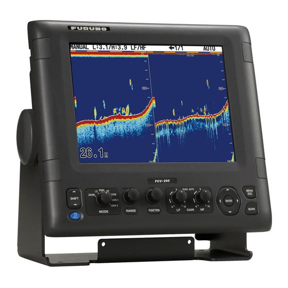
COLOR LCD SOUNDER
www.furuno.com
FCV-295
Model
Advertisement
Table of Contents

Related Manuals for Furuno FCV-295


Summary of Contents for Furuno FCV-295
-
Page 1: Table Of Contents
Installation Manual COLOR LCD SOUNDER FCV-295 Model SAFETY INSTRUCTIONS ................i SYSTEM CONFIGURATION ..............iii EQUIPMENT LISTS..................iv 1. MOUNTING .................... 1 Display Unit ........................1 Transducer ........................2 Water Temperature/Speed Sensor ................2 2. WIRING ....................3 Interconnection ......................3 Cable Fabrication ......................4 Input/Output Sentences....................6... -
Page 3: Safety Instructions
Electrolytic corrosion can, in the worst of the equipment is solely responsible for the proper installation of the equipment. case, result in loss of the transducer. FURUNO will assume no responsibility for any damage associated with improper Do not disassemble or modify the installation. - Page 4 CAUTION CAUTION Ground the equipment to The transducer cable must be prevent mutual interference. handled carefully, following the guidelines below. • Keep fuels and oils away from the cable. Observe the following compass safe • Locate the cable where it will not be distances to prevent interference to a damaged.
-
Page 5: System Configuration
SYSTEM CONFIGURATION Basic configuration is shown with solid line. Display unit CV-295 12-24 VDC Navigator Rectifier PR-62 100/110/115/ 220/230 VAC 1 , 50/60 Hz Water Temperature Sensor T-04MSB, T-04MTB Water Temp.+Speed Sensor ST-02MSB, ST-02PSB High Freq. Low Freq. Transducer Transducer... -
Page 6: Equipment Lists
EQUIPMENT LISTS Standard supply Name Type Code No. Remarks Display Unit CV-295 Spare Parts SP02-05501 001-032-740 1 set See packing list at back of this Accessories FP02-05700 000-011-976 1 set manual. Installation Materials CP02-08401 001-032-750 1 set Option Name Type Code No. - Page 7 Combination of transducer, thru-hull pipe and tank Output Frequency Ship type Transducer Thru-hull pipe Tank (kHz) 1k/1k 28/50 Steel 28F-8 TWB-6000(2) T-656 50B-9B 28/88 Steel 28F-8 TWB-6000(2) T-657 88B-8 50/88 Steel 50B-9B TWB-6000(2) T-658 88B-8 50/200 Steel 50/200-1T TFB-5000(1) T-603 50/200-1ST T-603F Steel...
- Page 8 Output Frequency Ship type Transducer Thru-hull pipe Tank (kHz) 38/88 Steel 38BL-15HR TFB-7000(2) T-682 3k/3k 88F-126H TRB-1100(2) T-682-F 38/150 Steel 38BL-15HR TFB-7000(2) T-683 150B-12H TRB-1100(2) T-683-F 38/200 Steel 38BL-15HR TFB-7000(2) T-683 200B-12H TRB-1100(2) T-683-F Steel 50BL-24HR TFB-7000(2) T-682 50/88 88F-126H TRB-1100(2) T-682-F 50/150...
- Page 9 Output Frequency Ship type Transducer Thru-hull pipe Tank (kHz) Steel 28BL-12HR TFB-4000(1) T-616 TRB-1000(1) T-616-F Steel 38BL-15HR TFB-4000(1) T-616 TRB-1000(1) T-616-F Steel 50BL-24HR TFB-4000(1) T-616 TRB-1000(1) T-616-F Steel 68F-30H TFB-5000(1) T-614 TRB-1000(1) T-614-F Steel 88F-126H TFB-4000(1) T-618 TRB-1000(1) T-618-F Steel 100B-10R TFB-5000(1) T-609...
-
Page 10: Mounting
1. MOUNTING NOTICE Do not apply paint, anti-corrosive sealant or contact spray to coating or plastic parts of the equipment. Those items contain organic solvents that can damage coating and plastic parts, especially plastic connectors. Display Unit WARNING Turn off the power at the switchboard before beginning the installation. -
Page 11: Transducer
Transducer The performance of the echo sounder depends upon the transducer position. A place least affect- ed by air bubbles should be selected since turbulence blocks the sounding path. Further, select a place least influenced by engine noise. It is known that air bubbles are fewest at the place where the bow first falls and the next wave rises, at usual cruising speed. -
Page 12: Wiring
12-24 VDC Transducer * Transducer Water temperature (Connect to a dedicated sensor breaker in the power distributor.) *: This unit cannot accept transducers of 53 to 65 kHz, 111 to 139 kHz and 171 to 183 kHz. Wiring diagram for FCV-295... -
Page 13: Cable Fabrication
Cable Fabrication Power cable This echo sounder is designed to be powered with 12-24 VDC. Use the cable DPYCY-1.5 (Japan Industry Standard) or equivalent. Approx. 70 DPYCY-1.5 Armor Armor Sheath Sheath Sheath Vinyl tape Crimp-on lug Conductor FV2-M4 13.7 mm S = 1.5 mm = 1.56 mm Clamp armor with cable clamp. - Page 14 WAGO connector (for transducer and NMEA ports) Press Opener (big one: for transducer port small one: for NMEA port) 1. Twist conductors. 2. Insert opener and press it down. 3. Insert core to hole. Twist. 4. Release opener. Core 5. Pull the core to confirm that it is tightly fastened.
-
Page 15: Input/Output Sentences
Input/Output Sentences Input sentences Sentence Data Remarks Range/bearing to waypoint Time, position GPS position GRI, Time difference Loran C Latitude and longitude GPS position GNSS position fixing Time difference Loran C Ship's heading, deviation, variation True heading Weather information Water temperature Wind direction, wind speed (true or apparent) Latitude and longitude, TD, ground speed and course Loran C... -
Page 16: Initial Setting
3. INITIAL SETTING This chapter provides the information necessary for initial setup of the equipment. First turn on the power and set display language. Then, set transducer used, by model number (FURUNO trans- ducer only) or by specifications. Language Setting 1. -
Page 17: Transducer Data
Set the transducer model number properly. Wrong transducer setting can damage the transducer and void the warranty. 3.2.1 How to enter transducer data by transducer model The following table shows the transducers programmed in the FCV-295. Type Output (kW) Type Output (kW) 28F-8... - Page 18 Note: The “XDCR Setting” dialog box (see the illustration that follows step 1 below) only appears when turning on the power after installation, after setting the desired language and the units of measurement (see section 3.1). To open the “XDCR Setting” dialog box after completion of the transducer setting, turn off the power, then turn on the power while pressing any key.
- Page 19 6. Press to select "Transducer" and then press the ENTER key. The list of programmed trans- ducers appears. 200B-5S 50/200-1T 50/200-1ST 200B-8B 200B-12H (Example: 200 kHz) 7. Press select transducer connected and then press the ENTER key. 8. Jot down the alphabet which appears on the "Tap" line. You may need to change the tap set- ting at the rear of the display unit depending on the transducer type which is connected.
- Page 20 Note: The transducers of 53 - 65 kHz, 111 to 139 kHz and 171 - 183 kHz cannot be connected to the FCV-295 because of noise. 1. At the XDCR Setting dialog box, select "XDCR Select" and press the ENTER key.
- Page 21 Tap setting for manual setting When you install the transducers whose type is not programmed, confirm the bottom echo to se- lect the optimum tap setting. The output power of the tap setting; A < B < C < D < E. CAUTION CAUTION Turn off the unit to change the tap...
- Page 22 5. When the color of the bottom echo is not stabilized in middle colors, confirm the multiple-echo at the deep see areas. Display example: Multiple-echo Set the range to integral multiple of the bottom, and then adjust the gain to stabilize the color of the multiple-echo in middle colors.
-
Page 23: Speed/Water Temperature Sensor Calibration
8. Compare the gain value and setting value on [Gain ADJ] to the one level lower tap setting. When the gain value is more than 0.2 lower or the setting value on [Gain ADJ] is more than 1.0 lower than the value of one level lower tap setting, go to step 7. Otherwise go to next step. 9. -
Page 24: Nmea Port Setting
5. To calibrate the speed value, press to select "Speed(STW)" and then press the ENTER key. 6. Press to set the value for the speed calibration and then press the ENTER key. For example, if the speed indication is 5% lower than the actual value, set +5%. 7. - Page 25 NMEA Output: Set the output data sentences. • Off: Outputs the "output data sentences" created in the FCV-295 (see page 8). • On: Outputs the "output data sentences" of FCV-295 and sentences which are input from other equipment. WAAS Setup: Choose how to use the WAAS signal when connecting with a WAAS capable GPS receiver, for example GP-320B/330B.
-
Page 26: Appendix1 Transducer 82B-35R
APPENDIX1 TRANSDUCER 82B-35R The 82B-35R is a transducer with wide bandwidth of 65 kHz-110 kHz. It is constructed to provide protection against slamming. Transducer, thru-hull pipe and tank list Frquency Transducer Hull Tank Fasten inside Fasten outside (kHz) Material (Code No.) hull (Code No.) hull (Code No.) 50/82... - Page 27 Setting for dual frequency transmitting 1. Set the XDCR SELECT menu as follows (see page 11 and 12). Setting for “HF” connection Setting for “LF” connection 2. Press the [PWR] key to turn the power off, and turn it on again. 3.
-
Page 28: Appendix2 Installation Of Temperature Sensors
APPENDIX2 INSTALLATION OF TEMPERATURE SENSORS The installation instructions in this chapter are copied from the manufacturer's (AIRMAR Technol- ogy Corporation) installation guide, which is included with your sensor. The model numbers mentioned within the documentation should be read as follows: T42 →... - Page 29 9-12 mm (3/8-1/2") pour in larger than the casting hole through the epoxy hull’s outer skin inner skin core hull thickness hull nut hull solid or hollow cylinder outer skin bedding Figure 1. Bedding and installing Figure 2. Preparing a cored fiberglass hull Copyright ©...
- Page 30 Maintenance & Replacement Aquatic growth can accumulate rapidly on the sensor’s surface reducing its performance within weeks. Clean the surface with a ® Scotch-Brite scour pad and mild household detergent taking care to avoid making scratches. If the fouling is severe, lightly wet sand with fine grade wet/dry paper.
- Page 31 OWNER’S GUIDE & INSTALLATION INSTRUCTIONS Surface Mount, Analog Record the information found on the cable tag for future reference. Part No._________________Date___________ Temperature Sensor Model T80 Follow the precautions below for optimal product performance and to reduce the risk of property damage, personal injury, and/or death. Tools &...
- Page 32 Mount the sensor near the centerline and close to the bottom of Cable Routing & Connecting the transom. 1. Route the cable to the instrument, being careful not to tear the cable jacket when passing it through the bulkhead(s) and other Route the sensor cable over the transom, through a drain hole, or parts of the boat.
- Page 40 ・FURUNO Authorized Distributor/Dealer 9-52 Ashihara-cho, Nishinomiya, 662-8580, JAPAN A : APR 2008 Printed in Japan All rights reserved. E1 : JUL . 14, 2015 Pub. No. IME-23760-E1 ( TAHA ) FCV-295 0 0 0 1 6 8 5 1 4 1 4...