Table of Contents
Advertisement
Quick Links
Advertisement
Table of Contents
Troubleshooting

Related Manuals for Furuno FCV-1100L


Summary of Contents for Furuno FCV-1100L
- Page 1 COLOR LCD SOUNDER FCV-1100L...
- Page 2 9 - 5 2 , A s h i h a r a - c h o , N i s h i n o m i y a , J a p a n T e l e p h o n e : 0 7 9 8 - 6 5 - 2 1 1 1 T e l e f a x : 0 7 9 8 - 6 5 - 4 2 0 0...
- Page 3 Continued use of the equipment can cause fire or electrical shock. Contact a FURUNO agent for service. Do not disassemble or modify the equipment. Fire, electrical shock or serious injury can result.
-
Page 4: Table Of Contents
TABLE OF CONTENTS FOREWORD... iv SYSTEM CONFIGURATION ... v OPERATIONAL OVERVIEW ... 1-1 1.1 Controls... 1-1 1.2 Indications ... 1-2 1.3 Turning the Power On/Off ... 1-2 1.4 Adjusting LCD Brilliance ... 1-3 1.5 Display Mode ... 1-4 1.6 Choosing Basic Range ... 1-11 1.7 Shifting the Basic Range... - Page 5 MAINTENANCE, TROUBLESHOOTING ... 5-1 5.1 Maintenance... 5-1 5.2 Fuse Replacement... 5-2 5.3 Troubleshooting ... 5-2 5.4 Diagnostic Test... 5-3 5.5 Test Pattern ... 5-5 5.6 Restoring Default Settings ... 5-6 APPENDIX ...A-1 Menu Tree ...A-1 Screen Division ...A-6 Display Division...A-9 SPECIFICATIONS ...SP-1 INDEX...
-
Page 6: Foreword
A Word to FCV-1100L Owners Congratulations on your choice of the FURUNO FCV-1100L COLOR LCD SOUNDER. We are confident you will see why the FURUNO name has become synonymous with quality and reliability. For over 50 years FURUNO Electric Company has enjoyed an enviable reputation for innovative and dependable marine electronics equipment. -
Page 7: System Configuration
SYSTEM CONFIGURATION System configuration... - Page 8 This page is intentionally left blank.
-
Page 9: Operational Overview
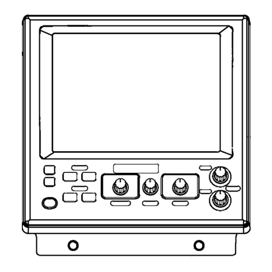
OPERATIONAL OVERVIEW Controls Correct key operation: One beep Invalid key operation: Two beeps Control Panel Adjusts display brilliance. (P. 1-3) Inscribes vertical line on the display. Current position is output to navigation plotter with connection of navigator. (P. 1-14) SHIFT/PROG MARKER BRILL Turns power... -
Page 10: Indications
1. OPERATIONAL OVERVIEW Indications Picture advance speed Water temperature* ° 5.30 Minute marker Elapsed time 0H01M (From pressing ° MARKER/TLL key) Color bar Temperature scale* Ship's speed* 17.8kt 49.6 Depth 1'21" Scroll time Turning the Power On/Off 1. Press the [PWR] key. A beep sounds, and then the power turns on. 2. -
Page 11: Adjusting Lcd Brilliance
Adjusting LCD Brilliance The brilliance of the LCD may be adjusted as below. Ten levels are available. 1. Press the [BRILL] key. 2. Press the [+] or [-] key to adjust the LCD brilliance; [+] key to raise the brilliance, [-] key to lower it. Note 1: Brilliance is automatically set to maximum at the next power on, when the unit is turned off with the brilliance setting of 4 or lower. -
Page 12: Display Mode
1. OPERATIONAL OVERVIEW Display Mode Seven display modes are available with the [MODE] switch. 1.5.1 Single-picture (low frequency or high frequency) display Low frequency (LF) The lower the frequency of the ultrasonic pulse the wider the detection area. Thus, the low frequency is suitable for general search and judging bottom condition. - Page 13 1.5.2 Dual frequency display The dual frequency display provides the low frequency picture on the left half of the screen; the high frequency picture on the right half. Frequency Beamwidth Wide High Narrow frequency Echo Trail Long Short 49.6 Dual frequency display 1.
- Page 14 1. OPERATIONAL OVERVIEW 1.5.3 Zoom displays The “single-frequency picture” (high or low frequency) appears on the right half of the screen and the zoom picture on the left half. The zoom picture may be pre-chosen among bottom lock, bottom zoom, marker zoom and discrimination, from the SYSTEM SETTING menu.
- Page 15 Bottom-zoom display The bottom-zoom display shows the zoomed bottom (automatically tracked) on the left half of the screen. When the bottom depth increases, the display shifts to keep the bottom echo at the lower part of the screen. Bottom-zoom display Marker-zoom display The marker-zoom display expands the area chosen with the VRM on the normal picture to full vertical size of the screen on the left half of the screen.
- Page 16 1. OPERATIONAL OVERVIEW DISCRIM 1/2 display The discrim(ination) 1/2 screen shows the single picture on the right half of the screen and the bottom-lock display and discriminator display occupy the left half of the screen. The discriminator display shows the bottom as a straight line, which is useful for determining bottom hardness.
- Page 17 1.5.4 USER-1, -2 displays The display programmed at USER-1/2 on the USER menu appears. The default settings are as follows: USER 1: Screen is split vertically in thirds (LF + HF + MIX) USER 2: Screen is split vertically in fourths (LF + HF + LF bottom zoom +HF bottom zoom) This setting may be changed through the USER menu.
- Page 18 1. OPERATIONAL OVERVIEW Mix display The mix display compares echo intensity between low and high frequencies, and displays echoes from tiny fish in discriminative colors. This is done by utilizing the fact that tiny fish return a stronger echo against a high frequency rather than a low frequency.
-
Page 19: Choosing Basic Range
Choosing Basic Range The basic range may be chosen with the [RANGE] switch from the eight ranges listed below. These eight ranges may be programmed as desired on the RANGE SETTING menu. For details, see page 3-5. Range setting window (example: feet) Range Unit Feet (default) Meter... -
Page 20: Shifting The Basic Range
1. OPERATIONAL OVERVIEW Shifting the Basic Range The [-] and [+] keys determine the start depth (shown at the top of the screen) of the picture. In the default setting any shift is reflected on other ranges. This feature is not available when AUTO SHIFT is active. Shift window (screen center), shift indication (top right corner) Note 1: This operation must be done within five seconds after pressing the [-] or [+] key, otherwise the shift window will be erased. -
Page 21: Adjusting Gain
Adjusting Gain The [GAIN] control adjusts the sensitivity of the receiver. Adjust it so excessive noise just disappears from the screen. Gain too high Examples of proper and improper gain levels Measuring Depth Use the [▲] or [▼] key to place the VRM on the object to measure depth. Depth is digitally displayed above the VRM. -
Page 22: Marker Line
1. OPERATIONAL OVERVIEW 1.10 Marker Line The [MARKER/TLL] key inscribes a vertical marker line on the screen when pressed. It may be used to denote a fish school or other important echo. At the same moment the key is pressed, latitude and longitude position are output to a navigation plotter and marked on its screen if this unit is interfaced with position-fixing equipment. -
Page 23: Suppressing Clutter
1.11 Suppressing Clutter When blue dots appear over the entire screen (mainly caused by sediments in the water), use the clutter function to suppress them. 1. Rotate the [FUNCTION] switch to choose CLUTTER. • For dual frequency display: Go to step 2. •... -
Page 24: Adjusting Tvg
1. OPERATIONAL OVERVIEW 1.12 Adjusting TVG The TVG compensates for propagation loss of sound, so that the echoes from the same size fish schools are displayed in the same color. Avoid excessive TVG; weak echoes may not be displayed. The TVG is also useful for reducing surface noise. -
Page 25: Eliminating Weak Echoes
5. When surface noise appears in the range shallower than the setting range, press the [▲] key to choose HF TVG LEVEL or LF TVG LEVEL as appropriate. 6. Press the [-] or [+] key to set the TVG level in the setting window. The higher the TVG level, the less the gain near distance. -
Page 26: Picture Advance Speed
1. OPERATIONAL OVERVIEW 1.14 Picture Advance Speed The picture advance speed determines how quickly the vertical scan lines run across the screen. 1. Rotate the [FUNCTION] switch to choose ADVANCE/A-SCOPE. 2. Press the [-] or [+] key to choose the speed desired. STOP Picture advance speed setting window The fractions in the window mean the number of vertical scan lines produced... - Page 27 Ship’s speed dependent mode With speed data provided by a speed log, current indicator or navigation equipment, the display advance speed may be set according to ship’s speed, the ship’s speed dependent mode. As shown in the figure below the horizontal scale of the display is not influenced by the change of ship’s speed, thus the speed-dependent picture advance permits judgment of fish school size and abundance at any speed.
-
Page 28: A-Scope Display
1. OPERATIONAL OVERVIEW 1.15 A-Scope Display The A-scope picture displays echoes at each transmission with amplitudes and colors proportional to their intensities on the right one-fourth of the screen. This feature is useful for close observation of small fish and fish near the bottom. Note: For the dual-frequency display and vertical split screen, the A-scope display is only available with the high frequency display. -
Page 29: Suppressing Interference
1.16 Suppressing Interference Interference from other acoustic equipment operating nearby or other electronic equipment on your boat may show itself on the display as shown in the figure below. You may suppress these types of interference with the noise limiter. Interference from other sounder 1. -
Page 30: Shift/Prog Key
1. OPERATIONAL OVERVIEW 3. Press the [-] or [+] key to set appropriate value in the setting window so that interference disappears. The setting range for most transducers is -10.0% to +10.0%. However the transducer listed below have different setting ranges. 50 kHz: -10% - +6% 67 kHz /68 kHz: -4% - +10% 107 kHz: -10% - +4%... -
Page 31: Menu Operation
MENU OPERATION Basic Menu Operation The main menu, consisting of the DISP (display), ALM (alarm), TX/RX, E/S and SYSTEM menus, contains various items which once preset do not require frequent adjustment. The operator may set these items as appropriate to suit operating needs. - Page 32 2. MENU OPERATION 6. Press the [-] or [+] key to change the setting. For items having several options, a scroll bar (blue) appears. This bar shows the current cursor position in relation to the entire option range. This bar shifts with operation of the [-] or [+] key.
-
Page 33: Disp Menu
Chooses eight color or sixteen-color presentation. Chooses desired picture color. USER displays the colors programmed by the user. (See page 2-16.) STD is the standard colors used on most FURUNO video sounders. HUE 1-7 provide other picture color arrangements. BACKGROUND Chooses background color to black, dark blue, blue, light-blue or white. - Page 34 2. MENU OPERATION MARKER SELECT Chooses the marker function, VRM or WHITE MARKER. VRM: Measures depth to an echo. WHITE MARKER: Display a specific echo color in white. This feature is useful for discriminating bottom fish from the bottom. (White marker operation) 1.
- Page 35 2. MENU OPERATION SCROLL TIME Turns the display scroll time on or off. Scroll time, shown at the bottom left corner of the display, shows the amount of time a scan line stays on the screen as it passes from one side of the screen to the other. Time varies with the range and picture advancement speed.
-
Page 36: Alm Menu
2. MENU OPERATION ALM Menu The ALM menu sets the bottom, fish and water temperature alarms. To silence the alarm beep, press the [-], [+], [▲] or [▼] key. BOTTOM ALARM When your ship comes in the area of the chosen depth, beeps sound and the indication “BTM”... - Page 37 4. Press the [▲] or [▼] key to choose the alarm which you want to set. 5. Press the [-] or [+] key to show the alarm setting window. FISH Bottom alarm Fish alarm 6. Press the [-] or [+] key to choose the alarm type desired. 7.
-
Page 38: Tx/Rx Menu
2. MENU OPERATION 15. Press the [-] or [+] key to set the alarm level. MIN: Alarm triggered against light-blue or stronger fish echoes. MID: Alarm triggered against yellow or stronger fish echoes. MAX: Alarm triggered against red or stronger fish echoes. 16. - Page 39 2. MENU OPERATION STC (High and Low Frequencies) Adjusts STC level for the high and low frequencies, and is useful for suppressing surface noise. The setting range is 0 (OFF) to 10. “10” suppresses noise which is up to 5 m distance from the face of the transducer. Turn off the STC when there is no noise on the screen, otherwise weak echoes may be missed.
-
Page 40: E/S Menu
2. MENU OPERATION E/S Menu The E/S menu sets echo sounder-related options. FREQ CHOICE You can change the transmitting frequencies for the following transducers. This function is useful when there is interference from other vessel, or when targeting certain fish species. 50kHz/75kHz transducer Using the following transducers with 75 kHz provides high-resolution pictures: 50B-6... - Page 41 PWR REDUCTION Reduces the power output on high and low frequencies. “<P/R>” appears at the bottom of the screen when turned on. When switching from OFF to ON, it takes several seconds to reduce power. BOTTOM SEARCH On the dual-frequency display, choose transducer which is to measure depth. The choices are AUTO, low frequency and high frequency.
-
Page 42: User Menu
2. MENU OPERATION USER Menu The USER menu sets up the user displays, user color and user clutter, and programs the [SHIFT/PROG] key. This menu can be shown by placing the [FUNCTION] switch in the “PROG” position. USER-1/2 <USER-1> NAV DATA DISP NAV DATA MODE <USER-2>... - Page 43 SCREEN LAYOUT Chooses the screen division layout among the patterns shown below. The default settings are as follows: USER-1: ( [LF]+[HF] +[MIX]) USER-2: ([LF]Zm/Nor+[HF]Zm/Nor) DISP MODE Chooses the picture to display in respective screen layout. [HF]:Normal [LF]:Normal [HF]:Zoom [LF]:Zoom [MIX]:Normal [HF]:Zm/Nor [LF]:Zm/Nor [LF]+[HF]...
- Page 44 2. MENU OPERATION NAV DATA MODE Three nav data displays are available: alphanumeric, graphic1 and graphic2. ALPHANUMERIC The alphanumeric display provides position in latitude and longitude, course, speed, depth, temperature, and range, bearing and cross-track error to the destination waypoint. Appropriate sensors are required to show data other than depth.
- Page 45 GRAPHIC2 The GRAPHIC 2 display provides a speedometer together with steering information. Appropriate sensors are required. WPT: FOX1 0.50 SHIFT/PROG KEY Chooses the function of the [SHIFT/PROG] key. The choices are shift, picture advance, signal level, hue, white line, PRR level, bottom level, A-scope, auto shift and auto mode.
- Page 46 2. MENU OPERATION USER COLOR SETTING In addition to the standard and factory-programmed color sets, the user may set and store display colors as desired. COLOR NO. GREEN BLUE DEFAULT CUSTOM Color setting for 16-color presentation. [-/+]: Change set, [EXIT]: Exit 1.
- Page 47 5. Press the [-] or [+] key to show the level setting window. Level setting window 6. Press the [-] or [+] key to select color strength. The higher the number, the darker the color. 7. Press the [▲] or [▼] key to close the level setting window. 8.
- Page 48 2. MENU OPERATION 3. Press the [-] or [+] key to set the level (1-14). If… you want to emphasize COLOR-7 (reddish-brown, red) you want to emphasize middle color (yellow, green) you want to remove the weakest color 4. Press the [▲] or [▼] key to close the setting window. 5.
-
Page 49: System Menu
SYSTEM MENU SYSTEM Menu Operation 1. Rotate the [FUNCTION] switch fully clockwise to select MENU. 2. Press the [▲] key to select the menu title area. 3. Press the [+] key to choose SYSTEM to show the SYSTEM menu. 4. Press the [▲] or [▼] key to select the item which you want to set. 5. -
Page 50: System Setting Menu
3. SYSTEM MENU SYSTEM SETTING Menu The SYSTEM SETTING menu mainly sets picture layout options. DISP PICT ADV DIR DISP DIVISION : DEPTH SCALE : RIGHT DEPTH UNIT FREE SHIFT AUTO SHIFT ZOOM MODE LANGUAGE Select picture scrolling direction. [-/+]: Change set, [EXIT]: Exit PICT ADV DIR Chooses picture advance direction: right or left which advances the picture in both right and left directions from the screen center. - Page 51 AUTO SHIFT Turns automatic depth shift on or off. The automatic shift function automatically locates the bottom trace on the lower half of the screen; the range window jumps up where the bottom trace rises over the center of the screen and jumps down when it reaches the bottom of the screen.
-
Page 52: Draft Setting Menu
3. SYSTEM MENU DRAFT SETTING Menu The DRAFT SETTING menu sets draft value, when you require depth below the surface. DRAFT Sets draft depth for low and high frequencies. DISP TX/RX SYSTEM DRAFT SETTING <High Frequency> DRAFT +0.0 ft (-15 +90) <High Frequency>... -
Page 53: Range Setting Menu
RANGE SETTING Menu The RANGE SETTING menu presets the range chosen with the [RANGE] control. DISP RANGE1 RANGE2 RANGE3 RANGE4 RANGE5 RANGE6 RANGE7 RANGE8 M/Z RANGE B/L RANGE SPLIT RANGE: OFF Set preset range scales. [-/+]: Change set, [EXIT]: Exit RANGE1-RANGE8 Presets basic ranges for the [RANGE] switch. - Page 54 3. SYSTEM MENU SPLIT RANGE Select ON to set range for low frequency and high frequency individually. 1. Rotate the [RANGE] switch to show RANGE (LF or HF) window. RANGE [LF] 30 ft 60 ft 120 ft 250 ft 500 ft 1000 ft 1600 ft 3000 ft...
-
Page 55: Temp Setting Menu
TEMP SETTING Menu The TEMP SETTING menu sets up the water temperature sensor (FURUNO- supplied sensor only). DISP TEMP UNIT TEMP INPUT TEMP ADJUST : +0.00 F (-20 TEMP OUTPUT : ON TEMP READOUT: ON TEMP GRAPH TEMP COLOR Select temperature unit. -
Page 56: 3.6 Nav Data Setting Menu
3. SYSTEM MENU TEMP COLOR Chooses the color of the temperature graph (standard, white, red, black, yellow). Note: Standard means the fifth color from the bottom of the color bar, including background color in 16-color display; third color in 8-color display. Yellow means tenth (8-color display: sixth) color from the bottom of the color bar. - Page 57 3. SYSTEM MENU NMEA VERSION Chooses NMEA version of external navigator; Ver 1.5, Ver 2.0, Ver. 3.0 or SPECIAL. If you are not sure of version number try both and select which one successfully receives data. SPECIAL outputs the depth data at the rate of 600 bps.
-
Page 58: 3.7 Target Echo Menu
3. SYSTEM MENU 3.7 TARGET ECHO Menu The TARGET ECHO menu sets fishing objective. Four choices are available: NORMAL, SURFACE, SQUID and DEEP SEA. DISP TARGET ECHO Select target echo to optimize sounding parameters. [-/+]: Change set, [EXIT]: Exit TARGET ECHO Sets up the equipment according to fishing objective NORMAL: For general fishing. -
Page 59: Interpreting The Display
INTERPRETING THE DISPLAY This section provides, using typical examples, the information necessary for interpreting the display. Minute marker Surface noise Color bar Bottom Minute Marker: The minute marker displays a minute worth of time with two colored bars, each bar 30 seconds in time. It is useful for estimating elapsed time. -
Page 60: Zero Line
4. INTERPRETING THE DISPLAY Zero Line The zero line represents the transducer’s position. It moves off the screen when a shifted range is used, or is shown at draft depth when ship’s draft is entered. Bottom Echoes Bottom echoes are normally strongest and displayed in reddish-brown or red, but colors and width will vary with bottom material, depth, sea condition, installation, frequency, pulselength and sensitivity. -
Page 61: Fish School Echoes
The nature of the bottom is known from the intensity and length of the bottom tail. Generally, when observing the bottom nature, the lower sounding frequency is used, the pulselength is set to long, and the gain setting is not disturbed. In the hard and craggy bottom, the bottom appears more reddish and with a long tail. -
Page 62: Other Echoes
4. INTERPRETING THE DISPLAY If two fish schools appear with the same color at different depths, the one in deeper water is denser because the ultrasonic wave attenuates as it propagates and the fish school in deep water tends to be displayed in a weaker color. Less Reddish (Sparse echo) Fish Echo... - Page 63 4.5.3 Surface noise When the sea is rough or the ship passes over a wake, surface noise may appear at the top of the screen. It can be suppressed with the CLUTTER function. Surface Noise 4.5.4 Aerated water When the sea is rough or the ship makes a quick turn, gaps in the bottom echo on the screen may appear.
- Page 64 4. INTERPRETING THE DISPLAY This page is intentionally left blank.
-
Page 65: Maintenance, Troubleshooting
MAINTENANCE, TROUBLESHOOTING Maintenance Regular maintenance is important for continued performance. Important points to be checked from time to time are shown below. Check point Transducer cable Power cable plug, transducer cable plug Grounding Ship’s mains voltage Display unit cleanliness Transducer cleanliness WARNING ELECTRICAL SHOCK HAZARD... -
Page 66: Fuse Replacement
5. MAINTENANCE, TROUBLESHOOTING Fuse Replacement A 5A fuse (type: FGBO-A 5A AC125V) in the power cable protects the equipment against overcurrent, reverse polarity of the ship’s mains and internal fault. If the fuse blows find the cause before replacing it. Contact your dealer about replacement. (A 7A fuse (type: FGMB 7A 125V) also is contained inside the display unit. -
Page 67: Diagnostic Test
Diagnostic Test The diagnostic test checks the equipment for proper operation. 1. Rotate the [FUNCTION] switch fully clockwise to select MENU. 2. Press the [▲] key to select the menu title area at the top of screen. 3. Press the [+] key to select SYSTEM. 4. -
Page 68: Panel Test
5. MAINTENANCE, TROUBLESHOOTING 5.4.1 Panel Test The “panel window” at the bottom of the diagnostics display is used to check keys and controls. 1. Press any key except the [PWR] key. The pressed key’s on-screen location changes from 0 to 1 when the key is pressed. 2. -
Page 69: Test Pattern
Test Pattern The test pattern tests for proper display of colors. 1. Rotate the [FUNCTION] switch fully clockwise to select MENU. 2. Press the [▲] key to select the menu title area at the top of the screen. 3. Press the [+] key to select SYSTEM. 4. -
Page 70: Restoring Default Settings
5. MAINTENANCE, TROUBLESHOOTING Restoring Default Settings All menu options can be restored to their default settings. For your reference all default settings are shown in the menu tree at the back of this manual. Note: User color setting, language, target echo setting and user clutter setting are not disturbed. -
Page 71: Appendix
APPENDIX Menu Tree [FUNCTION] switch CLUTTER SIG LEVEL ADVANCE/A-SCOPE (Continued on the next page) HF CLUTTER (0-5, 2) HF CURVE (STD, LINEAR, CUSTOM) LF CLUTTER (0-5, 2) LF CURVE (STD, LINEAR, CUSTOM) HF TVG LEV (0-10, 5) HF TVG DIST (100ft-3000ft, 600ft) LF TVG LEV (0-10, 5) LF TVG DIST (100ft-3000ft, 600ft) SIGNAL LEV (OFF, 16 colors: 1-9, 8 colors: 1-4) - Page 72 APPENDIX (Continued from previous page) PROG USER-1 SCREEN LAYOUT ( DISP MODE ZOOM MODE (BOTTOM LOCK, BOTTOM ZOOM, MARKER ZOOM, TARGET ECHO (NORMAL, SURFACE, SQUID, DEEP SEA) USER-2 SCREEN LAYOUT (Same as USER-1, default setting: DISP MODE (Same as USER-1, default setting: [LF]Zm/Nor+[HF]Zm/Nor) ZOOM MODE (Same as USER-1, default setting: BOTTOM ZOOM) TARGET ECHO (Same as USER-1, default setting: NORMAL) USER-1, USER-2...
- Page 73 (Continued from previous page) USER COLOR SETTING USER CLUTTER SETTING MENU DISP (Continued on next page) COLOR NO. (BKGD, 16 colors: ECHO1-ECHO15, 8 colors: ECHO1-ECHO7) RED (0-15, 0) GREEN (0-15, 2) BLUE (0-15, 9) DEFAULT (NO, YES) CUSTOM (NO, YES) COLOR-7 (1-14, 3) COLOR-6 (1-14, 3) COLOR-5 (1-14, 3)
- Page 74 APPENDIX (Continued from the previous page) TX/RX SYSTEM SETTING SYSTEM DRAFT SETTING RANGE SETTING (Continued on the next page) PRR LEVEL (0-20, S, 20) STC (0-10, 0) GAIN ADJ (-38-+12, +0) RX BAND (NARROW, STD, WIDE) TX PULSE (SHORT1, SHORT2, STD, LONG, MANUAL) PULSE LENGTH (0.2msec-5.0msec, 0.2msec) HF and LF should be set.
- Page 75 (Continued from previous page) TEMP SETTING NAV DATA SETTING TARGET ECHO TEST MODE DEFAULT SETTING TEMP UNIT ( C, F) TEMP INPUT (SENSOR, NMEA) TEMP ADJUST (+0.00 F, -20 - +20) TEMP OUTPUT (ON, OFF) TEMP READOUT (OFF, ON) TEMP GRAPH (OFF, NARROW, STD, EXPAND) TEMP COLOR (STD, WHITE, RED, BLACK, YELLOW) SPEED UNIT (kt, km/h, MPH) SPEED INPUT (SENSOR, NMEA)
-
Page 76: Screen Division
APPENDIX Screen Division The screen may be divided as below with SCREEN LAYOUT on the USER-1/2 sub menu of the USER menu. Full screen HIGH HIGH NORMAL ZOOM NORMAL [HF]: Normal [LF]: Normal [HF]: Zoom ZOOM NORMAL [LF]: Zoom [MIX]: Normal... - Page 77 Halves screen [HF]: Zm/Nor [LF]+[HF] NORMAL [HF]+[MIX] HIGH NORMAL HIGH ZOOM HIGH NORMAL NORMAL NORMAL HIGH APPENDIX NORMAL ZOOM [LF]: Zm/Nor HIGH ZOOM ZOOM [LF]:Zm+[HF]:Zm NORMAL NORMAL [LF]+[MIX]...
- Page 78 APPENDIX Thirds screen [LF]+[HF]: Zm/Nor [LF]+[HF]+[MIX] Fourths screen HIGH HIGH ZOOM ZOOM [LF]: Zm/Nor+[HF]: Zm/Nor HIGH NORMAL HIGH ZOOM NORMAL NORMAL HIGH NORMAL NORMAL HIGH NORMAL NORMAL ZOOM [LF]: Zm/Nor+[HF]...
-
Page 79: Display Division
Display Division The display may be divided vertically and horizontally as shown below with DISP DIVISION on the SYSTEM SETTING menu. Vertical division LF or HF NORMAL LOW/HIGH A-SCOPE LOW/HIGH "ON" DUAL HIGH LOW HIGH APPENDIX ZOOM LOW/ ZOOM HIGH... - Page 80 APPENDIX Horizontal division LF or HF NORMAL LOW/HIGH LOW/ A-SCOPE HIGH "ON" A-10 DUAL HIGH HIGH ZOOM LOW/HIGH ZOOM LOW/ HIGH ZOOM...
-
Page 81: Specifications
3.3. Output Data 4. POWER SUPPLY 4.1. Voltage and Current 4.2. Power Consumption 4.3. Rectifier (option) FCV-1100L 28/45/50/67/68/88/107/150/200 kHz, select 2 channels 1, 2 or 3 kWrms Max. 2000 pulse/min (5 to 2000 m range, normal mode) 0.2 to 5.0 msec 10.4 inch TFT color LCD, VGA: 640 x 480 pixels... - Page 82 5. ENVIRONMENTAL CONDITION 5.1. Temperature 5.2. Relative Humidity 5.3. Water Resistance 6. COATING COLOR 6.1. Display Unit -15 °C to +55 °C Less than 95% (at 40°C) Display Unit (Panel): IEC IPX5 Panel: N3.0 Sleektone No.535, Chassis: 2.5GY5/1.5 SP - 2 E2367S01C...
-
Page 83: Index
INDEX Aerated water... 4-5 ALM menu... 2-6 A-scope display ... 1-20 Automatic mode...2-11 Background color... 2-3 Bottom alarm... 2-6 Bottom echo... 4-2 Bottom level ...2-11 Bottom search...2-11 Bottom-lock display example ... 1-6 range... 3-5 Bottom-zoom display ... 1-7 BRILL key... 1-3 BTM-FISH alarm... - Page 84 INDEX Pulselength ... 2-9 PWR key ... 1-2 RANGE SETTING menu ... 3-5 RANGE switch ...1-11 RX band ... 2-9 Screen division ...2-13, A-6 Scroll time ... 2-5 Shift automatic ... 3-3 manual ... 1-12 SHIFT/PROG key operating ... 1-22 programming...