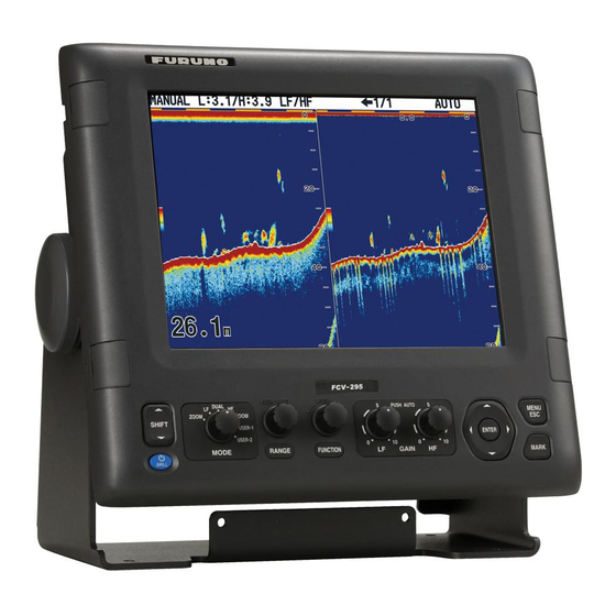
Furuno FCV-295 Operator's Manual
Color lcd sounder
Hide thumbs
Also See for FCV-295:
- Specifications (2 pages) ,
- Installation manual (32 pages) ,
- Installation manual (40 pages)
Table of Contents
Advertisement
Quick Links
Advertisement
Table of Contents
Troubleshooting

Related Manuals for Furuno FCV-295


Summary of Contents for Furuno FCV-295
- Page 1 OPERATOR'S MANUAL COLOR LCD SOUNDER FCV-295 MODEL www.furuno.co.jp...
- Page 2 Nishinomiya, 662-8580, JAPAN Telephone : +81-(0)798-65-2111 : +81-(0)798-65-4200 A : MAY 2008 Printed in Japan All rights reserved. Pub. No. OME-23760-A *00016850810* *00016850810* (AKMU ) FCV-295 *00016850810* *00016850810* * 0 0 0 1 6 8 5 0 8 1 0 *...
-
Page 3: Important Notices
• Store this manual in a convenient place for future reference. • FURUNO will assume no responsibility for the damage caused by improper use or modification of the equipment (including software) by an unauthorized agent or a third party. - Page 4 Continued use of the equipment can result if water leaks into the equipment. cause fire or electrical shock. Contact a FURUNO agent for service. Use the proper fuse. Do not disassemble or modify the Use of an incorrect fuse can damage equipment.
- Page 5 Injury can result if the glass breaks. Warning Labels Warning labels are attached to the equipment. Do not remove the labels. If a label is missing or illegible, contact a FURUNO agent or dealer about replacement. WARNING WARNING To avoid electrical shock, do not To avoid electrical shock, remove cover.
-
Page 6: Table Of Contents
TABLE OF CONTENTS FOREWORD ........v 2.4 Key Menu........29 2.5 Language Menu ......30 SYSTEM CONFIGURATION ....vi 2.6 Units Menu........30 2.7 Calib Menu........30 OPERATION ......... 1 1.1 Control Description......1 MAINTENANCE & 1.2 Power On/Off ......2 TROUBLESHOOTING....32 1.3 Adjusting Display Brilliance ..2 3.1 Maintenance ......32 1.4 Selecting a Display......2 3.2 Care of Display Unit ....32... -
Page 7: Foreword
Congratulations on your choice of the • Alarms: Bottom, Fish (bottom lock and nor- FURUNO FCV-295 Color LCD Sounder. We mal), Speed*, Water Temperature*, and Ar- are confident you will see why the FURUNO rival*. name has become synonymous with quality and reliability. -
Page 8: System Configuration
SYSTEM CONFIGURATION Basic configuration is shown below with solid line. DISPLAY UNIT CV-295 Navigation Power Equipment 12-24 VDC Rectifier PR-62 100/110/115/ 220/230 VAC 1φ, 50/60 Hz Water Temp. Sensor T-02MSB, etc. Water Temp.+Speed Sensor ST-02MSB, etc. High Freq. Freq. Transducer Transducer... -
Page 9: Operation
OPERATION Control Description HOW TO REMOVE THE HARD COVER While pressing the center of the cover with your thumbs as illustrated, pull the cover towards you. PUSH AUTO PUSH DUAL HF PUSH AUTO MENU ZOOM ZOOM SHIFT USER-1 ENTER USER-2 MODE RANGE GAIN... -
Page 10: Power On/Off
1. OPERATION Power On/Off Selecting a Display The FCV-295 has seven display modes: low Press the [ /BRILL] key to turn on the pow- frequency display, high frequency display, er. The unit beeps, the startup screen ap- dual frequency display, low frequency+zoom,... -
Page 11: Dual Frequency Display
1. OPERATION 1.4.3 Zoom display Gain - Left: Low freq. Picture advance speed Zoom mode expands chosen area of the sin- Output power lowered - Right: High freq. gle frequency picture. Five modes are avail- Interference rejector Display Range able: bottom lock, bottom zoom, marker zoom mode mode Alarm... - Page 12 1. OPERATION Bottom zoom display Bottom discrimination 1/2 display This mode expands bottom and bottom fish The bottom discrimination 1/2 screen shows on the left-half window, and is useful for deter- the single picture on the right half of the mining bottom contour.
-
Page 13: User 1 And 2 Displays
1. OPERATION Selecting a Range 1.4.4 User 1 and 2 displays The user displays let you customize displays as desired. Two displays are provided and the 1.5.1 Range adjustment default settings for each are Range can be adjusted manually or automat- User 1 display: This screen is split vertically ically. -
Page 14: Shifting The Range
1. OPERATION Shifting the Range and high frequencies alternately. For de- tails see “Split Range” in section 2.3 The basic range and range shifting functions “Range Menu”. used together give you the means to select 2. Rotate the [RANGE] control to select a the depth you can see on the screen. -
Page 15: Adjusting The Gain
1. OPERATION Adjusting the Gain 2. Use to select Fishing, Cruising or Off as appropriate. The gain may be adjusted automatically Fishing: This mode clearly displays (Fishing or Cruising) or manually. In automat- weaker echoes and is for searching fish ic operation, the gain is automatically adjust- schools. -
Page 16: Measuring Depth
6. Press the [ENTER] key (or ) to save the setting. The setting box or window disap- The FCV-295 has six menus: Sounder, TxRx, pears. To escape without changing set- Display, Alarm, Data, and System (with nine ting, press the [MENU/ESC] key instead sub menus). -
Page 17: Picture Advance Speed
1. OPERATION 1.10 Picture Advance 3. Use to select Pic. Advance and press the [ENTER] key. Speed The picture advance speed determines how Fast quickly the vertical scan lines run across the screen. When choosing a picture advance speed, keep in mind that a fast advance speed will expand echoes horizontally on the screen and a slow advance speed will con- Slow... -
Page 18: Erasing Weak Echoes
1. OPERATION 1. Press the [MENU/ESC] key to open the 2. Use to select Sounder and press menu. the [ENTER] key. 2. Use to select Sounder and press 3. Use to select Color Erase and the [ENTER] key. press the [ENTER] key. 3. -
Page 19: Adjusting Tvg
1. OPERATION 3. Use to select Clutter and press the setting, the greater the degree of clut- the [ENTER] key. ter rejection. 8. Press the [MENU/ESC] key several times to close the window. 1.14 Adjusting TVG A fish school at a deep depth is displayed in weak colors even if it is equal in strength to one in shallow waters. -
Page 20: A-Scope Display
1. OPERATION 1.15 A-scope Display 3. Use to select TVG and press the [ENTER] key. This display shows echoes at each transmis- sion with amplitudes and tone proportional to their intensities, on the right side of the screen. It is useful for estimating the type of fish school and bottom composition. -
Page 21: Alarms
(outside alarm) the preset 1.16 Alarms speed. The FCV-295 has six conditions which gener- Arrival alarm: The "Inside" arrival alarm ate both audio and visual alarms: bottom alerts you when you approach to the destina- alarm, normal fish alarm, bottom lock fish tion waypoint by the distance set. - Page 22 1. OPERATION 3. Use to select an alarm and press the transducer, and for Fish (B/L), from the [ENTER] key. the bottom. Alarm icon* Starting point Alarm range Bottom Temperature, Fish (Normal) Speed and alarm Fish (B/L) Arrival alarms alarms 4.
-
Page 23: Function Control
1. OPERATION 1.17 FUNCTION Control 1.17.2 Programming the FUNC- TION control The [FUNCTION] control provides for instant 1. Push and hold down the [FUNCTION] display of a user-defined option’s window, control until the FUNC key setting window chosen with "FUNC Key" on the Key menu. 14 appears. -
Page 24: Waypoints
This feature requires position data, fed from a GPS navigator. 1.18.1 Entering a waypoint Note 1: When TLL or FURUNO-TLL is There are two ways to enter a waypoint: di- selected at TLL Output on the NMEA rectly enter it from the screen, or manually en-... -
Page 25: Editing Waypoints
1. OPERATION Entering a waypoint by manual entry of 6. Enter latitude and longitude, similar to how entered waypoint name. position 7. Press the [MENU/ESC] key to register the 1. Press the [MENU/ESC] key to open the waypoint. menu. 8. Press the [MENU/ESC] key several times 2. -
Page 26: Setting Destination Waypoint
1. OPERATION 1.18.4 Setting destination way- Zoom Mode: Select the zoom display to show, among bottom lock, bottom zoom, point marker zoom and bottom discrimination (1/2, Set a destination waypoint to find range, bear- 1/3), when "zoom" is selected with the ing and time-to-go to that point. - Page 27 1. OPERATION Freq. Choice: You can register up to four dif- ture for the frequency selected here is ferent frequencies for a single transducer, fol- shown on the display. lowing the procedure in "Freq. Control" in the Freq Control: Four different transducer fre- Sounder menu.
- Page 28 1. OPERATION 2. Use to select a frequency and 1. Select White Line and press the [ENTER] press the [ENTER] key. key. 3. Use to select a frequency termi- nal and press the [ENTER] key. To adjust the frequency of the transducer connect- ed to the HF terminal, select HF terminal;...
- Page 29 1. OPERATION 1. Select White Marker and press the [EN- 1. Choose Bottom Zone and press the [EN- TER] key. TER] key. Boundary line (top) Bottom display area Boundary line (bottom) 2. Use to select the boundary line to adjust. 3.
-
Page 30: Tx/Rx Menu
1. OPERATION 1.19.2 Tx/Rx menu Std setting. Short 2 raises the detection reso- lution, however, detection range is shorter (pulse length is about 1/2 of Std) than the Std setting. Std is the standard pulse length, and is suitable for general use. Long Increases the detection range but resolution is two times lower compared to the Std pulse length. -
Page 31: Data Menu
1. OPERATION Depth Size: Change the size of the depth in- Background: Change the background to suit dication, to Small, Middle or Large. Off turns your current environment. The choices are off the depth indication. white, light blue, blue, dark blue, and black. This feature is inoperative when Hue is select- Depth Scale: Select where to display the ed to Custom. - Page 32 1. OPERATION Data Box1, Data Box2: Turn on to display 6. Repeat steps 4 and 5 as necessary. data at the upper left corner on the display. If 7. Use to select Switching Cycle and several data items are turned on, they are dis- then press the [ENTER] key.
-
Page 33: System Menu
SYSTEM MENU How to Open the 2.2.1 User menu description System Menu User Color Press the [MENU/ESC] key to open the Arrange the display colors to your liking by menu, then press to select System. changing the color arrangement on the color bar. - Page 34 2. SYSTEM MENU User Clutter User 1, User 2 Select the colors to reject with the clutter re- Define what to show on the two user display jector. mode screens, selectable with the [MODE] control. 1. Select User Clutter and press the [EN- TER] key to show the user clutter color Screen Layout: Select the screen layout, bar.
-
Page 35: Selecting Data For Nav Data Displays
2. SYSTEM MENU About the mix display Smoothing, Off. Deep Sea is the same as Normal. The mix display compares echo intensity be- tween low and high frequencies, and displays Nav Data Disp: Turn the nav data display On echoes from tiny fish in discriminative colors. or Off and select character size, from large or This is done by utilizing the fact that tiny fish small. - Page 36 2. SYSTEM MENU 3. Use to select the nav data item to display. Availability depends on how MARINA SPEED (SOG) PORT 0.20 much nav data is displayed, as shown be- low. 27.3 SPEED (STW) WIND True Two-data Four-data Three-data display display display Items displayable in (1) - (3): speed (STW)*,...
-
Page 37: Range Menu
2. SYSTEM MENU Range Menu B/L Range Set display range for bottom lock and bottom The Range menu is where you can pre-set discrimination displays. Use to set B/ basic ranges, zoom range, bottom lock range, L range as desired. For the horizontal split and turn independent range adjustment on or screen, the range is one-half the value set. -
Page 38: Language Menu
2. SYSTEM MENU Language Menu Calib Menu The Language menu selects the language to use. Select Language and press the [ENTER] key. Use to select language. Sound Speed Adjust the sound velocity of the Tx/Rx signal if the depth indication is incorrect, because of water temperature or salinity density. - Page 39 2. SYSTEM MENU Bottom Level Zero Line Area In the default bottom level setting (0), the This feature adjusts the rejection width of the equipment judges consecutive strong echoes transmission line from the area specified to be bottom echoes. If, in that setting, the when the menu item Zero Line is turned off.
-
Page 40: Maintenance & Troubleshooting
MAINTENANCE & TROUBLE- SHOOTING Care of Display WARNING Unit ELECTRICAL SHOCK HAZARD For the chassis, dust or dirt on the cabinet can Do not open the equipment. be removed with a soft, dry cloth. For stub- born dirt, water-diluted mild detergent can be Hazardous voltage exists inside the used. -
Page 41: Fuse Replacement
3. MAINTENANCE & TROUBLESHOOTING Fuse Replacement Symptom Remedy / Possible cause The two fuses (Type: FGMB 125V 6A PBF, Neither echo • Check battery voltage. nor fixed range • Check fuse. Code No.: 000-157-492-10) inside the display scale appears. • Check power cable. unit protect the equipment from overcurrent. - Page 42 3. MAINTENANCE & TROUBLESHOOTING 2. Press to select Tests to show the 4. Press to select Test and then Tests menu. press the [ENTER] key. The self test re- sults appear together with the key test screen, as shown above. 5.
-
Page 43: Lcd Test
3. MAINTENANCE & TROUBLESHOOTING LCD Test 3.10 Restoring Default Settings The LCD test checks for proper display of all colors. To stop the test at any time, press the You may wish to restore default settings to [MENU/ESC] key. start afresh. 1. -
Page 44: Menu Tree
APPENDIX 1 MENU TREE Bold Italic: Default Pic. Advance (4/1, 2/1, 1/1, 1/2, 1/4, 1/8, 1/16, Stop) Sounder MENU/ESC Zoom Mode (Bottom Lock, Bottom Zoom, Marker Zoom, Discrim1/2, Discrim1/3) Free Shift (Off, On) Auto Shift (Off, On) Interference (Off, Low, Medium, High, Auto) Freq Choice (Settings according to transducer connected.) Freq Control (Settings according to transducer connected.) Color Erase (0 - 50%;... - Page 45 APPENDIX 1 MENU TREE Display A-Scope (Off, Normal, Peak) Depth Size (Off, Small, Middle, Large) Depth Scale (Right, Center, Off) Zoom Marker (Off, On) Temp Graph (Off, Narrow, Wide) Temp Graph Color (Std, White, Red, Black, Yellow) Pic. Adv. Dir (Left, Right, L/R) Display Division ( Color Bar (Off, On) Hue (Custom, Std, Hue1 - Hue6)
- Page 46 NMEA0183 (Ver 1.5, Ver 2.0, Ver 3.0, Special) NMEA Port (In/Out, In/In) NMEA Output (Off, On) WAAS Setup (Off, WAAS-00 - WAAS-27) TLL Output (Off, TLL, FURUNO-TLL) Port Monitor (Set up data ports, by installer.) Sound Speed (200.0 - 2000.0 m/s; 1500.0 m/s) Calib.
-
Page 47: Screen Layout
APPENDIX 2 SCREEN LAYOUT The screen may be divided as desired with Screen Layout on the User menu. No split HIGH HIGH ZOOM NORMAL NORMAL [HF]: Normal [LF]: Normal [HF]: Zoom ZOOM NORMAL [LF]: Zoom [MIX]: Normal AP-4... - Page 48 APPENDIX 2 SCREEN LAYOUT Two-way split HIGH NORMAL NORMAL HIGH ZOOM ZOOM [HF]: Zm/Nor [LF]: Zm/Nor HIGH HIGH NORMAL ZOOM NORMAL ZOOM [LF]+[HF] [LF]:Zm+[HF]:Zm NORMAL NORMAL HIGH NORMAL NORMAL [HF]+[MIX] [LF]+[MIX] L NORMAL1 H NORMAL1 L NORMAL2 H NORMAL2 H2+H1 L2+L1 Note 1: For the vertical split (1:2), HZm+HF, LZm+LF, LF+HF, LZm+HZm, HF+Mix, LF+Mix only.
- Page 49 APPENDIX 2 SCREEN LAYOUT Three-way split HIGH HIGH NORMAL NORMAL HIGH NORMAL ZOOM ZOOM NORMAL [LF]+[HF]: Zm/Nor [LF]: Zm/Nor+[HF] NORMAL HIGH NORMAL NORMAL [LF]+[HF]+[MIX] Four-way split HIGH HIGH ZOOM ZOOM [LF]: Zm/Nor+[HF]: Zm/Nor AP-6...
-
Page 50: Screen Division
APPENDIX 3 SCREEN DIVISION The display may be divided vertically and horizontally as shown below, with Disp Division in the Display menu. Horizontal division ZOOM ZOOM LF or HF DUAL HIGH HIGH NORMAL LOW/HIGH ZOOM ZOOM HIGH HIGH LOW/ A-SCOPE HIGH "ON"... -
Page 51: Specifications
FURUNO FCV-295 SPECIFICATIONS OF COLOR LCD SOUNDER FCV-295 ECHO SOUNDER TX frequency 28/38/50/68/82/88/107/150/200 kHz, select 2 channels Output power 1, 2 or 3 kW Power reduction Off/ Min/ 1 to 10/ Auto TX rate Max. 3000 pulse/min Pulselength 0.1 to 5.0 msec (manual: 0.05 to 5.0 msec) -
Page 52: Index
INDEX FUNCTION control........15 Alarms Fuse replacement ........33 activating ...........13 arrival ............13 Gain bottom ............13 adjustment...........7 fish (bottom lock)........13 Gain adjustment ..........31 fish (normal) ..........13 GAIN control ..........7 speed ............13 water temperature ........13 Header info ..........23 Arrival alarm ..........13 A-scope display...........12 Auto shift .............18 Interference rejector ........9 Background color ........23... - Page 53 INDEX System configuration........vi System menu ..........25 Target echo .......... 22 Trip distance reset........24 Trip distance source........24 Troubleshooting ..........33 TVG.............11 Tx power .............22 Tx pulse............22 Tx rate ............22 Unit menu............30 User 1 and 2 displays........26 description ...........5 User clutter..........26 User color............25 User menu...........25 VRM ..............8 Water temperature alarm ......13...