Daikin CMSQ200A7W1B Service Manual
Hide thumbs
Also See for CMSQ200A7W1B:
- Installation manual (238 pages) ,
- Operation manual (10 pages) ,
- Service manual (502 pages)

Related Manuals for Daikin CMSQ200A7W1B


Summary of Contents for Daikin CMSQ200A7W1B
- Page 1 SiBE28 - 805 SkyAir CMSQ200A7W1B, 250A7W1B FMCQ50-125A7VEB FMDQ50-125A7V3B R-410A Heat Pump 50Hz...
-
Page 2: Table Of Contents
SiBE28-805 CMS R-410A Heat Pump 50Hz 1. Introduction .................... vi 1.1 Safety Cautions ..................vi 1.2 PREFACE ....................x Part 1 General Information ............1 1. Model Names of Indoor/Outdoor Units............2 2. External Appearance................3 2.1 Indoor Units ....................3 2.2 Outdoor Units ...................3 3. - Page 3 SiBE28-805 3.6 Stopping Operation ................45 4. Protection Control .................47 4.1 High Pressure Protection Control............47 4.2 Low Pressure Protection Control............48 4.3 Discharge Pipe Protection Control ............49 4.4 Inverter Protection Control ..............50 4.5 Injection Control (only for CMSQ200A7) ..........51 5. Other Control..................52 5.1 Demand Operation .................52 5.2 Heating Operation Prohibition ..............52 6.
- Page 4 SiBE28-805 3.8 “C4” Indoor Unit: Malfunction of Thermistor (R2T) for Heat Exchanger..................147 3.9 “C5” Indoor Unit: Malfunction of Thermistor (R3T) for Gas Pipes ..148 3.10 “C9” Indoor Unit: Malfunction of Thermistor (R1T) for Suction Air..149 3.11 “CC” Indoor Unit: Malfunction of Humidity Sensor System ....150 3.12 “CJ”...
- Page 5 SiBE28-805 3.46 “U9” Indoor Unit: Malfunction of Transmission Between Indoor and Outdoor Units in the Same System........202 3.47 “UA” Improper Combination of Indoor and Outdoor Units, Indoor Units and Remote Controller.............203 3.48 “UC” Address Duplication of Centralized Controller.......205 3.49 “UE” Malfunction of Transmission Between Centralized Controller and Indoor Unit ..........206 3.50 “UF”...
- Page 6 SiBE28-805 Index ..................... i Drawings & Flow Charts ..............v Table of Contents...
-
Page 7: Safety Cautions
Introduction SiBE28-805 1. Introduction Safety Cautions Cautions and Be sure to read the following safety cautions before conducting repair work. The caution items are classified into “ Warning” and “ Caution”. The “ Warning” Warnings items are especially important since they can lead to death or serious injury if they are not followed closely. - Page 8 SiBE28-805 Introduction Caution Do not repair the electrical components with wet hands. Working on the equipment with wet hands can cause an electrical shock. Do not clean the air conditioner by splashing water. Washing the unit with water can cause an electrical shock. Be sure to provide the grounding when repairing the equipment in a humid or wet place, to avoid electrical shocks.
- Page 9 Introduction SiBE28-805 Warning Be sure to use the specified cable to connect between the indoor and outdoor units. Make the connections securely and route the cable properly so that there is no force pulling the cable at the connection terminals. Improper connections can cause excessive heat generation or fire.
- Page 10 SiBE28-805 Introduction Caution Check to see if the parts and wires are mounted and connected properly, and if the connections at the soldered or crimped terminals are secure. Improper installation and connections can cause excessive heat generation, fire or an electrical shock. If the installation platform or frame has corroded, replace it.
- Page 11 This is the new service manual for Daikin's Year 2008 CMSQ-A series Heat Pump System. Daikin offers a wide range of models to respond to building and office air conditioning needs. We are confident that customers will be able to find the models that best suit their needs.
-
Page 12: Part 1 General Information
SiBE28-805 Part 1 General Information 1. Model Names of Indoor/Outdoor Units............2 2. External Appearance................3 2.1 Indoor Units ....................3 2.2 Outdoor Units ...................3 3. Combination ....................4 3.1 Combination Overview ................4 3.2 Combination Matrix ..................4 4. Model Selection..................5 General Information... -
Page 13: Model Names Of Indoor/Outdoor Units
Model Names of Indoor/Outdoor Units SiBE28-805 1. Model Names of Indoor/Outdoor Units Indoor Units Type Model Name Power Supply Ceiling Mounted Cassette Type FMCQ 100A 125A (Round Flow) Ceiling Mounted FMDQ 100A 125A Built-In Type Outdoor Units Series Model Name Power Supply Heat Pump CMSQ... -
Page 14: External Appearance
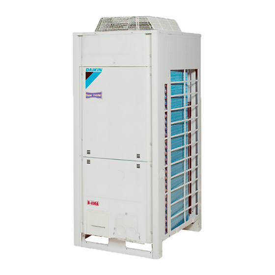
SiBE28-805 External Appearance 2. External Appearance Indoor Units Ceiling Mounted Cassette Type (Round Flow) Ceiling Mounted Built-In Type FMCQ50A FMDQ50A FMCQ60A FMDQ60A FMCQ71A FMDQ71A FMCQ100A FMDQ100A FMCQ125A FMDQ125A Outdoor Units CMSQ200A7 CMSQ250A7 General Information... -
Page 15: Combination
Combination SiBE28-805 3. Combination Combination Overview Model Name CMSQ200A7W1B CMSQ250A7W1B Notes: Explanation of connection (2~4) 2: Twin 3: Triple 4: Double twin Combination Matrix Possible indoor combination Simultaneous operation Outdoor models Twin Triple Double Twin 71-60-50(60) CMSQ200A7W1B 100-100(71) 60-60-60 50-50-50-50... -
Page 16: Model Selection
SiBE28-805 Model Selection 4. Model Selection Connectable Indoor Unit Type Model Name Power Supply Ceiling Mounted Cassette Type FMCQ 100A 125A (Multi Flow) Ceiling Mounted FMDQ 100A 125A Built-In Type Indoor unit capacity New refrigerant model code P50 type P60 type P71 type P100 type P125 type... - Page 17 Model Selection SiBE28-805 General Information...
-
Page 18: Part 2 Specifications
SiBE28-805 Part 2 Specifications 1. Specifications ..................8 1.1 Outdoor Units ...................8 1.2 Indoor Units ....................11 Specifications... -
Page 19: Specifications
Specifications SiBE28-805 1. Specifications Outdoor Units CMSQ200, 250A7W1B Heat Pump 50Hz TECHNICAL SPECIFICATIONS CMSQ200A7W1B CMSQ250A7W1B Cooling 20.0 25.0 Capacity Heating 22.4 28.0 Cooling 3.03 3.71 Heating 3.86 4.10 Capacity Range Cooling 6.60 6.74 Power Input (nominal)(50Hz) Heating 5.80 6.83 PED Category... - Page 20 SiBE28-805 Specifications TECHNICAL SPECIFICATIONS CMSQ200A7W1B CMSQ250A7W1B Sound Power (Nominal) Cooling Sound Pressure Sound level (Nominal) Level 1 / Level 2 / Night Quiet 55 / 50 / 45 Level 3 Name R-410A Charge Refrigerant Control Expansion Valve (Electronic Type) Nr of Circuits...
- Page 21 Specifications SiBE28-805 ELECTRICAL SPECIFICATIONS CMSQ200A7W1B CMSQ250A7W1B Name Phase Power Supply Frequency Voltage Cooling 9.53 9.73 Nominal Running Current (RLA) Heating 8.38 9.86 Minimum Ssc Value 1,218 Current Minimum Circuit Amps (MCA) 11.9 18.5 Maximum Fuse Amps (MFA) Total Overcurrent Amps (TOCA) 15.6...
-
Page 22: Indoor Units
SiBE28-805 Specifications Indoor Units FMCQ50-125A7VEB FOR INDOOR UNITS ONLY FMCQ50A7VEB FMCQ60A7VEB FMCQ71A7VEB FMCQ100A7VEB FMCQ125A7VEB Cooling 10.0 12.5 Nominal Input (Indoor only) Heating 11.2 14.0 TECHNICAL SPECIFICATIONS FMCQ50A7VEB FMCQ60A7VEB FMCQ71A7VEB FMCQ100A7VEB FMCQ125A7VEB Casing Material Galvanised Steel Plate Height Packing Width Depth Dimensions Height Unit... - Page 23 Specifications SiBE28-805 TECHNICAL SPECIFICATIONS FMCQ50A7VEB FMCQ60A7VEB FMCQ71A7VEB FMCQ100A7VEB FMCQ125A7VEB Item Operation Manual Quantity Item Installation Manual Quantity Drain Hose Clamp for Drain Hose Standard Accessories Washer for Hanging Bracket Screws Item Installation Guide Insulation for Fitting Sealing Pads Drain Sealing Pad The sound pressure values are mentioned for a unit installed with rear suction The sound power level is an absolute value indicating the power which a sound source generates.
- Page 24 SiBE28-805 Specifications FMDQ50-125A7V3B FOR INDOOR UNITS ONLY FMDQ50A7V3B FMDQ60A7V3B FMDQ71A7V3B FMDQ100A7V3B FMDQ125A7V3B Cooling 10.0 12.5 Nominal Input (Indoor only) Heating 11.2 14.0 Cooling 0.143 0.189 0.234 0.242 0.321 Nominal Total Input Power Heating 0.123 0.169 0.214 0.222 0.301 TECHNICAL SPECIFICATIONS FMDQ50A7V3B FMDQ60A7V3B FMDQ71A7V3B...
- Page 25 Specifications SiBE28-805 TECHNICAL SPECIFICATIONS FMDQ50A7V3B FMDQ60A7V3B FMDQ71A7V3B FMDQ100A7V3B FMDQ125A7V3B Air Filter Resin net with Mold Resistance Air Direction Control Up and Downwards Temperature Control Microprocessor Thermostat for Cooling and Heating PC Board Fuse Safety Devices Drain Pump Fuse Fan Motor Thermal Protector Nominal cooling capacities are based on : indoor temperature : 27°CDB, 19°CWB, outdoor temperature : 35°CDB, equivalent refrigerant piping : 8m, level difference : 0m.
-
Page 26: Part 3 Refrigerant Circuit
SiBE28-805 Part 3 Refrigerant Circuit 1. Refrigerant Circuit .................16 1.1 CMSQ200A7 ..................16 1.2 CMSQ250A7 ..................18 2. Functional Parts Layout ................20 2.1 CMSQ200A7 ..................20 2.2 CMSQ250A7 ..................21 3. Refrigerant Flow for Each Operation Mode...........22 Refirgerant Circuit... -
Page 27: Refrigerant Circuit
Refrigerant Circuit SiBE28-805 1. Refrigerant Circuit CMSQ200A7 No. in refrigerant Symbol Name Major Function system diagram Inverter compressor is operated on frequencies between 52Hz and 188Hz by using the inverter. The number of operating steps is as follows when Inverter compressor is Inverter compressor (INV) operated. - Page 28 SiBE28-805 Refrigerant Circuit CMSQ200A7 4TW31345-1 Refirgerant Circuit...
-
Page 29: Cmsq250A7
Refrigerant Circuit SiBE28-805 CMSQ250A7 No. in refrigerant Symbol Name Major Function system diagram Inverter compressor is operated on frequencies between 52Hz and 266Hz by using the inverter, while Standard compressor is operated with commercial power supply Inverter compressor (INV) only. The number of operating steps is as follows when Inverter compressor is operated in combination with Standard compressor. - Page 30 SiBE28-805 Refrigerant Circuit CMSQ250A7 4TW31355-1 Refirgerant Circuit...
-
Page 31: Functional Parts Layout
Functional Parts Layout SiBE28-805 2. Functional Parts Layout CMSQ200A7 Plan Accumulator ass'y Heat exchanger ACCUMULATOR THERMISTOR Front View THERMISTOR Pressure switch (High pressure protection) (S1PH) 4 way valve THERMISTOR (Y3S) Solenoid valve (Hot gas bypass) THERMISTOR (Y1S) ELECTRONIC EXPANSION VALVE THERMISTOR Solenoid valve (Accumulator oil return) (Y2S) -
Page 32: Cmsq250A7
SiBE28-805 Functional Parts Layout CMSQ250A7 Plan Heat exchanger Accumulator High pressure sensor (S1NPH) THERMISTOR Front View THERMISTOR THERMISTOR ELECTRONIC ELECTRONIC THERMISTOR THERMISTOR THERMISTOR THERMISTOR Refirgerant Circuit... -
Page 33: Refrigerant Flow For Each Operation Mode
Refrigerant Flow for Each Operation Mode SiBE28-805 3. Refrigerant Flow for Each Operation Mode CMSQ200A7 Cooling Operation Indoor unit operation Fan ON Fan ON " ON " Fan OFF " OFF " " ON " Heat exchanger Heat exchanger Heat exchanger "High temperature, high pressure gas"... - Page 34 SiBE28-805 Refrigerant Flow for Each Operation Mode Cooling Oil Return Operation Indoor unit operation Fan ON Fan OFF Fan ON " OFF " " ON " " ON " Heat exchanger Heat exchanger Heat exchanger "High temperature, high pressure gas" "High temperature, high pressure liquid"...
- Page 35 Refrigerant Flow for Each Operation Mode SiBE28-805 Heating Oil Return & Defrost Operation Indoor unit operation Fan OFF Fan OFF Fan OFF " ON " " OFF " " ON " Heat exchanger Heat exchanger Heat exchanger "High temperature, high pressure gas" "High temperature, high pressure liquid"...
- Page 36 SiBE28-805 Refrigerant Flow for Each Operation Mode Heating Operation Indoor unit operation Fan ON Fan OFF " ON " " OFF " " ON " Heat exchanger Heat exchanger Heat exchanger "High temperature, high pressure gas" "High temperature, high pressure liquid" "Low temperature, low pressure"...
- Page 37 Refrigerant Flow for Each Operation Mode SiBE28-805 CMSQ250A7 Cooling Operation Indoor unit operation Fan ON Fan ON " ON " Fan OFF " OFF " " ON " "High temperature, high pressure gas" Heat exchanger Heat exchanger Heat exchanger "High temperature, high pressure liquid" "Low temperature, low pressure"...
- Page 38 SiBE28-805 Refrigerant Flow for Each Operation Mode Cooling Oil Return Operation Indoor unit operation Fan OFF Fan ON Fan ON " OFF " " ON " " ON " "High temperature, high pressure gas" Heat exchanger Heat exchanger Heat exchanger "High temperature, high pressure liquid"...
- Page 39 Refrigerant Flow for Each Operation Mode SiBE28-805 Heating Oil Return & Defrost Operation Indoor unit operation " ON " " OFF " " ON " Fan OFF Fan OFF Fan OFF "High temperature, high pressure gas" Heat exchanger Heat exchanger Heat exchanger "High temperature, high pressure liquid"...
- Page 40 SiBE28-805 Refrigerant Flow for Each Operation Mode Heating Operation Indoor unit operation Fan ON Fan LL Fan OFF " ON " " OFF " " ON " "High temperature, high pressure gas" Heat exchanger Heat exchanger Heat exchanger "High temperature, high pressure liquid" "Low temperature, low pressure"...
- Page 41 Refrigerant Flow for Each Operation Mode SiBE28-805 Refirgerant Circuit...
-
Page 42: Part 4 Function
SiBE28-805 Part 4 Function 1. Function General...................32 1.1 Symbol ....................32 1.2 Operation Mode..................33 2. Basic Control..................34 2.1 Normal Operation ...................34 2.2 Compressor PI Control................35 2.3 Electronic Expansion Valve PI Control...........37 2.4 Step Control of Outdoor Unit Fans ............37 2.5 Outdoor Unit Fan Control in Cooling Operation ........38 3. -
Page 43: Function General
Function General SiBE28-805 1. Function General Symbol Symbol Electric symbol Description or function 20S1 Four way valve (Energize during heating) – Discharge pipe superheated degree DSHi – Discharge pipe superheat of inverter compressor DSHs – Discharge pipe superheat of standard compressor –... -
Page 44: Operation Mode
SiBE28-805 Function General Operation Mode Operation in stop mode Indoor unit stop or Indoor unit thermostat ON thermostat OFF Malfunction/Standby (Retry) Restart standby Pressure (Compressor stop) equalization prior to startup Malfunction/ Standby (Retry) Indoor unit stop or thermostat OFF Startup control Pump-down Operation mode residual... -
Page 45: Basic Control
Basic Control SiBE28-805 2. Basic Control Normal Operation 2.1.1 List of Functions in Normal Operation Function of Functional Part (Electric Part Name Symbol Symbol) Normal Cooling Normal Heating PI control, High pressure PI control, High pressure protection, Low pressure protection, Low pressure ... -
Page 46: Compressor Pi Control
SiBE28-805 Basic Control Compressor PI Control Compressor PI Control Carries out the compressor capacity PI control to maintain Te at constant during cooling operation and Tc at constant during heating operation to ensure stable unit performance. [Cooling operation] Controls compressor capacity to adjust Te to Te : Low pressure equivalent saturation achieve target value (TeS). - Page 47 Basic Control SiBE28-805 Compressor Step Control Compressor operations vary with the following steps according to information in "2.2 Compressor PI Control". 50Hz Stand-alone installation CMSQ200 CMSQ250 No. 1 No. 1 STEP STEP 52 Hz 52 Hz 56 Hz 56 Hz 62 Hz 62 Hz 68 Hz...
-
Page 48: Electronic Expansion Valve Pi Control
SiBE28-805 Basic Control Electronic Expansion Valve PI Control Main Motorized Valve EV1 Control Carries out the motorized valve (Y1E) PI control to maintain the evaporator outlet superheated degree (SH) at constant during heating operation to make maximum use of the outdoor unit heat exchanger (evaporator). -
Page 49: Outdoor Unit Fan Control In Cooling Operation
Basic Control SiBE28-805 Outdoor Unit Fan Control in Cooling Operation While in cooling operation, if the outdoor temperature is low, this mode provides high-pressure control using the outdoor unit fan to retain appropriate liquid pressure, thus ensuring refrigerant circulation rate to be supplied to indoor units. Upper limit of fan revolutions: Step 8 Pc <... -
Page 50: Special Control
SiBE28-805 Special Control 3. Special Control Startup Control This control is used to equalize the pressure in the front and back of the compressor prior to the startup of the compressor, thus reducing startup loads. Furthermore, the inverter is turned ON to charge the capacitor. In addition, to avoid stresses to the compressor due to oil return or else after the startup, the following control is made and the position of the four way valve is also determined. -
Page 51: Oil Return Operation
Special Control SiBE28-805 Oil Return Operation In order to prevent the compressor from running out of oil, the oil return operation is conducted to recover oil flown out from the compressor to the system side. 3.2.1 Oil Return Operation in Cooling Operation [Start conditions] Referring to the set conditions for the following items, start the oil return operation in cooling. - Page 52 SiBE28-805 Special Control 3.2.2 Oil Return Operation in Heating Operation Oil return preparation Outdoor Unit Actuator Oil return operation Post-oil-return operation operation 124 Hz Compressor Upper limit control 176 Hz 2-steps increase/20sec. till Pc - Pe>0.4 MPa STEP7 Outdoor unit fan STEP8 STEP8 Four way valve...
-
Page 53: Defrosting Operation
Special Control SiBE28-805 Defrosting Operation To defrost the outdoor unit heat exchanger while in Evaporator, the defrost operation is conducted to recover the heating capacity. [Start conditions] Referring to the set conditions for the following items, start the defrosting operation. •... -
Page 54: Pump-Down Residual Operation
SiBE28-805 Special Control Pump-down Residual Operation 3.4.1 Pump-down Residual Operation in Cooling Operation If the liquid refrigerant stays in the Evaporator at the startup of a compressor, this liquid refrigerant enters the compressor, thus resulting in diluted oil in the compressor and then degraded lubrication performance. Consequently, in order to recover the refrigerant in the Evaporator while the compressor stops, the pump-down residual operation is conducted. -
Page 55: Standby
Special Control SiBE28-805 Standby 3.5.1 Restart Standby Used to forcedly stop the compressor for a period of 3 minutes, in order to prevent the frequent ON/OFF of the compressor and equalize the pressure within the refrigerant system. Actuator Operation Compressor Ta>30°C: STEP4 Outdoor unit fan Ta≤30°C: OFF... -
Page 56: Stopping Operation
SiBE28-805 Special Control Stopping Operation 3.6.1 When System is in Stop Mode (Normal operation stop) This mode is used to define actuator operations when the system stops. Actuator Operation Compressor Outdoor unit fan Four way valve Holds Main motorized valve (EV1) 0 pls Subcooling motorized valve (EV2) 0 pls... - Page 57 Special Control SiBE28-805 3.6.3 Stopping Operation of Slave Units During Master Unit is in Operation with Multi-Outdoor-Unit System While the master unit is in operation, this mode is used to set the refrigerant flow rate to a required level using a slave unit in the stopped mode.
-
Page 58: Protection Control
SiBE28-805 Protection Control 4. Protection Control High Pressure Protection Control This high pressure protection control is used to prevent the activation of protection devices due to abnormal increase of high pressure and to protect compressors against the transient increase of high pressure. [In cooling operation] ★... -
Page 59: Low Pressure Protection Control
Protection Control SiBE28-805 Low Pressure Protection Control This low pressure protection control is used to protect compressors against the transient decrease of low pressure. [In cooling operation] ★ In the case of multi-outdoor-unit system, the entire system performs this control in the following sequence. -
Page 60: Discharge Pipe Protection Control
SiBE28-805 Protection Control Discharge Pipe Protection Control This discharge pipe protection control is used to protect the compressor internal temperature against a malfunction or transient increase of discharge pipe temperature. ★ Each compressor performs the discharge pipe temperature protection control individually in the following sequence. -
Page 61: Inverter Protection Control
Protection Control SiBE28-805 Inverter Protection Control Inverter current protection control and inverter fin temperature control are performed to prevent tripping due to a malfunction, or transient inverter overcurrent, and fin temperature increase. ★ In the case of multi-outdoor-unit system, each INV compressor performs these controls in the following sequence. -
Page 62: Injection Control (Only For Cmsq200A7)
SiBE28-805 Protection Control Injection Control (only for CMSQ200A7) For transitional rise in discharge pipe temperature, have the liquid refrigerant flow into the suction side to reduce the discharge pipe temperature for the compressor protection. SVT = OFF HTdi: Correction value of the discharge pipe HTdi >... -
Page 63: Other Control
Other Control SiBE28-805 5. Other Control Demand Operation In order to save the power consumption, the capacity of outdoor unit is saved with control forcibly by using “Demand 1 Setting” or “Demand 2 Setting”. To operate the unit with this mode, additional setting of “Continuous Demand Setting” or external input by external control adaptor is required. -
Page 64: Outline Of Control (Indoor Unit)
SiBE28-805 Outline of Control (Indoor Unit) 6. Outline of Control (Indoor Unit) Drain Pump Control 1. The drain pump is controlled by the ON/OFF buttons (4 button (1) - (4) given in the figure below). 6.1.1 When the Float Switch is Tripped while the Cooling Thermostat is ∗... - Page 65 Outline of Control (Indoor Unit) SiBE28-805 6.1.3 When the Float Switch is Tripped During Heating Operation: During heating operation, if the float switch is not reset even after the 5 minutes operation, 5 seconds stop, 5 minutes operation cycle ends, operation continues until the switch is reset. 6.1.4 When the Float Switch is Tripped and “AF”...
-
Page 66: Louver Control For Preventing Ceiling Dirt
SiBE28-805 Outline of Control (Indoor Unit) Louver Control for Preventing Ceiling Dirt We have added a control feature that allows you to select the range of in which air direction can be adjusted in order to prevent the ceiling surrounding the air discharge outlet of ceiling mounted cassette type units from being soiled. -
Page 67: Thermostat Sensor In Remote Controller
Outline of Control (Indoor Unit) SiBE28-805 Thermostat Sensor in Remote Controller Temperature is controlled by both the thermostat sensor in remote controller and air suction thermostat in the indoor unit. (This is however limited to when the field setting for the thermostat sensor in remote controller is set to “Use”.) Cooling If there is a significant difference in the preset temperature and the suction temperature, fine... - Page 68 SiBE28-805 Outline of Control (Indoor Unit) Heating When heating, the hot air rises to the top of the room, resulting in the temperature being lower near the floor where the occupants are. When controlling by body thermostat sensor only, the unit may therefore be turned off by the thermostat before the lower part of the room reaches the preset temperature.
-
Page 69: Thermostat Control While In Normal Operation
Outline of Control (Indoor Unit) SiBE28-805 Thermostat Control while in Normal Operation The systems are set at factory to thermostat control mode using the remote controller. While in normal thermostat differential control mode (i.e., factory set mode), the thermostat turns OFF when the system reaches a temperature of -1°C from the set temperature while in cooling operation or of +1°C from that while in heating operation. -
Page 70: Electronic Expansion Valve Control
SiBE28-805 Outline of Control (Indoor Unit) Electronic Expansion Valve Control • Electronic expansion Valve Control In cooling, to maximize the capacity of indoor unit heat exchanger (evaporator), operate the electronic expansion valve under PI control so that the evaporator outlet superheated degree (SH) will become constant. -
Page 71: Freeze Prevention
Outline of Control (Indoor Unit) SiBE28-805 Freeze Prevention Freeze When the temperature detected by liquid pipe temperature thermistor (R2T) of the indoor unit heat exchanger drops too low, the unit enters freeze prevention operation in accordance with Prevention by Off the following conditions, and is also set in accordance with the conditions given below. -
Page 72: List Of Swing Flap Operations
SiBE28-805 Outline of Control (Indoor Unit) (2) The heater control (ON/OFF) Condensing pressure 50ºC 60ºC is conducted by converting equivalent saturated the heater temperature into temperature the condensing pressure equivalent saturated temperature (Tc) according to the temperature detection through the high pressure sensor (SINPH) of the outdoor unit. [Fan residual operation] While the heater turns OFF, in order to prevent the activation of the thermal protector, the fan conducts residual operation for a given period of time after the heater turns OFF. - Page 73 Outline of Control (Indoor Unit) SiBE28-805 Function...
-
Page 74: Part 5 Test Operation
SiBE28-805 Part 5 Test Operation 1. Test Operation ..................64 1.1 Installation Process ................64 1.2 Procedure and Outline ................65 1.3 Operation when Power is Turned On .............80 2. Outdoor Unit PC Board Layout .............81 3. Field Setting ..................82 3.1 Field Setting from Remote Controller .............82 3.2 Field Setting from Outdoor Unit..............96 Test Operation... -
Page 75: Test Operation Part
Test Operation SiBE28-805 1. Test Operation Installation Process Below figure shows the installation process. Install in the order of the steps shown. 3. Selection of Location 4. Inspecting and Handling the Unit 5. Placing the Unit 7. Field Wiring 6. Refrigerant Piping 8. -
Page 76: Procedure And Outline
SiBE28-805 Test Operation Procedure and Outline Follow the following procedure to conduct the initial test operation after installation. 1.2.1 Check Work Prior to Turn Power Supply On Is the wiring performed as specified? Check the below items. Is the designated wire used? Power wiring •... - Page 77 Test Operation SiBE28-805 1.2.2 Turn Power On Be sure to turn the power on 6 hours before starting operation to protect Turn outdoor unit and indoor compressors. (to power on clankcase heater) unit power on. Check to be sure the transmission is normal. Check the LED display of the The transmission is normal if the LEDs display conditions as shown in outdoor unit PC board.
-
Page 78: Leak Test And Vacuum Drying
SiBE28-805 Test Operation 1.2.3 Leak Test and Vacuum Drying The units were checked for leaks by the manufacturer. After connecting the field piping, perform the following inspections. 1.2.3.1 Preparations Referring to figure 19, connect a nitrogen tank, a cooling tank, and a vacuum pump to the outdoor unit and perform the airtightness test and the vacuum drying. -
Page 79: Pipe Insulation
Test Operation SiBE28-805 2. Following should be executed if there is a possibility of moisture remaining inside the pipe (if piping work is carried out during the raining season or over a long period of time, rainwater may enter the pipe during work). After evacuating the system for 2 hours, pressurize the system to 0.05 MPa (vacuum break) with nitrogen gas and evacuate the system again using the vacuum pump for 1 hour to –100.7 kPa (vacuum drying). -
Page 80: Important Information Regarding The Refrigerant Used
SiBE28-805 Test Operation 1.2.5.1 Important Information Regarding the Refrigerant Used This product contains fluorinated greenhouse gases covered by the Kyoto Protocol. Do not vent gases into the atmosphere. Refrigerant type: R-410A value: 1975 GWP = global warming potential Please fill in with indelible ink, the factory refrigerant charge of the product, the additional refrigerant amount charged in the field and the total refrigerant charge... - Page 81 Test Operation SiBE28-805 1.2.5.3 Stop Valve Operation Procedure Do not open the stop valve until all piping and electrical steps of "1.2.1. Check Work Prior to Turn Power Supply On" on page 65 are completed. If the stop valve is left open without turning on the power, it may cause refrigerant to build up in the compressor, leading to insulation degradation.
- Page 82 SiBE28-805 Test Operation 1.2.5.4 How to Check How Many Units are Connected It is possible to find out how many indoor units are active and connected by operating the push- button switch on the printed circuit board (A1P) of the working outdoor unit. Make sure that all the indoor units connected to the outdoor unit are active.
-
Page 83: Additional Refrigerant Charge
Test Operation SiBE28-805 1.2.5.5 Additional Refrigerant Charge Follow the procedures below. When charging a system, charging over the permissible quantity can cause liquid hammer. Always use protective gloves and protect your eyes when charging refrigerant. When the refrigerant charging procedure is done or when pausing, close the valve of the refrigerant tank immediately. -
Page 84: Before Operation
SiBE28-805 Test Operation Charging while the outdoor unit is operating 1. Completely open the gas line stop valve. Valve A must be left fully closed. Make sure the liquid stop valve is totally shut. If it is open, the refrigerant cannot be charged. Charge the additional refrigerant in its liquid state through the service port of the liquid line stop valve. - Page 85 Test Operation SiBE28-805 Pay attention to the fan. It is dangerous to inspect the unit while the fan is running. Be sure to turn off the main switch and to remove the fuses from the control circuit located in the outdoor unit.
- Page 86 SiBE28-805 Test Operation Note: Make sure that all outside panels, except for the panel on the electric box, are closed while working. Close the lid of the electric box firmly before turning on the power. Location of the dip switches, LEDs and buttons LED H1~8P Push button switches BS1~BS5 DIP switch 1 (DS1: 1~4)
- Page 87 Test Operation SiBE28-805 Setting the mode The set mode can be changed with the BS1 MODE button according to the following procedure: For setting mode 1: Press the BS1 MODE button once, the H1P LED is off For setting mode 2: Press the BS1 MODE button for 5 seconds, the H1P LED is on If the H1P LED is blinking and the BS1 MODE button is pushed once, the setting mode will change to setting mode 1.
- Page 88 SiBE28-805 Test Operation 3.2Possible settings for function D The noise of level 3 < level 2 < level 1 ( (a) This setting = factory setting 3.3Possible settings for function E and F For function E (L.N.O.P) only: the noise of level 3 < level 2 < level 1 ( For function F (DEMAND) only: the power consumption of level 1<...
- Page 89 Test Operation SiBE28-805 In the check operation, the following checks and judgement will be performed: Check of the stop valve opening Check for wrong wiring Check of refrigerant overcharge Judgement of piping length It takes ±40 minutes to complete the check operation. Perform the test operation as described in the paragraph "Test operation procedure"...
-
Page 90: Service Mode Operation
SiBE28-805 Test Operation Correcting after abnormal completion of the test operation The test operation is only completed if there is no malfunction code displayed on the remote controller. In case of a displayed malfunction code, perform the following actions to correct the abnormality: Confirm the malfunction code on the remote controller Installation error... -
Page 91: Operation When Power Is Turned On
Test Operation SiBE28-805 Operation when Power is Turned On 1.3.1 When Turning On Power First Time The unit cannot be run for up to 12 minutes to automatically set the master power and address (indoor-outdoor address, etc.). Status Outdoor unit Test lamp H2P .. -
Page 92: Outdoor Unit Pc Board Layout
SiBE28-805 Outdoor Unit PC Board Layout 2. Outdoor Unit PC Board Layout Outdoor unit PC board (2) Set mode display (LED) (3) Mode setting switch H1P H2P H3P H4P H5P H6P H7P H8P 1 2 3 4 1 2 3 4 MODE RETURN TEST... -
Page 93: Field Setting
Field Setting SiBE28-805 3. Field Setting Field Setting from Remote Controller Individual function of indoor unit can be changed from the remote controller. At the time of installation or after service inspection / repair, make the local setting in accordance with the following description. - Page 94 SiBE28-805 Field Setting 3.1.2 Wireless Remote Controller - Indoor Unit BRC7F type BRC4C type 1. When in the normal mode, push the “ ” button for 4 seconds or more, and operation then enters the “field set mode.” 2. Select the desired “mode No.” with the “ ”...
- Page 95 Field Setting SiBE28-805 3.1.3 Simplified Remote Controller BRC2A51 BRC2C51 1. Remove the upper part of remote controller. 2. When in the normal mode, press the [BS6] BUTTON ( ) (field set), and the FIELD SET MODE is entered. ▲ 3. Select the desired MODE No. with the [BS2] BUTTON ( ) (temperature setting ) and the ▼...
- Page 96 SiBE28-805 Field Setting 3.1.4 Setting Contents and Code No. – Indoor unit Mode Second Code No.(Note 3) Setting Details Setting Contents Switch Note 2 Super Filter contamination heavy/ Approx. Approx. long life light (Setting for display 10,000 hrs. 5,000 hrs. filter time to clean air filter) —...
- Page 97 Field Setting SiBE28-805 3.1.5 Applicable Range of Field Setting Ceiling mounted cassette type Ceiling mounted built-in type Details No. Round flow FMCQ FMDQ Filter sign Ultra long life filter sign — Remote controller thermostat sensor Set fan speed when (8) (11) thermostat OFF Airflow adjustment Ceiling —...
-
Page 98: Detailed Explanation Of Setting Modes
SiBE28-805 Field Setting 3.1.6 Detailed Explanation of Setting Modes (1) Filter Sign Setting If switching the filter sign ON time, set as given in the table below. Set Time Filter Specs. Standard Long Life Ultra Long Life Filter Setting Contamination Light 200 hrs. - Page 99 Field Setting SiBE28-805 (6) External ON/OFF Input This input is used for "ON / OFF operation" and "Protection device input" from the outside. The input is performed from the T1-T1 terminal of the operation terminal block (X1A) in the electric component box.
- Page 100 SiBE28-805 Field Setting (10) Auto Restart after Power Failure Reset For the air conditioners with no setting for the function (same as factory setting), the units will be left in the stop condition when the power supply is reset automatically after power failure reset or the main power supply is turned on again after once turned off.
- Page 101 Field Setting SiBE28-805 In the Case of FMCQ100~125 (* 4-Way, 3-Way, 2-Way Outlets) First Second Ceiling height Mode code code Setting 4-way Outlets 3-way Outlets 2-way Outlets Standard (N) Lower than 3.4 m Lower than 3.6 m Lower than 4.2 m 13 (23) High Ceiling (H) Lower than 3.9 m Lower than 4.0 m Lower than 4.2 m...
- Page 102 SiBE28-805 Field Setting (17) Setting of Direct Duct Connection This is used when "fresh air intake kit equipped with fan" is connected. The indoor fan carries out residual operation for one minute after the thermostat is stopped. (For the purpose of preventing dust on the air filter from falling off.) Mode No.
- Page 103 Field Setting SiBE28-805 3.1.7 Centralized Control Group No. Setting BRC1C Type In order to conduct the central remote control using the central remote controller and the unified ON/OFF controller, Group No. settings should be made by group using the operating remote controller.
- Page 104 SiBE28-805 Field Setting BRC7F Type Group No. setting by wireless remote controller for centralized control 1. When in the normal mode, push “ ” button for 4 seconds or more, and operation then BRC4C Type enters the “field set mode.” 2.
- Page 105 Field Setting SiBE28-805 3.1.8 Setting of Operation Control Mode from Remote Controller (Local Setting) The operation control mode is compatible with a variety of controls and operations by limiting the functions of the operation remote controller. Furthermore, operations such as remote controller ON/OFF can be limited in accordance with the combination conditions.
- Page 106 SiBE28-805 Field Setting How to Select Whether operation by remote controller will be possible or not for turning on/off, controlling temperature or setting operation mode is selected and decided by the operation mode given on Operation Mode the right edge of the table below. Example ON by remote OFF by remote...
-
Page 107: Field Setting From Outdoor Unit
Field Setting SiBE28-805 Field Setting from Outdoor Unit 3.2.1 Field Setting from Outdoor Unit List of Field Setting Items This following section indicates the list of field setting items. For the lists of dip switch contents, Setting mode 1, and Setting mode 2, refer to information in tables shown on the following page onward. - Page 108 SiBE28-805 Field Setting Setting item Content and objective of setting Overview of setting procedure Indoor unit fan Used to operate the indoor unit in the Set No. 5 of "Setting mode 2" to indoor unit forced H operation stopped state in forced H operation mode. forced fan H.
- Page 109 Field Setting SiBE28-805 Setting by dip switches Using dip switches on the PC board enables field setting shown below. However, make no changes of factory settings except for DS1-1. Dip switch Setting item Description Setting Used to set cool / heat select by Cool/Heat selector DS1-1 Cool / Heat select equipped with outdoor unit.
- Page 110 SiBE28-805 Field Setting “Detail of DS1-1~4, DS2-1~4 setting” (for Overseas general) Unit Setting method ( represents the position of switches) Heat Pump Set DS2-1 to ON. CMSQ200A7 Heat Pump Set DS2-1 and DS2-3 to ON. CMSQ250A7 Test Operation...
- Page 111 Field Setting SiBE28-805 Setting by push button switches The following settings are made by pushbutton switches on PC board. LED display COOL/HEAT select TEST MODE Demand Multi; noise MASTER SLAVE Single-outdoor-unit system (Factory setting) MODE RETURN TEST RESET There are the following three setting modes. Setting mode 1 (H1P off) Initial status (when normal): Used to select the cool/heat setting.
- Page 112 SiBE28-805 Field Setting a. “Setting mode 1” This mode is used to set and check the following items. 1. Set items ············ In order to make COOL/HEAT selection in a batch of outdoor unit group, change the setting. • COOL/HEAT selection (IND) ·····················Used to select COOL or HEAT by individual outdoor unit (factory set).
- Page 113 Field Setting SiBE28-805 Setting item Description b. “Setting mode 2” Used to make setting of contents to display on the digital Digital pressure pressure gauges (e.g. pressure sensors and temperature gauge kit display sensors) Push and hold the MODE (BS1) button for 5 seconds and set to Cool/heat unified Sets address for cool/heat unified operation.
- Page 114 SiBE28-805 Field Setting Setting item Description Setting of difference Make the setting when the outdoor unit is installed 40 m in elevation for the or more below the indoor unit. outdoor unit Test Operation...
- Page 115 Field Setting SiBE28-805 Setting item display C/H selection Setting condition display MODE TEST Demand Setting item noise Master Slave ∗ Factory set ∗ k h h h h h h Address k h h h h h k Binary number Digital pressure gauge kit display (4 digits)
- Page 116 SiBE28-805 Field Setting Setting item display C/H selection Setting condition display MODE TEST Demand Setting item noise Master Slave ∗ Factory set ∗ k h h h h h h k h h h h h k Level 1 (outdoor fan with 6 step or lower) 22 Night-time low noise setting k h h h h k h...
- Page 117 Field Setting SiBE28-805 c. Monitor mode LED display Setting item Data display H2P H3P H5P H6P l h h h h h h To enter the monitor mode, push the Various settings Lower 4 digits MODE (BS1) button when in l h h h h h k “Setting mode 1”.
- Page 118 SiBE28-805 Field Setting Setting item 0 Display contents of “Number of units for various settings” l h h k h h h EMG operation / backup operation l h h h h h h setting l h h h k h h Defrost select setting Short l h h h l h h...
- Page 119 Field Setting SiBE28-805 3.2.2 Cool / Heat Mode Switching There are the following 4 cool/heat switching modes. Set cool/heat separately for each outdoor unit system by indoor unit remote controller. Set cool/heat separately for each outdoor unit system by cool/heat selector. Set cool/heat for more than one outdoor unit system simultaneously in accordance with unified master outdoor unit by indoor unit remote controller.
- Page 120 SiBE28-805 Field Setting Set Cool / Heat Separately for Each Outdoor Unit System by Cool / Heat Selector It does not matter whether or not there is outdoor - outdoor unit wiring. Set outdoor unit PC board DS1-1 to OUT (factory set). Set cool/heat switching to IND (individual) for “Setting mode 1”...
- Page 121 Field Setting SiBE28-805 3.2.3 Setting of Low Noise Operation and Demand Operation Setting of Low Noise Operation By connecting the external contact input to the low noise input of the outdoor unit external control adaptor (optional), you can lower operating noise by 2-3 dB. Setting Content Mode 1...
- Page 122 SiBE28-805 Field Setting Image of operation in the case of A Image of operation in the case of B Image of operation in the case of A and B Test Operation...
- Page 123 Field Setting SiBE28-805 Setting of Demand Operation By connecting the external contact input to the demand input of the outdoor unit external control adaptor (optional), the power consumption of unit operation can be saved suppressing the compressor operating condition. Set item Condition Content Demand 1...
- Page 124 SiBE28-805 Field Setting Image of operation in the case of A Power consumption The power Rated power consumption consumption during 80 % of rated power consumption Demand level 1 instructing Demand level 2 instructing Demand level 3 instructing the demand level 1 70 % of rated power consumption instructing can be 60 % of rated power consumption...
- Page 125 Field Setting SiBE28-805 Detailed Setting Procedure of Low Noise Operation and Demand Control 1. Setting mode 1 (H1P off) → In setting mode 2, push the BS1 (MODE button) one time. Setting mode 1 is entered and H1P lights off. During the setting mode 1 is displayed, “In low noise operation”...
- Page 126 SiBE28-805 Field Setting : ON : OFF : Blink Setting Setting Setting No. indication Setting No. indication Setting Setting contents indication (Initial setting) contents contents H1P H2P H3P H4P H5P H6P H7P H1P H2P H3P H4P H5P H6P H7P H1P H2P H3P H4P H5P H6P H7P External low noise / (Factory...
- Page 127 Field Setting SiBE28-805 3.2.4 Setting of Refrigerant Recovery Mode When carrying out the refrigerant collection on site, fully open the respective expansion valve of indoor and outdoor units. All indoor and outdoor unit’s operation are prohibited. [Operation procedure] In setting mode 2 with units in stop mode, set “Refrigerant Recovery / Vacuuming mode” to ON.
- Page 128 SiBE28-805 Field Setting 3.2.5 Setting of Vacuuming Mode In order to perform vacuuming operation at site, fully open the expansion valves of indoor and outdoor units and turn on some solenoid valves. [Operating procedure] With Setting Mode 2 while the unit stops, set “Refrigerant recovery / Vacuuming mode” to ON.
- Page 129 Field Setting SiBE28-805 Test Operation...
-
Page 130: Part 6 Troubleshooting
SiBE28-805 Part 6 Troubleshooting 1. Symptom-based Troubleshooting ............121 2. Troubleshooting by Remote Controller ..........124 2.1 The INSPECTION / TEST Button............124 2.2 Self-diagnosis by Wired Remote Controller .........125 2.3 Self-diagnosis by Wireless Remote Controller ........126 2.4 Remote Controller Service Mode ............129 2.5 Remote Controller Self-Diagnosis Function .........131 3. - Page 131 SiBE28-805 3.30 “L4” Outdoor Unit: Malfunction of Inverter Radiating Fin Temperature Rise ..........175 3.31 “L5” Outdoor Unit: Inverter Compressor Abnormal .......177 3.32 “L8” Outdoor Unit: Inverter Current Abnormal........179 3.33 “L9” Outdoor Unit: Inverter Start Up Error..........181 3.34 “LC” Outdoor Unit: Malfunction of Transmission Between Inverter and Control PC Board .............183 3.35 “P1”...
-
Page 132: Symptom-Based Troubleshooting
SiBE28-805 Symptom-based Troubleshooting 1. Symptom-based Troubleshooting Symptom Supposed Cause Countermeasure The system does not start operation at all. Blowout of fuse(s) Turn Off the power supply and then replace the fuse(s). Cutout of breaker(s) • If the knob of any breaker is in its OFF position, turn ON the power supply. - Page 133 Symptom-based Troubleshooting SiBE28-805 Symptom Supposed Cause Countermeasure The system This symptom occurs The system is in preparation Wait for a period of approximately conducts fan immediately after turning ON mode of operation. 10 minutes. operation but not the power supply. cooling or heating operation.
- Page 134 SiBE28-805 Symptom-based Troubleshooting Symptom Supposed Cause Countermeasure 12 Dust comes out Dust comes out from the Dust, which has deposited on the Normal operation. from the system. system when it restarts after inside of indoor unit, is blown out the stop for an extended period from the system.
-
Page 135: Troubleshooting By Remote Controller
Troubleshooting by Remote Controller SiBE28-805 2. Troubleshooting by Remote Controller The INSPECTION / TEST Button The following modes can be selected by using the [Inspection/Test Operation] button on the remote control. Depress Inspection/Test Operation button for more than 4 seconds. Indoor unit settings can be made Service data can be obtained. -
Page 136: Self-Diagnosis By Wired Remote Controller
SiBE28-805 Troubleshooting by Remote Controller Self-diagnosis by Wired Remote Controller Explanation If operation stops due to malfunction, the remote controller’s operation LED blinks, and malfunction code is displayed. (Even if stop operation is carried out, malfunction contents are displayed when the inspection mode is entered.) The malfunction code enables you to tell what kind of malfunction caused operation to stop. -
Page 137: Self-Diagnosis By Wireless Remote Controller
Troubleshooting by Remote Controller SiBE28-805 Self-diagnosis by Wireless Remote Controller In the Case of If equipment stops due to a malfunction, the operation indicating LED on the light reception section flashes. BRC7F Type The malfunction code can be determined by following the procedure described below. (The BRC4C Type malfunction code is displayed when an operation error has occurred. - Page 138 SiBE28-805 Troubleshooting by Remote Controller The lower digit of the code changes as shown below when the UP and DOWN buttons are pressed. Troubleshooting...
- Page 139 Troubleshooting by Remote Controller SiBE28-805 Troubleshooting...
-
Page 140: Remote Controller Service Mode
SiBE28-805 Troubleshooting by Remote Controller Remote Controller Service Mode How to Enter the Service Mode Service Mode 1. Select the mode No. Set the desired mode No. with the button. Operation (For wireless remote controller, Mode 43 only can be set.) Method 2. - Page 141 Troubleshooting by Remote Controller SiBE28-805 Mode Function Contents and operation method Remote controller display example Malfunction Display malfunction hysteresis. hysteresis display The history No. can be changed with the Unit 1 button. Malfunction code 2-U4 Malfunction code Hystory No: 1 - 9 1: Latest Display of sensor Display various types of data.
-
Page 142: Remote Controller Self-Diagnosis Function
SiBE28-805 Troubleshooting by Remote Controller Remote Controller Self-Diagnosis Function The remote controller switches are equipped with a self diagnosis function so that more appropriate maintenance can be carried out. If a malfunction occurs during operation, the operation lamp, malfunction code and display of malfunctioning unit No. let you know the contents and location of the malfunction. - Page 143 Troubleshooting by Remote Controller SiBE28-805 k : ON h : OFF l : Blink Malfunction Operation Malfunction contents Page code lamp Referred Indoor Unit Error of external protection device PC board defect Malfunction of drain level control system (S1L) Fan motor (M1F) lock, overload Malfunction of moving part of electronic expansion valve (Y1E) Drain level above limit Malfunction of air filter maintenance...
- Page 144 SiBE28-805 Troubleshooting by Remote Controller k : ON h : OFF l : Blink Malfunction Operation Malfunction contents Page code lamp Referred System Low pressure drop due to refrigerant shortage or electronic expansion valve failure Reverse phase, open phase Power supply insufficient or instantaneous failure Check operation not executed Malfunction of transmission between indoor units Malfunction of transmission between remote controller and indoor unit...
- Page 145 Troubleshooting by Remote Controller SiBE28-805 Malfunction code indication by outdoor unit PC board <Monitor mode> Contents of malfunction Malfunction To enter the monitor mode, push the code MODE (BS1) button when in PC board malfunction PC board malfunction “Setting mode 1”. Faulty PC board Abnormal discharge pressure HPS activated...
- Page 146 SiBE28-805 Troubleshooting by Remote Controller k : ON h : OFF l :Blink Confirmation of malfunction 1 Confirmation of malfunction 2 Confirmation of malfunction 3 Confirmation of malfunction 4 Malfunction code H1P H2P H3P H4P H5P H6P H7P H1P H2P H3P H4P H5P H6P H7P H1P H2P H3P H4P H5P H6P H7P H1P H2P H3P H4P H5P H6P H7P ∗...
- Page 147 Troubleshooting by Remote Controller SiBE28-805 <Monitor mode> Contents of malfunction Malfunction To enter the monitor mode, push the code MODE (BS1) button when in Open phase/Power supply imbalance Imbalance of inverter power supply “Setting mode 1”. voltage Faulty temperature sensor inside Faulty thermistor of inverter box switch box Faulty temperature sensor of inverter...
- Page 148 SiBE28-805 Troubleshooting by Remote Controller k : ON h : OFF l :Blink Confirmation of malfunction 1 Confirmation of malfunction 2 Confirmation of malfunction 3 Confirmation of malfunction 4 Mal f unction code H1P H2P H3P H4P H5P H6P H7P H1P H2P H3P H4P H5P H6P H7P H1P H2P H3P H4P H5P H6P H7P H1P H2P H3P H4P H5P H6P H7P ∗...
-
Page 149: Troubleshooting By Indication On The Remote Controller
Troubleshooting by Indication on the Remote Controller SiBE28-805 3. Troubleshooting by Indication on the Remote Controller “ ” Indoor Unit: Error of External Protection Device Remote Controller Display Applicable All indoor unit models Models Method of Detect open or short circuit between external input terminals in indoor unit. Malfunction Detection Malfunction... -
Page 150: A1" Indoor Unit: Pc Board Defect
SiBE28-805 Troubleshooting by Indication on the Remote Controller “ ” Indoor Unit: PC Board Defect Remote Controller Display Applicable All indoor unit models Models Method of Check data from E²PROM. Malfunction Detection Malfunction When data could not be correctly received from the E²PROM E²PROM : Type of nonvolatile memory. -
Page 151: A3" Indoor Unit: Malfunction Of Drain Level Control System (S1L)
Troubleshooting by Indication on the Remote Controller SiBE28-805 “ ” Indoor Unit: Malfunction of Drain Level Control System (S1L) Remote Controller Display Applicable FMCQ, FMDQ Models Method of By float switch OFF detection Malfunction Detection Malfunction When rise of water level is not a condition and the float switch goes OFF. Decision Conditions Supposed... - Page 152 SiBE28-805 Troubleshooting by Indication on the Remote Controller Troubleshooting Be sure to turn off power switch before connect or disconnect connector, Caution or parts damage may be occurred. Is power supply Provide 220~240V power 220~240V provided? supply. A short The float circuit connector is switch is connected to Connect either a short circuit...
-
Page 153: A6" Indoor Unit: Fan Motor (M1F) Lock, Overload
Troubleshooting by Indication on the Remote Controller SiBE28-805 “ ” Indoor Unit: Fan Motor (M1F) Lock, Overload Remote Controller Display Applicable All indoor units Models Method of Detection by failure of signal for detecting number of turns to come from the fan motor Malfunction Detection Malfunction... -
Page 154: A9" Indoor Unit: Malfunction Of Moving Part Of
SiBE28-805 Troubleshooting by Indication on the Remote Controller “ ” Indoor Unit: Malfunction of Moving Part of Electronic Expansion Valve (Y1E) Remote Controller Display Applicable All indoor unit models Models Method of Use a microcomputer to check the electronic expansion valve for coil conditions. Malfunction Detection Malfunction... - Page 155 Troubleshooting by Indication on the Remote Controller SiBE28-805 ∗ 1: Coil check method for the moving part of the electronic expansion valve Disconnect the electronic expansion valve from the PC board and check the continuity between the connector pins. (Normal) Pin No.
-
Page 156: Af" Indoor Unit: Drain Level Above Limit
SiBE28-805 Troubleshooting by Indication on the Remote Controller “ ” Indoor Unit: Drain Level above Limit Remote Controller Display Applicable FMCQ, FMDQ Models Method of Water leakage is detected based on float switch ON/OFF operation while the compressor is in non-operation. -
Page 157: Aj" Indoor Unit: Malfunction Of Capacity Determination Device
Troubleshooting by Indication on the Remote Controller SiBE28-805 “ ” Indoor Unit: Malfunction of Capacity Determination Device Remote Controller Display Applicable All indoor unit models Models Method of Capacity is determined according to resistance of the capacity setting adaptor and the memory inside the IC memory on the indoor unit PC board, and whether the value is normal or abnormal Malfunction is determined. -
Page 158: C4" Indoor Unit: Malfunction Of Thermistor (R2T) For Heat Exchanger
SiBE28-805 Troubleshooting by Indication on the Remote Controller “ ” Indoor Unit: Malfunction of Thermistor (R2T) for Heat Exchanger Remote Controller Display Applicable All indoor unit models Models Method of Malfunction detection is carried out by temperature detected by heat exchanger thermistor. Malfunction Detection Malfunction... -
Page 159: C5" Indoor Unit: Malfunction Of Thermistor (R3T) For Gas Pipes
Troubleshooting by Indication on the Remote Controller SiBE28-805 “ ” Indoor Unit: Malfunction of Thermistor (R3T) for Gas Pipes Remote Controller Display Applicable All indoor unit models Models Method of Malfunction detection is carried out by temperature detected by gas pipe thermistor. Malfunction Detection Malfunction... -
Page 160: C9" Indoor Unit: Malfunction Of Thermistor (R1T) For Suction Air
SiBE28-805 Troubleshooting by Indication on the Remote Controller 3.10 “ ” Indoor Unit: Malfunction of Thermistor (R1T) for Suction Air Remote Controller Display Applicable AII indoor unit models Models Method of Malfunction detection is carried out by temperature detected by suction air temperature thermistor. -
Page 161: Cc" Indoor Unit: Malfunction Of Humidity Sensor System
Troubleshooting by Indication on the Remote Controller SiBE28-805 3.11 “ ” Indoor Unit: Malfunction of Humidity Sensor System Remote Controller Display Applicable FMCQ Models Method of Even if a malfunction occurs, operation still continues. Malfunction is detected according to the moisture (output voltage) detected by the moisture Malfunction sensor. -
Page 162: Cj" Indoor Unit: Malfunction Of Thermostat Sensor In Remote Controller
SiBE28-805 Troubleshooting by Indication on the Remote Controller 3.12 “ ” Indoor Unit: Malfunction of Thermostat Sensor in Remote Controller Remote Controller Display Applicable AII indoor unit models Models Method of Malfunction detection is carried out by temperature detected by remote controller air temperature thermistor. -
Page 163: E1" Outdoor Unit: Pc Board Defect
Troubleshooting by Indication on the Remote Controller SiBE28-805 3.13 “ ” Outdoor Unit: PC Board Defect Remote Controller Display Applicable CMSQ200A7, 250A7 Models Method of Check data from E²PROM Malfunction Detection Malfunction When data could not be correctly received from the E²PROM E²PROM : Type of nonvolatile memory. -
Page 164: E3" Outdoor Unit: Actuation Of High Pressure Switch
SiBE28-805 Troubleshooting by Indication on the Remote Controller 3.14 “ ” Outdoor Unit: Actuation of High Pressure Switch Remote Controller Display Applicable CMSQ200A7, 250A7 Models Method of Abnormality is detected when the contact of the high pressure protection switch opens. Malfunction Detection Malfunction... - Page 165 Troubleshooting by Indication on the Remote Controller SiBE28-805 Troubleshooting Be sure to turn off power switch before connect or disconnect connector, Caution or parts damage may be occurred. Check for the points shown below. Is the stop valve open? Is the HPS connector properly connected to the main PC board? Does the high pressure switch have continuity? Are the...
-
Page 166: E4" Outdoor Unit: Actuation Of Low Pressure Sensor
SiBE28-805 Troubleshooting by Indication on the Remote Controller 3.15 “ ” Outdoor Unit: Actuation of Low Pressure Sensor Remote Controller Display Applicable CMSQ200A7, 250A7 Models Method of Abnormality is detected by the pressure value with the low pressure sensor. Malfunction Detection Malfunction Error is generated when the low pressure is dropped under specific pressure. - Page 167 Troubleshooting by Indication on the Remote Controller SiBE28-805 Troubleshooting Be sure to turn off power switch before connect or disconnect connector, Caution or parts damage may be occurred. Is the stop Open the stop valve. valve open? Mount a pressure gauge on the low-pressure service port. Connect the Service Checker.
-
Page 168: E5" Outdoor Unit: Inverter Compressor Motor Lock
SiBE28-805 Troubleshooting by Indication on the Remote Controller 3.16 “ ” Outdoor Unit: Inverter Compressor Motor Lock Remote Controller Display Applicable CMSQ200A7, 250A7 Models Method of Inverter PC board takes the position signal from UVW line connected between the inverter and compressor, and the malfunction is detected when any abnormality is observed in the phase- Malfunction current waveform. - Page 169 Troubleshooting by Indication on the Remote Controller SiBE28-805 Troubleshooting Be sure to turn off power switch before connect or disconnect connector, Caution or parts damage may be occurred. Is the stop valve open? On-site causes. Open the stop valve. Power OFF Check the compressor cable for disconnection and flaws.
-
Page 170: E7" Outdoor Unit: Malfunction Of Outdoor Unit Fan Motor
SiBE28-805 Troubleshooting by Indication on the Remote Controller 3.17 “ ” Outdoor Unit: Malfunction of Outdoor Unit Fan Motor Remote Controller Display Applicable CMSQ200A7, 250A7 Models Method of Malfunction of fan motor system is detected according to the fan speed detected by hall IC when the fan motor runs. - Page 171 Troubleshooting by Indication on the Remote Controller SiBE28-805 Troubleshooting Be sure to turn off power switch before connect or disconnect connector, Caution or parts damage may be occurred. Turn OFF the power supply, and then wait for a period of 10 minutes.
- Page 172 SiBE28-805 Troubleshooting by Indication on the Remote Controller Troubleshooting CHECK 1 Check for the fan motor connector (Power supply cable) Resistance of the U, V, and W phases of the fan motor has got imbalanced or short Replace the outdoor unit fan circuits have been established motor.
-
Page 173: E9" Outdoor Unit: Malfunction Of Moving Part Of
Troubleshooting by Indication on the Remote Controller SiBE28-805 3.18 “ ” Outdoor Unit: Malfunction of Moving Part of Electronic Expansion Valve (Y1E, Y2E) Remote Controller Display Applicable CMSQ200A7, 250A7 Models Method of Check disconnection of connector Check continuity of expansion valve coil Malfunction Detection Malfunction... - Page 174 SiBE28-805 Troubleshooting by Indication on the Remote Controller Troubleshooting Be sure to turn off power switch before connect or disconnect connector, Caution or parts damage may be occurred. Turn power supply off, and turn power supply on again. Return to normal? External factor other than malfunction (for example, noise etc.).
-
Page 175: F3" Outdoor Unit: Abnormal Discharge Pipe Temperature
Troubleshooting by Indication on the Remote Controller SiBE28-805 3.19 “ ” Outdoor Unit: Abnormal Discharge Pipe Temperature Remote Controller Display Applicable CMSQ200A7, 250A7 Models Method of Abnormality is detected according to the temperature detected by the discharge pipe temperature sensor. Malfunction Detection Malfunction... -
Page 176: F6" Outdoor Unit: Refrigerant Overcharged
SiBE28-805 Troubleshooting by Indication on the Remote Controller 3.20 “ ” Outdoor Unit: Refrigerant Overcharged Remote Controller Display Applicable CMSQ200A7, 250A7 Models Method of Excessive charging of refrigerant is detected by using the outside air temperature, heat exchanging deicer temperature and liquid pipe temperature during a check run. Malfunction Detection Malfunction... -
Page 177: H7" Outdoor Unit: Abnormal Outdoor Fan Motor Signal
Troubleshooting by Indication on the Remote Controller SiBE28-805 3.21 “ ” Outdoor Unit: Abnormal Outdoor Fan Motor Signal Remote Controller Display Applicable CMSQ200A7, 250A7 Models Method of Detection of abnormal signal from fan motor. Malfunction Detection Malfunction In case of detection of abnormal signal at starting fan motor. Decision Conditions Supposed... -
Page 178: H9" Outdoor Unit: Malfunction Of Thermistor (R1T) For Outdoor Air
SiBE28-805 Troubleshooting by Indication on the Remote Controller 3.22 “ ” Outdoor Unit: Malfunction of Thermistor (R1T) for Outdoor Air Remote Controller Display Applicable CMSQ200A7, 250A7 Models Method of Malfunction is detected from the temperature detected by the outdoor air thermistor. Malfunction Detection Malfunction... -
Page 179: J3" Outdoor Unit: Malfunction Of Discharge Pipe Thermistor (R3T)
Troubleshooting by Indication on the Remote Controller SiBE28-805 3.23 “ ” Outdoor Unit: Malfunction of Discharge Pipe Thermistor (R3T) Remote Controller Display Applicable CMSQ200A7, 250A7 Models Method of Malfunction is detected from the temperature detected by discharge pipe temperature thermistor. Malfunction Detection Malfunction... -
Page 180: J5" Outdoor Unit: Malfunction Of Thermistor (R2T, R7T) For Suction Pipe
SiBE28-805 Troubleshooting by Indication on the Remote Controller 3.24 “ ” Outdoor Unit: Malfunction of Thermistor (R2T, R7T) for Suction Pipe Remote Controller Display Applicable CMSQ200A7, 250A7 Models Method of Malfunction is detected from the temperature detected by the suction pipe temperature thermistor. -
Page 181: J6" Outdoor Unit: Malfunction Of Thermistor (R4T) For Outdoor Unit Heat Exchanger
Troubleshooting by Indication on the Remote Controller SiBE28-805 3.25 “ ” Outdoor Unit: Malfunction of Thermistor (R4T) for Outdoor Unit Heat Exchanger Remote Controller Display Applicable CMSQ200A7, 250A7 Models Method of Malfunction is detected from the temperature detected by the heat exchanger thermistor. Malfunction Detection Malfunction... -
Page 182: J7" Outdoor Unit: Malfunction Of Liquid Pipe Thermistor (R6T)
SiBE28-805 Troubleshooting by Indication on the Remote Controller 3.26 “ ” Outdoor Unit: Malfunction of Liquid Pipe Thermistor (R6T) Remote Controller Display Applicable CMSQ200A7, 250A7 Models Method of Malfunction is detected according to the temperature detected by liquid pipe thermistor. Malfunction Detection Malfunction... -
Page 183: J9" Outdoor Unit: Malfunction Of Subcooling Heat Exchanger
Troubleshooting by Indication on the Remote Controller SiBE28-805 3.27 “ ” Outdoor Unit: Malfunction of Subcooling Heat Exchanger Gas Pipe Thermistor (R5T) Remote Controller Display Applicable CMSQ200A7, 250A7 Models Method of Malfunction is detected according to the temperature detected by subcooling heat exchanger gas pipe thermistor. -
Page 184: Ja" Outdoor Unit: Malfunction Of High Pressure Sensor
SiBE28-805 Troubleshooting by Indication on the Remote Controller 3.28 “ ” Outdoor Unit: Malfunction of High Pressure Sensor Remote Controller Display Applicable CMSQ200A7, 250A7 Models Method of Malfunction is detected from the pressure detected by the high pressure sensor. Malfunction Detection Malfunction When the high pressure sensor is short circuit or open circuit. -
Page 185: Jc" Outdoor Unit: Malfunction Of Low Pressure Sensor
Troubleshooting by Indication on the Remote Controller SiBE28-805 3.29 “ ” Outdoor Unit: Malfunction of Low Pressure Sensor Remote Controller Display Applicable CMSQ200A7, 250A7 Models Method of Malfunction is detected from pressure detected by low pressure sensor. Malfunction Detection Malfunction When the low pressure sensor is short circuit or open circuit. -
Page 186: L4" Outdoor Unit: Malfunction Of Inverter Radiating Fin Temperature Rise
SiBE28-805 Troubleshooting by Indication on the Remote Controller 3.30 “ ” Outdoor Unit: Malfunction of Inverter Radiating Fin Temperature Rise Remote Controller Display Applicable CMSQ200A7, 250A7 Models Method of Fin temperature is detected by the thermistor of the radiation fin. Malfunction Detection Malfunction... - Page 187 Troubleshooting by Indication on the Remote Controller SiBE28-805 Inverter PC board for compressor ∗ Refer to “Thermistor Resistance / Temperature Characteristics” table on P.247. Troubleshooting...
-
Page 188: L5" Outdoor Unit: Inverter Compressor Abnormal
SiBE28-805 Troubleshooting by Indication on the Remote Controller 3.31 “ ” Outdoor Unit: Inverter Compressor Abnormal Remote Controller Display Applicable CMSQ200A7, 250A7 Models Method of Malfunction is detected from current flowing in the power transistor. Malfunction Detection Malfunction When an excessive current flows in the power transistor. (Instantaneous overcurrent also causes activation.) Decision Conditions... - Page 189 Troubleshooting by Indication on the Remote Controller SiBE28-805 Troubleshooting The insulation Power OFF resistance is low (i.e., Repalce the compressor. not more than 100kΩ.) Check the compressor motor coil for any broken wire. Some phase has a broken wire. Check the power transistor on the inverter PC board using a multiple tester.
-
Page 190: L8" Outdoor Unit: Inverter Current Abnormal
SiBE28-805 Troubleshooting by Indication on the Remote Controller 3.32 “ ” Outdoor Unit: Inverter Current Abnormal Remote Controller Display Applicable CMSQ200A7, 250A7 Models Method of Malfunction is detected by current flowing in the power transistor. Malfunction Detection Malfunction When overload in the compressor is detected. (Inverter secondary current 16.1A) Decision Conditions Supposed... - Page 191 Troubleshooting by Indication on the Remote Controller SiBE28-805 Troubleshooting Is a difference between high pressure Faulty pressure and low pressure prior equalization: to startup Check the refrigerant 0.2MPa? system. Power ON Does the malfunction End of measures: L8 recur? It can take a maximum of 60 minutes Check the refrigerant to determine the malfunction.
-
Page 192: L9" Outdoor Unit: Inverter Start Up Error
SiBE28-805 Troubleshooting by Indication on the Remote Controller 3.33 “ ” Outdoor Unit: Inverter Start Up Error Remote Controller Display Applicable CMSQ200A7, 250A7 Models Method of This malfunction code will be output if overcurrent occurs at the time of startup. Malfunction Detection Malfunction... - Page 193 Troubleshooting by Indication on the Remote Controller SiBE28-805 Troubleshooting Is a difference between high pressure Faulty pressure and low pressure prior equalization: to startup Check the refrigerant 0.2MPa? system. Power ON Does the malfunction End of measures: L9 recur? It can take a maximum of 60 minutes Check the refrigerant to determine the malfunction.
-
Page 194: Lc" Outdoor Unit: Malfunction Of Transmission Between
SiBE28-805 Troubleshooting by Indication on the Remote Controller 3.34 “ ” Outdoor Unit: Malfunction of Transmission Between Inverter and Control PC Board Remote Controller Display Applicable CMSQ200A7, 250A7 Models Method of Check the communication state between inverter PC board and control PC board by micro- computer. - Page 195 Troubleshooting by Indication on the Remote Controller SiBE28-805 Troubleshooting Be sure to turn off power switch before connect or disconnect connector, Caution or parts damage may be occurred. Are the fan transmission wire connectors (X3A: Black, Connect the connectors X4A: Yellow) wrongly to the corresponding connected? color (black or yellow).
- Page 196 SiBE28-805 Troubleshooting by Indication on the Remote Controller Troubleshooting Is the micro controller normal monitor (green) of This is not LC. Recheck for the the A1P blinking? malfunction code. Check 10 or more seconds after the power supply is turned ON. Power ON The A3P and A4P A3P: Replace the...
-
Page 197: P1" Outdoor Unit: Inverter Over-Ripple Protection
Be sure to explain to the user that Give the user a copy of "notification of inspection results"and leave there is a "power supply imbalance" it up to him to improve the imbalance. for which DAIKIN is not responsible. Troubleshooting... -
Page 198: P4" Outdoor Unit: Malfunction Of Inverter Radiating Fin Temperature Rise Sensor
SiBE28-805 Troubleshooting by Indication on the Remote Controller 3.36 “ ” Outdoor Unit: Malfunction of Inverter Radiating Fin Temperature Rise Sensor Remote Controller Display Applicable CMSQ200A7, 250A7 Models Method of Resistance of radiation fin thermistor is detected when the compressor is not operating. Malfunction Detection Malfunction... - Page 199 Troubleshooting by Indication on the Remote Controller SiBE28-805 Inverter PC board for compressor ∗ Refer to “Thermistor Resistance / Temperature Characteristics” table on P.247. Troubleshooting...
-
Page 200: Pc Board Or Faulty Combination Of Pc Board
SiBE28-805 Troubleshooting by Indication on the Remote Controller 3.37 “ ” Outdoor Unit: Faulty Field Setting after Replacing Main PC Board or Faulty Combination of PC Board Remote Controller Display Applicable CMSQ200A7, 250A7 Models Method of The faulty (or no) field setting after replacing PC board or faulty PC board combination is detected through communications with the inverter. -
Page 201: U0" Outdoor Unit: Low Pressure Drop Due To Refrigerant Shortage Or Electronic Expansion Valve Failure
Troubleshooting by Indication on the Remote Controller SiBE28-805 3.38 “ ” Outdoor Unit: Low Pressure Drop Due to Refrigerant Shortage or Electronic Expansion Valve Failure Remote Controller Display Applicable CMSQ200A7, 250A7 Models Method of Short of gas malfunction is detected by discharge pipe temperature thermistor. Malfunction Detection Malfunction... -
Page 202: U1" Reverse Phase, Open Phase
SiBE28-805 Troubleshooting by Indication on the Remote Controller 3.39 “ ” Reverse Phase, Open Phase Remote Controller Display Applicable CMSQ200A7, 250A7 Models Method of The phase of each phase are detected by reverse phase detection circuit and right phase or reverse phase are judged. -
Page 203: U2" Outdoor Unit: Power Supply Insufficient Or Instantaneous Failure
Troubleshooting by Indication on the Remote Controller SiBE28-805 3.40 “ ” Outdoor Unit: Power Supply Insufficient or Instantaneous Failure Remote Controller Display Applicable CMSQ200A7, 250A7 Models Method of Detection of voltage of main circuit capacitor built in the inverter and power supply voltage. Malfunction Detection Malfunction... - Page 204 SiBE28-805 Troubleshooting by Indication on the Remote Controller Troubleshooting Be sure to turn off power switch before connect or disconnect connector, Caution or parts damage may be occurred. Check for power supply voltage. On-site causes. Voltage between phases: Make proper wire connections 400V (W1) without open phase, erroneous connections, or erroneous order of...
- Page 205 Troubleshooting by Indication on the Remote Controller SiBE28-805 Troubleshooting Check for connector connections: Remove and insert the connectors shown below. Furthermore, check the connectors for terminal conditions and continuity. If any wiring has damage, replace CMSQ: the harness. • X1M power receiving terminal ⇔ X400A A2P •...
-
Page 206: U3" Outdoor Unit: Check Operation Not Executed
SiBE28-805 Troubleshooting by Indication on the Remote Controller 3.41 “ ” Outdoor Unit: Check Operation not Executed Remote Controller Display Applicable CMSQ200A7, 250A7 Models Method of Check operation is executed or not Malfunction Detection Malfunction Malfunction is decided when the unit starts operation without check operation. Decision Conditions Supposed... -
Page 207: U4" Malfunction Of Transmission Between Indoor Units
Troubleshooting by Indication on the Remote Controller SiBE28-805 3.42 “ ” Malfunction of Transmission Between Indoor Units Remote Controller Display Applicable All model of indoor unit CMSQ200A7, 250A7 Models Method of Microcomputer checks if transmission between indoor and outdoor units is normal. Malfunction Detection Malfunction... - Page 208 SiBE28-805 Troubleshooting by Indication on the Remote Controller Troubleshooting Be sure to turn off power switch before connect or disconnect connector, Caution or parts damage may be occurred. the indoor or outdoor unit PC board been replaced, or has the indoor - outdoor Push and hold the RESET or outdoor - outdoor unit button on the master outdoor...
-
Page 209: U5" Indoor Unit: Malfunction Of Transmission Between Remote Controller And Indoor Unit
Troubleshooting by Indication on the Remote Controller SiBE28-805 3.43 “ ” Indoor Unit: Malfunction of Transmission Between Remote Controller and Indoor Unit Remote Controller Display Applicable All models of indoor units Models Method of In case of controlling with 2-remote controller, check the system using microcomputer is signal transmission between indoor unit and remote controller (main and sub) is normal. -
Page 210: U7" Indoor Unit: Malfunction Of Transmission Between Outdoor Units
SiBE28-805 Troubleshooting by Indication on the Remote Controller 3.44 “ ” Indoor Unit: Malfunction of Transmission Between Outdoor Units Remote Controller Display Applicable All models of indoor units Models Method of Microcomputer checks if transmission between outdoor units. Malfunction Detection Malfunction When transmission is not carried out normally for a certain amount of time Decision... - Page 211 Troubleshooting by Indication on the Remote Controller SiBE28-805 Troubleshooting Be sure to turn off power switch before connect or disconnect connector, Caution or parts damage may be occurred. Is there any broken wire or erroneous wire connection in the Fix the outdoor units multi communication wiring of connection transmission multi outdoor unit...
-
Page 212: U8" Indoor Unit: Malfunction Of Transmission Between Main And Sub Remote Controllers
SiBE28-805 Troubleshooting by Indication on the Remote Controller 3.45 “ ” Indoor Unit: Malfunction of Transmission Between Main and Sub Remote Controllers Remote Controller Display Applicable All models of indoor units Models Method of In case of controlling with 2-remote controller, check the system using microcomputer if signal transmission between indoor unit and remote controller (main and sub) is normal. -
Page 213: U9" Indoor Unit: Malfunction Of Transmission Between Indoor And Outdoor Units In The Same System
Troubleshooting by Indication on the Remote Controller SiBE28-805 3.46 “ ” Indoor Unit: Malfunction of Transmission Between Indoor and Outdoor Units in the Same System Remote Controller Display Applicable All models of indoor units Models Method of Detect the malfunction signal of any other indoor unit within the system concerned. Malfunction Detection Malfunction... -
Page 214: Ua" Improper Combination Of Indoor And Outdoor Units
SiBE28-805 Troubleshooting by Indication on the Remote Controller 3.47 “ ” Improper Combination of Indoor and Outdoor Units, Indoor Units and Remote Controller Remote Controller Display Applicable All models of indoor unit CMSQ200A7, 250A7 Models Method of A difference occurs in data by the type of refrigerant between indoor and outdoor units. The number of indoor units is out of the allowable range. - Page 215 Troubleshooting by Indication on the Remote Controller SiBE28-805 Troubleshooting Be sure to turn off power switch before connect or disconnect connector, Caution or parts damage may be occurred. Reset all power supplies for indoor and outdoor units connected to one and the same system.
-
Page 216: Uc" Address Duplication Of Centralized Controller
SiBE28-805 Troubleshooting by Indication on the Remote Controller 3.48 “ ” Address Duplication of Centralized Controller Remote Controller Display Applicable All models of indoor unit Centralized controller Models Method of The principal indoor unit detects the same address as that of its own on any other indoor unit. Malfunction Detection Malfunction... -
Page 217: Ue" Malfunction Of Transmission Between Centralized Controller And Indoor Unit
Troubleshooting by Indication on the Remote Controller SiBE28-805 3.49 “ ” Malfunction of Transmission Between Centralized Controller and Indoor Unit Remote Controller Display Applicable All models of indoor units intelligent Touch Controller Centralized controller Models Schedule timer Method of Microcomputer checks if transmission between indoor unit and centralized controller is normal. Malfunction Detection Malfunction... - Page 218 SiBE28-805 Troubleshooting by Indication on the Remote Controller Troubleshooting Be sure to turn off power switch before connect or disconnect connector, Caution or parts damage may be occurred. Check the indoor unit for which “ ” is displayed. Is the the transmission Continued to A malfunction (UE) (on the following...
- Page 219 Troubleshooting by Indication on the Remote Controller SiBE28-805 Troubleshooting Check the transmission wiring between central equipment for any broken Abnormal wire. For details, refer to Correct the wiring. information in the “Procedure for checking broken wires” section. (Refer P.228) Normal Check the transmission wiring with the master...
-
Page 220: Uf" System Is Not Set Yet
SiBE28-805 Troubleshooting by Indication on the Remote Controller 3.50 “ ” System is not Set yet Remote Controller Display Applicable All models of indoor units CMSQ200A7, 250A7 Models Method of On check operation, the number of indoor units in terms of transmission is not corresponding to that of indoor units that have made changes in temperature. -
Page 221: Uh" Malfunction Of System, Refrigerant System Address Undefined
Troubleshooting by Indication on the Remote Controller SiBE28-805 3.51 “ ” Malfunction of System, Refrigerant System Address Undefined Remote Controller Display Applicable All models of indoor units CMSQ200A7, 250A7 Models Method of Detect an indoor unit with no address setting. Malfunction Detection Malfunction... - Page 222 SiBE28-805 Troubleshooting by Indication on the Remote Controller Troubleshooting Be sure to turn off power switch before connect or disconnect connector, Caution or parts damage may be occurred. Does electricity a malfunction being introduce for occur even after 12 the first time after minutes elapses from the Normal installation or after an indoor...
-
Page 223: Troubleshooting (Op: Central Remote Controller)
Troubleshooting (OP: Central Remote Controller) SiBE28-805 4. Troubleshooting (OP: Central Remote Controller) “ ” PC Board Defect Remote Controller Display Applicable Central remote controller Schedule timer Models Method of Detect an abnormality in the DIII-NET polarity circuit. Malfunction Detection Malfunction When + polarity and - polarity are detected at the same time. -
Page 224: M8" Malfunction Of Transmission Between Optional Controllers For Centralized Control
SiBE28-805 Troubleshooting (OP: Central Remote Controller) “ ” Malfunction of Transmission Between Optional Controllers for Centralized Control Remote Controller Display Applicable Central remote controller intelligent Touch Controller Schedule timer Models Method of Detect the malfunction according to DIII-NET transmission data. (The system will be automatically reset.) Malfunction Detection... - Page 225 Troubleshooting (OP: Central Remote Controller) SiBE28-805 Troubleshooting Be sure to turn off power switch before connect or disconnect connector, Caution or parts damage may be occurred. Were any changes made to the number of units of central equipment? (The central Reset the power supplies of equipment was connected once, every central equipment.
-
Page 226: Ma" Improper Combination Of Optional Controllers For Centralized Control
SiBE28-805 Troubleshooting (OP: Central Remote Controller) “ ” Improper Combination of Optional Controllers for Centralized Control Remote Controller Display Applicable Central remote controller intelligent Touch Controller Schedule timer Models Method of Detect the malfunction according to DIII-NET transmission data. Malfunction Detection Malfunction When the schedule timer is set to individual use mode, other central component is present. - Page 227 Troubleshooting (OP: Central Remote Controller) SiBE28-805 Troubleshooting Be sure to turn off power switch before connect or disconnect connector, Caution or parts damage may be occurred. Not available for combined Has the use with the remote control remote control adaptor adaptor.
-
Page 228: Mc" Address Duplication, Improper Setting
SiBE28-805 Troubleshooting (OP: Central Remote Controller) “ ” Address Duplication, Improper Setting Remote Controller Display Applicable Central remote controller intelligent Touch Controller Schedule timer Models Method of Detect the malfunction according to DIII-NET transmission data. Malfunction Detection Malfunction Two or more units of central remote controllers and intelligent Touch Controllers are connected, and all of them are set to master unit central setting or slave unit central setting. - Page 229 Troubleshooting (OP: Central Remote Controller) SiBE28-805 Master-Slave Unit Combination of intelligent Touch Controller and Central Remote Controller Setting Table Master Slave ∗ Pattern Master/ Master/ Master/ Master/ 1-00~4-15 5-00~8-15 1-00~4-15 5-00~8-15 Slave Slave Slave Slave Master Master Slave Slave Master —...
- Page 230 SiBE28-805 Troubleshooting (OP: Central Remote Controller) Procedures for 1. Procedure for checking outdoor-outdoor unit transmission wiring for broken wires On the system shown below, turn OFF the power supply to all equipment, short-circuit Detecting Broken between the outdoor-outdoor unit terminal parts F1 and F2 in the "Outdoor Unit A" that is Wires in farthest from the central remote controller, and then conduct continuity checks between the Transmission...
-
Page 231: Troubleshooting (Op: Unified On/Off Controller)
Troubleshooting (OP: Unified ON/OFF Controller) SiBE28-805 5. Troubleshooting (OP: Unified ON/OFF Controller) Operation Lamp Blinks Remote Operation lamp blinks Controller Display Applicable All model of indoor units Models Unified ON/OFF controller Method of Detect the malfunction according to DIII-NET transmission data. Malfunction Detection Malfunction... - Page 232 SiBE28-805 Troubleshooting (OP: Unified ON/OFF Controller) Troubleshooting Be sure to turn off power switch before connect or disconnect connector, Caution or parts damage may be occurred. Is a malfunction code displayed on the Diagnose the cause with the remote controller? air conditioner's failure diagnosis manual.
-
Page 233: Display "Under Centralized Control" Blinks (Repeats Single Blink)
Troubleshooting (OP: Unified ON/OFF Controller) SiBE28-805 Display “Under Centralized Control” Blinks (Repeats Single Blink) Remote “under centralized control” (Repeats single blink) Controller Display Applicable Unified ON/OFF controller Central remote controller, Schedule timer Models Method of Detect the malfunction according to DIII-NET transmission data. Malfunction Detection Malfunction... - Page 234 SiBE28-805 Troubleshooting (OP: Unified ON/OFF Controller) Troubleshooting Be sure to turn off power switch before connect or disconnect connector, Caution or parts damage may be occurred. Has a once connected optional controller for centralized Reset power supply control been disconnected simultaneously for all optional or itsaddress controllers for centralized...
- Page 235 Troubleshooting (OP: Unified ON/OFF Controller) SiBE28-805 Is the wiring adaptor for Cannot be used in electrical appendices combination with a wiring connected? adaptor for electrical appendices. Remove the wiring adaptor for electrical appendices and reset the power supply for all optional controllers for centralized control simultaneously.
-
Page 236: Display "Under Centralized Control" Blinks (Repeats Double Blink)
SiBE28-805 Troubleshooting (OP: Unified ON/OFF Controller) Display “Under Centralized Control” Blinks (Repeats Double Blink) Remote “under centralized control” (Repeats double blink) Controller Display Applicable Unified ON/OFF controller Models Method of Detect the malfunction according to DIII-NET transmission data. Malfunction Detection Malfunction When no central control addresses are set to indoor units. - Page 237 Troubleshooting (OP: Unified ON/OFF Controller) SiBE28-805 CHECK 1 Check on connector of fan motor (Power supply cable) (1) Turn off the power supply. Measure the resistance between phases of U,V,W at the motor side connectors (three-core wire) to check that the values are balanced and there is no short circuiting, while connector or relay connector is disconnected.
- Page 238 SiBE28-805 Troubleshooting (OP: Unified ON/OFF Controller) CHECK 3 Check for causes of rise in high pressure Referring to the Fault Tree Analysis (FTA) shown below, probe the faulty points. ←Check to be sure the stop valve is open. Stop valve closed Local High pipe ←Conduct visual checks for pipe conditions.
- Page 239 Troubleshooting (OP: Unified ON/OFF Controller) SiBE28-805 CHECK 4 Check for causes of drop in low pressure Referring to the Fault Tree Analysis (FTA) shown below, probe the faulty points. [In cooling] ←Are the electrical characteristics normal? Faulty low pressure sensor (See *1.) Faulty compressor...
-
Page 240: Part 7 Appendix
SiBE28-805 Part 7 Appendix 1. Piping Diagrams..................230 1.1 Outdoor Unit ..................230 1.2 Indoor Unit....................232 2. Wiring Diagrams for Reference............233 2.1 Outdoor Unit ..................233 2.2 Field Wiring ..................235 2.3 Indoor Unit....................236 3. List of Electrical and Functional Parts ..........239 3.1 Outdoor Unit ..................239 3.2 Indoor Side ...................240 4. -
Page 241: Piping Diagrams
Piping Diagrams SiBE28-805 1. Piping Diagrams Outdoor Unit CMSQ200A Filter Pressure regulating valve Heat exchanger Electronic expansion valve Solenoid valve Capillary tube 4-way valve High pressure sensor Filter Check valve Filter Filter Filter High pressure Solenoid valve sensor Compressor Solenoid valve Capillary tube Low pressure sensor... - Page 242 SiBE28-805 Piping Diagrams CMSQ250A Check valve Electronic expansion valve Electronic Filter expansion valve Pressure regulating valve Heat exchanger 4-way valve High pressure sensor Solenoid valve Check valve Filter Filter Filter High pressure switch Filter Solenoid valve Compressor Capillary tube Low pressure sensor Stop valve (with service port on field piping side φ7.9mm flare connection) 4TW31355-1...
-
Page 243: Indoor Unit
Piping Diagrams SiBE28-805 Indoor Unit FMCQ, FMDQ Gas piping connection port Heat exchanger Flare connection : φ15.9 or less Attached piping : Above φ19.1 Liquid piping connection port (Flare connection) Electronic Filter Filter expansion valve C : 3TW25515-1 C : 3TW31365-1 Code Name Code... -
Page 244: Wiring Diagrams For Reference
SiBE28-805 Wiring Diagrams for Reference 2. Wiring Diagrams for Reference Outdoor Unit CMSQ200A7W1B Appendix... - Page 245 Wiring Diagrams for Reference SiBE28-805 CMSQ250A7W1B Appendix...
-
Page 246: Field Wiring
SiBE28-805 Wiring Diagrams for Reference Field Wiring CMSQ200A7, 250A7W1B Appendix... -
Page 247: Indoor Unit
Wiring Diagrams for Reference SiBE28-805 Indoor Unit FMCQ50-125A7VEB Appendix... -
Page 248: Wiring Diagrams For Reference
SiBE28-805 Wiring Diagrams for Reference FMDQ50-60A7V3B Adaptor for wiring 1N~50Hz 230V Compressor operation indoor operation Switch box Note 5 Input from outside Central remote Controller Note 2 Wired remote control Note 3 Low E.S.P. Operation High E.S.P. Operation (20~32 Class) (40~63 Class) (22~36 Class) (45~71 Class) - Page 249 Wiring Diagrams for Reference SiBE28-805 FMDQ71-125A7V3B Adaptor for wiring 1N~50Hz 230V Compressor operation indoor operation Switch box Note 5 Input from outside Central remote Controller Note 2 Wired remote control Note 3 Seperate power supply 1N-50Hz 230V Note 4 High E.S.P. Operation Float switch R2T,R3T Thermistor (Refritgerant)
-
Page 250: List Of Electrical And Functional Parts
SiBE28-805 List of Electrical and Functional Parts 3. List of Electrical and Functional Parts Outdoor Unit 3.1.1 CMSQ200A7W1B~250A7W1B Model Item Name Symbol CMSQ200A7W1B CMSQ250A7W1B Type JT1GCVDKYR@TA Inverter OC Protection 14.7A Device Type Compressor STD 1 — OC Protection Device Type STD 2 —... -
Page 251: Indoor Side
List of Electrical and Functional Parts SiBE28-805 Indoor Side 3.2.1 Indoor Unit Model Symbol Remark Parts Name FMCQ50A7VEB FMCQ60A7VEB FMCQ71A7VEB FMCQ100A7VEB FMCQ125A7VEB Wired Remote BRC1C62 Controller Remote Option Controller Wireless Remote BRC7F634F Controller Fan Motor DC280V 56W 8P DC 320V 120W 8P AC220-240V (50Hz) Drain Pump PLD-12230DM... -
Page 252: Option List
SiBE28-805 Option List 4. Option List Option List of Controllers Operation Control System Optional Accessories Type FMCQ-A7 FMDQ-A7 Item Wireless BRC7F634F BRC4C62 Remote controller Wired BRC1C62 Wired remote controller BRC1D61 with weekly schedule timer Simplified remote Note 8 — controller BRC2C51 Remote controller for —... -
Page 253: System Configuration
Option List SiBE28-805 System Configuration Item Model No. Function Up to 16 groups of indoor units (128 units) can be easily controlled using the large LCD Note *2 Residential central remote controller panel. ON/OFF, temperature settings and scheduling can be controlled individually for DCS303A51 indoor units. -
Page 254: Option Lists (Outdoor Unit)
SiBE28-805 Option List Option Lists (Outdoor Unit) Item CMSQ200 CMSQ250 REFNET Header KHRQ22M29H KHRQ22M20T REFNET Joint KHRQ22M29T9 Central Drain Pan Kit KWC26B160 KWC26B280 Notes: 1. All options are kits. 2. The option should be installed inside the outdoor unit. 4TW31341-1 Appendix... - Page 255 Option List SiBE28-805 Appendix...
-
Page 256: Example Of Connection (R-410A Type)
SiBE28-805 Example of connection (R-410A Type) 5. Example of connection (R-410A Type) Example of connection Branch with refnet joint Branch with refnet joint and refnet header Branch with refnet header (Connection of 4 indoor units Heat Pump system) One outdoor unit installed indoor unit refnet joint refnet header... - Page 257 Example of connection (R-410A Type) SiBE28-805 Pipe size selection A,B,C. Piping between outdoor unit and refrigerant branch kit D. Piping between refrigerant branch kits E. Piping between refrigerant branch kit and indoor unit • Choose from the following table in accordance with the outdoor unit total •...
-
Page 258: Thermistor Resistance / Temperature Characteristics
SiBE28-805 Thermistor Resistance / Temperature Characteristics 6. Thermistor Resistance / Temperature Characteristics Indoor unit For air suction For liquid pipe For gas pipe Outdoor unit for fin thermistor R1T Outdoor unit For outdoor air For coil For suction pipe For Receiver gas pipe For Receiver outlet liquid pipe (kΩ) TºC... - Page 259 Thermistor Resistance / Temperature Characteristics SiBE28-805 Outdoor Unit Thermistors for Discharge Pipe ∼ (R3T, R31 33T) (kΩ) T°C T°C T°C 640.44 624.65 72.32 70.96 13.35 13.15 609.31 594.43 69.64 68.34 12.95 12.76 579.96 565.78 67.06 65.82 12.57 12.38 552.00 538.63 64.60 63.41 12.20...
-
Page 260: Pressure Sensor
SiBE28-805 Pressure Sensor 7. Pressure Sensor = 1.38V-0.69 : Detected Pressure [High Side] MPa = 0.57V-0.28 : Detected Pressure [Low Side] MPa : High pressure (MPa) : Output Voltage [High Side] V Detected Pressure : Low pressure (MPa) : Output Voltage [Low Side] V V : Voltage (V) High Pressure (P Low Pressure (P... -
Page 261: Method Of Checking The Inverter's Power Transistors And Diode Modules
Method of Checking the Inverter’s Power Transistors and Diode Modules SiBE28-805 8. Method of Checking the Inverter’s Power Transistors and Diode Modules Method of Checking the Inverter’s Power Transistors and Diode Modules Checking failures in power semiconductors mounted on inverter PC board Check the power semiconductors mounted on the inverter PC board by the use of a multiple tester. - Page 262 SiBE28-805 Method of Checking the Inverter’s Power Transistors and Diode Modules 1. Power module checking When using the analog type of multiple When using the digital type of multiple tester, make measurement in resistance tester, make measurement in diode check Ω...
- Page 263 Method of Checking the Inverter’s Power Transistors and Diode Modules SiBE28-805 Appendix...
-
Page 264: Part 8 Precautions For New Refrigerant (R-410A)
SiBE28-805 Part 8 Precautions for New Refrigerant (R-410A) 1. Precautions for New Refrigerant (R-410A) .........254 1.1 Outline ....................254 1.2 Refrigerant Cylinders................256 1.3 Service Tools..................257 Precautions for New Refrigerant (R-410A) -
Page 265: Precautions For New Refrigerant (R-410A)
Precautions for New Refrigerant (R-410A) SiBE28-805 1. Precautions for New Refrigerant (R-410A) Outline 1.1.1 About Refrigerant R-410A Characteristics of new refrigerant, R-410A 1. Performance Almost the same performance as R-22 and R-407C 2. Pressure Working pressure is approx. 1.4 times more than R-22 and R-407C. 3. - Page 266 SiBE28-805 Precautions for New Refrigerant (R-410A) Thermodynamic characteristic of R-410A Temperature Steam pressure Density Specific heat at constant Specific enthalpy Specific entropy (kPa) (kg/m pressure (kJ/kgK) (kJ/kg) (kJ/KgK) Liquid Vapor Liquid Vapor Liquid Vapor Liquid Vapor Liquid Vapor Precautions for New Refrigerant (R-410A)
-
Page 267: Refrigerant Cylinders
Precautions for New Refrigerant (R-410A) SiBE28-805 Refrigerant Cylinders Cylinder specifications • The cylinder is painted refrigerant color (pink). • The cylinder valve is equipped with a siphon tube. Cylinder Refrigerant can be charged in liquid state with cylinder in upright position. Caution: Do not lay cylinder on its side during charging, since it cause refrigerant in gas state to enter the system. -
Page 268: Service Tools
SiBE28-805 Precautions for New Refrigerant (R-410A) Service Tools R-410A is used under higher working pressure, compared to previous refrigerants (R-22,R-407C). Furthermore, the refrigerating machine oil has been changed from Suniso oil to Ether oil, and if oil mixing is occurred, sludge results in the refrigerants and causes other problems. - Page 269 Precautions for New Refrigerant (R-410A) SiBE28-805 1. Flaring tool Flare gauge Specifications • Dimension A Unit:mm Tube O.D. −0.4 Nominal size Class-2 (R-410A) Class-1 (Conventional) 6.35 9.52 13.2 13.0 12.70 16.6 16.2 15.88 19.7 19.4 19.05 24.0 23.3 Differences • Change of dimension A Dimension A For class-1: R-407C For class-2: R-410A...
- Page 270 SiBE28-805 Precautions for New Refrigerant (R-410A) 2. Torque wrench Specifications • Dimension B Unit:mm Nominal size Class-1 Class-2 Previous No change in tightening torque No change in pipes of other sizes Differences • Change of dimension B Only 1/2", 5/8" are extended For class-1: R-407C For class-2: R-410A Dimension B...
- Page 271 Precautions for New Refrigerant (R-410A) SiBE28-805 4. Leak tester Specifications • Hydrogen detecting type, etc. • Applicable refrigerants R-410A, R-407C, R-404A, R-507A, R-134a, etc. Differences • Previous testers detected chlorine. Since HFCs do not contain chlorine, new tester detects hydrogen. 5.
- Page 272 SiBE28-805 Precautions for New Refrigerant (R-410A) • Temperature scale indicates the relationship between pressure and temperature in gas saturated state. Differences • Change in pressure • Change in service port diameter 7. Charge hose for R-410A (Hose with ball valve) Specifications •...
- Page 273 Precautions for New Refrigerant (R-410A) SiBE28-805 9. Weigher for refrigerant charge Specifications • High accuracy TA101A (for 10-kg cylinder) = ± 2g TA101B (for 20-kg cylinder) = ± 5g • Equipped with pressure-resistant sight glass to check liquid refrigerant charging. •...
- Page 274 SiBE28-805 Index External ON/OFF Input ......... 88 A0 .................138 A1 .................139 F3 ................ 164 A3 .................140 F6 ................ 165 A6 .................142 Fan Motor (M1F) Lock, Overload ......142 A9 .................143 Faulty Field Setting after Replacing Main PC Board or Abnormal Discharge Pipe Temperature ....164 Faulty Combination of PC Board ....
- Page 275 SiBE28-805 Local setting switch ..........81 Malfunction of Transmission Between Remote Low Pressure Drop Due to Refrigerant Shortage or Controller and Indoor Unit ......198 Electronic Expansion Valve Failure ....190 MC ............... 217 Microcomputer normal monitor ......81 Mode setting switch ..........81 M1 ................212 Monitor Mode ............
- Page 276 SiBE28-805 UA ................203 UC ................205 UE ................206 UF ................209 UH ................210 Ultra-Long-Life Filter Sign Setting ......87 Index...
- Page 277 SiBE28-805 Index...
- Page 278 SiBE28-805 Drawings & Flow Charts Setting by dip switches ........98 Freeze Prevention ..........60 Abnormal Discharge Pipe Temperature ....164 Functional Parts Layout ........20 Abnormal Outdoor Fan Motor Signal ....166 CMSQ200A7 ........... 20 Actuation of High Pressure Switch .......153 CMSQ250A7 ...........
- Page 279 SiBE28-805 Malfunction of Thermistor (R1T) for Reverse Phase, Open Phase ......191 Suction Air .............149 Malfunction of Thermistor (R2T) for Heat Exchanger ..........147 Self-diagnosis by Wired Remote Controller ..125 Malfunction of Thermistor (R2T, R7T) for Self-diagnosis by Wireless Remote Controller ..126 Suction Pipe ..........169 Setting of Low Noise Operation and Demand Malfunction of Thermistor (R3T) for Gas Pipes ..148...
- Page 280 Daikin Industries, Ltd.’s products are manufactured for export to numerous countries throughout the Warning world. Daikin Industries, Ltd. does not have control over which products are exported to and used in a particular country. Prior to purchase, please therefore confirm with your local authorised importer, distributor and/or retailer whether this product conforms to the applicable standards, and is suitable for use, in the region where the product will be used.