Table of Contents
Advertisement
Advertisement
Chapters
Table of Contents
Troubleshooting

Related Manuals for Yamaha diversion 900 XJ900S


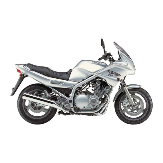
Summary of Contents for Yamaha diversion 900 XJ900S
- Page 1 OWNER’S MANUAL XJ900S 4KM-28199-E7...
- Page 3 EAU03338 Welcome to the Yamaha world of motorcycling! As the owner of an XJ900S, you are benefiting from Yamaha’s vast experience and newest technology regarding the design and manufacture of high-quality products, which have earned Yamaha a reputation for dependability.
- Page 4 This manual should be considered a permanent part of this motorcycle and should remain with it even if the motorcycle is subsequently sold. Yamaha continually seeks advancements in product design and quality. Therefore, while this manual contains the most current product information available at the time of printing, there may be minor discrepancies between your motorcycle and this manual.
-
Page 5: Important Manual Information
IMPORTANT MANUAL INFORMATION EW000002 WARNING PLEASE READ THIS MANUAL CAREFULLY AND COMPLETELY BEFORE OPERATING THIS MOTORCYCLE. - Page 6 IMPORTANT MANUAL INFORMATION EAU04229 XJ900S OWNER’S MANUAL ©2001 by Yamaha Motor Co., Ltd. 1st edition, June 2001 All rights reserved. Any reprinting or unauthorized use without the written permission of Yamaha Motor Co., Ltd. is expressly prohibited. Printed in Japan.
-
Page 7: Table Of Contents
EAU00009 TABLE OF CONTENTS 1 GIVE SAFETY THE RIGHT OF WAY 2 DESCRIPTION 3 INSTRUMENT AND CONTROL FUNCTIONS 4 PRE-OPERATION CHECKS 5 OPERATION AND IMPORTANT RIDING POINTS 6 PERIODIC MAINTENANCE AND MINOR REPAIR 7 MOTORCYCLE CARE AND STORAGE 8 SPECIFICATIONS 9 CONSUMER INFORMATION INDEX... -
Page 9: Give Safety The Right Of Way
GIVE SAFETY THE RIGHT OF WAY GIVE SAFETY THE RIGHT OF WAY ..........1-1... - Page 10 G IVE SAFETY THE RIGHT OF WAY EAU00021 Motorcycles are fascinating vehicles, which can give you an unsurpassed feeling of power and freedom. However, they also impose certain limits, which you must accept; even the best motorcycle does not ignore the laws of physics. Regular care and maintenance are essential for preserving value and operating condition of your motorcycle.
-
Page 11: Description
DESCRIPTION Left view ..................... 2-1 Right view................... 2-2 Controls and instruments ..............2-3... - Page 12 D ESCRIPTION EAU00026 Left view 1. Headlight (page 6-31) 5. Luggage strap holders (page 3-15) 2. Helmet holder (page 3-12) 6. Final gear case (page 6-11) 3. Seat lock (page 3-11) 7. Shock absorber assembly spring 4. Grab bar preload adjusting ring (page 3-14) 8.
- Page 13 DESCRIPTION Right view 9. Tail/brake light (page 6-32) 15. Air filter element (page 6-13) 10. Grab bar 16. Front fork spring preload 11. Fuse box (page 6-30) adjusting bolt (page 3-13) 12. Main fuse (page 6-30) 17. Engine oil level check window (page 6-8) 13.
- Page 14 DESCRIPTION Controls and instruments 1. Clutch lever (page 3-7) 7. Clock (page 3-5) 2. Left handlebar switches (page 3-6) 8. Right handlebar switches (page 3-7) 3. Starter (choke) lever (page 3-11) 9. Brake lever (page 3-8) 4. Speedometer unit (page 3-3) 10.
-
Page 15: Instrument And Control Functions
INSTRUMENT AND CONTROL FUNCTIONS Main switch/steering lock ........3-1 Fuel tank cap ............3-9 Indicator and warning lights ........3-2 Fuel ..............3-9 Speedometer unit ..........3-3 Fuel tank breather hose (for Germany only) ..3-11 Tachometer ............3-4 Starter (choke) lever .......... 3-11 Self-diagnosis device ...........3-4 Seat .............. -
Page 16: Main Switch/Steering Lock
I NSTRUMENT AND CONTROL FUNCTIONS EAU00027 1. Push. 2. Turn. EAU00029 EAU00040 Main switch/steering lock LOCK EW000016 The steering is locked, and all electrical WARNING The main switch/steering lock controls systems are off. The key can be re- the ignition and lighting systems, and is Never turn the key to “OFF”... -
Page 17: Indicator And Warning Lights
6. Right turn signal indicator light “ ” 3. Push the start switch. If the warn- ing light does not come on, have a EAU03034 Indicator and warning lights Yamaha dealer check the electri- cal circuit. EAU04121 Turn signal indicator lights “ ” and “... -
Page 18: Speedometer Unit
Speedometer unit 6. Right turn signal indicator light “ ” pushing the start switch, have a The speedometer unit is equipped with Yamaha dealer check the electri- EAU00061 a speedometer, an odometer and a Neutral indicator light “ ” cal circuit. -
Page 19: Tachometer
If the tachometer displays such an er- Self-diagnosis device ror code, note the circuit-specific num- This model is equipped with a self-di- ber of r/min, and then have a Yamaha agnosis device for the following electri- dealer check the motorcycle. cal circuits:... -
Page 20: Fuel Gauge
INSTRUMENT AND CONTROL FUNCTIONS EAU00109 Anti-theft alarm (optional) This motorcycle can be equipped with an optional anti-theft alarm by a Yamaha dealer. Contact a Yamaha dealer for more information. 1. Fuel gauge 1. Digital clock 2. Minute setting button “M”... -
Page 21: Handlebar Switches
INSTRUMENT AND CONTROL FUNCTIONS The hazard light is used in case of an EAU03888 Dimmer switch “ ” emergency or to warn other drivers Set this switch to “ ” for the high when your motorcycle is stopped beam and to “ ”... -
Page 22: Clutch Lever
INSTRUMENT AND CONTROL FUNCTIONS EAU00143 Start switch “ ” Push this switch to crank the engine with the starter. EC000005 CAUTION: See page 5-1 for starting instruc- tions prior to starting the engine. 1. Engine stop switch “ ” 1. Clutch lever 2. -
Page 23: Shift Pedal
INSTRUMENT AND CONTROL FUNCTIONS 1. Shift pedal 1. Brake lever 1. Brake pedal 2. Brake lever position adjusting nut EAU00157 EAU00162 3. Properly aligned marks Shift pedal Brake pedal a. Adjusting range The shift pedal is located on the left The brake pedal is on the right side of EAU00160 side of the engine and is used in com-... -
Page 24: Fuel Tank Cap
INSTRUMENT AND CONTROL FUNCTIONS 2. Turn the key counterclockwise to the original position, remove it, and then close the lock cover. NOTE: The fuel tank cap cannot be closed un- less the key is in the lock. In addition, the key cannot be removed if the cap is not properly closed and locked. - Page 25 Your Yamaha engine has been de- cial design as the original. signed to use regular unleaded gaso- EAU04284 line with a research octane number of 91 or higher.
-
Page 26: Fuel Tank Breather Hose (For Germany Only)
INSTRUMENT AND CONTROL FUNCTIONS 1. Fuel tank breather hose 1. Starter (choke) lever “ ” 1. Seat lock 2. Unlock. EAU00196 EAU03839 Fuel tank breather hose Starter (choke) lever “ ” EAU02925 Seat (for Germany only) Starting a cold engine requires a richer air-fuel mixture, which is supplied by Before operating the motorcycle: To remove the seat... -
Page 27: Helmet Holder
INSTRUMENT AND CONTROL FUNCTIONS EW000030 WARNING Never ride with a helmet attached to the helmet holder, since the helmet may hit objects, causing loss of control and possibly an accident. To release the helmet from the helmet holder 1. Projection (× 2) 1. -
Page 28: Storage Compartment
Align the appropriate groove on the ad- This storage compartment is designed preload adjusting bolts. justing mechanism with the top of the to hold an optional genuine Yamaha U- EW000035 front fork cap bolt. LOCK. (Other locks may not fit.) When... -
Page 29: Adjusting The Shock Absorber Assembly
INSTRUMENT AND CONTROL FUNCTIONS EAU01671 Adjusting the shock absorber assembly This shock absorber assembly is equipped with a spring preload adjust- ing ring. EC000015 CAUTION: Never attempt to turn an adjusting 1. Spring preload adjusting ring 1. Special wrench mechanism beyond the maximum 2. -
Page 30: Luggage Strap Holders
Do not deform or damage the gas cylinder in any way, as this will result in poor damping per- formance. Always have a Yamaha dealer service the shock absorber. 3-15... -
Page 31: Ignition Circuit Cut-Off System
It cuts the running engine when check this system regularly as de- the transmission is in gear and the scribed below and have a Yamaha sidestand is moved down. dealer repair it if it does not function Periodically check the operation of the properly. - Page 32 5. Push the start switch. Does the engine start? The neutral switch may be defective. The motorcycle should not be ridden until checked by a Yamaha dealer. With the engine still running: 6. Move the sidestand up. 7. Keep the clutch lever pulled.
-
Page 33: Pre-Operation Checks
PRE-OPERATION CHECKS Pre-operation check list ..............4-1... - Page 34 Final gear oil • Check vehicle for oil leakage. 6-11–6-12 • Check operation. • If soft or spongy, have Yamaha dealer bleed hydraulic system. Front brake • Check fluid level in reservoir. 6-22–6-23 • If necessary, add recommended brake fluid to specified level.
- Page 35 • Check operation of ignition circuit cut-off system. Sidestand switch 3-15 • If system is defective, have Yamaha dealer check vehicle. NOTE: Pre-operation checks should be made each time the motorcycle is used. Such an inspection can be accomplished in a very short time;...
-
Page 37: Operation And Important Riding Points
OPERATION AND IMPORTANT RIDING POINTS Starting the engine ................5-1 Starting a warm engine ..............5-3 Shifting ....................5-3 Recommended shift points (for Switzerland only) ......5-4 Tips for reducing fuel consumption ........... 5-4 Engine break-in ................. 5-4 Parking ....................5-5... -
Page 38: Starting The Engine
Before starting engine, are poisonous, and inhaling Yamaha dealer check the electrical cir- check the function of the igni- them can cause loss of con- cuit. tion circuit cut-off system ac- sciousness and death within a 3. - Page 39 Yamaha dealer check the off when the start switch is re- electrical circuit. leased.
-
Page 40: Starting A Warm Engine
OPERATION AND IMPORTANT RIDING POINTS EAU01258 EC000048 Starting a warm engine CAUTION: Follow the same procedure as for start- Even with the transmission in ing a cold engine with the exception the neutral position, do not that the starter (choke) is not required coast for long periods of time when the engine is warm. -
Page 41: Recommended Shift Points (For Switzerland Only)
OPERATION AND IMPORTANT RIDING POINTS EAU02941 EAU00424 EAU01128 Recommended shift points Tips for reducing fuel Engine break-in (for Switzerland only) consumption There is never a more important period in the life of your engine than the period The recommended shift points during Fuel consumption depends largely on between 0 and 1,600 km . -
Page 42: Parking
WARNING period, immediately have a 6,000 r/min. Since the engine and exhaust Yamaha dealer check the vehi- EC000056* system can become very hot, cle. CAUTION: park in a place where pedestri- After 1,000 km of operation, the en-... -
Page 43: Periodic Maintenance And Minor Repair
PERIODIC MAINTENANCE AND MINOR REPAIR Owner’s tool kit ............6-1 Checking and lubricating the throttle grip and cable ............... 6-24 Periodic maintenance and lubrication chart ..6-2 Checking and lubricating the brake and Removing and installing cowlings ......6-5 shift pedals ............6-25 Checking the spark plugs ........6-7 Checking and lubricating the brake and Engine oil and oil filter cartridge ......6-8... -
Page 44: Owner's Tool Kit
Periodic inspection, adjustment and lu- ence required for a particular job, have brication will keep your vehicle in the a Yamaha dealer perform it for you. safest and most efficient condition pos- EW000063 sible. The most important points of in-... -
Page 45: Periodic Maintenance And Lubrication Chart
The annual checks must be performed every year, except if a kilometer-based maintenance is performed instead. From 50,000 km, repeat the maintenance intervals starting from 10,000 km. Items marked with an asterisk should be performed by a Yamaha dealer as they require special tools, data and techni- cal skills. - Page 46 PERIODIC MAINTENANCE AND MINOR REPAIR ODOMETER READING (×1,000 km) ANNUAL ITEM CHECK OR MAINTENANCE JOB CHECK √ √ √ √ Wheels • Check runout and for damage. • Check tread depth and for damage. • Replace if necessary. √ √ √...
- Page 47 PERIODIC MAINTENANCE AND MINOR REPAIR ODOMETER READING (×1,000 km) ANNUAL ITEM CHECK OR MAINTENANCE JOB CHECK Front and rear brake √ √ √ √ √ √ • Check operation. switches √ √ √ √ √ Moving parts and cables • Lubricate. Lights, signals and •...
-
Page 48: Removing And Installing Cowlings
PERIODIC MAINTENANCE AND MINOR REPAIR 1. Cowling A 1. Cowling A 2. Cowling B 2. Screw (× 2) NOTE: EAU01065 EAU03595 Pull the cowling up, then back to re- Removing and installing Cowling A move it. To remove the cowling cowlings 1. - Page 49 PERIODIC MAINTENANCE AND MINOR REPAIR 1. Grab bar 1. Bolt (× 2) 1. Screw (× 2) 2. Cowling B 2. Remove the grab bar by removing 3. Remove the screws, and then pull EAU03596 the bolts. the cowling off as shown. Cowling B To remove the cowling To install the cowling...
-
Page 50: Checking The Spark Plugs
The spark plugs are important engine deposits, it should be replaced. components, which should be checked periodically, preferably by a Yamaha Specified spark plug: dealer. Since heat and deposits will DPR8EA-9 (NGK) or cause any spark plug to slowly erode,... -
Page 51: Engine Oil And Oil Filter Cartridge
PERIODIC MAINTENANCE AND MINOR REPAIR EAU04261 NOTE: Engine oil and oil filter If a torque wrench is not available when cartridge installing a spark plug, a good estimate The engine oil level should be checked of the correct torque is 1/4–1/2 turn before each ride. - Page 52 An oil filter wrench is available at a Skip steps 4–6 if the oil filter cartridge is off. Yamaha dealer. not being replaced. 2. Place an oil pan under the engine to collect the used oil.
- Page 53 PERIODIC MAINTENANCE AND MINOR REPAIR 7. Install the engine oil drain bolt, and ECA00105 CAUTION: then tighten it to the specified In order to prevent clutch slip- torque. page (since the engine oil also lubricates the clutch), do not Tightening torque: mix any chemical additives with Engine oil drain bolt: the oil or use oils of grade “CD”...
-
Page 54: Final Gear Oil
If the oil level warning light flickers terstand. for oil leakage before each ride. If any or remains on, immediately turn the leakage is found, have a Yamaha deal- NOTE: engine off and have a Yamaha deal- The final gear oil level must be er check and repair the motorcycle. - Page 55 PERIODIC MAINTENANCE AND MINOR REPAIR To change the final gear oil NOTE: GL4 is a quality rating. Hypoid gear oils 1. Place an oil pan under the final rated GL5 or GL6 may also be used. gear case to collect the used oil. 2.
-
Page 56: Cleaning The Air Filter Element
PERIODIC MAINTENANCE AND MINOR REPAIR 1. Fuel tank 1. Bolt (× 2) 1. Screw (× 4) 2. Fuel hose 3. Remove the fuel tank bolts. 5. Remove the air filter case cover by 3. Fuel sender coupler 4. Disconnect the fuel sender cou- removing the screws. - Page 57 PERIODIC MAINTENANCE AND MINOR REPAIR EC000082* CAUTION: Make sure that the air filter ele- ment is properly seated in the air filter case. The engine should never be op- erated without the air filter ele- ment installed, otherwise the pistons and/or cylinders may 1.
-
Page 58: Adjusting The Carburetors
Therefore, most car- checked and, if necessary, adjusted as buretor adjustments should be left to a follows at the intervals specified in the Yamaha dealer, who has the neces- periodic maintenance and lubrication sary professional knowledge and expe- chart. -
Page 59: Adjusting The Throttle Cable Free Play
The valve clearance changes with use, resulting in improper air-fuel mixture and/or engine noise. To prevent this from occurring, the valve clearance must be adjusted by a Yamaha dealer at the intervals specified in the periodic maintenance and lubrication chart. a. Throttle cable free play... -
Page 60: Tires
PERIODIC MAINTENANCE AND MINOR REPAIR EAU00658 CE-01E that the total weight of rider, Tire air pressure Tires (measured on cold tires) passenger, cargo, and accesso- To maximize the performance, durabil- Load* Front Rear ries does not exceed the speci- ity, and safe operation of your motor- 225 kPa 250 kPa fied maximum load for the... - Page 61 Yamaha dealer replace the tire immediately. CE-08E Minimum tire tread depth 1.6 mm...
- Page 62 150/70-17 69V After extensive tests, only the Bridgestone G602 conditions. 150/70-17 M/C 69V tires listed below have been ap- CE-14E proved this model FRONT & REAR Yamaha Motor Co., Ltd. Tire air valve TR412 Valve core #9000A (original) 6-19...
-
Page 63: Cast Wheels
If any damage is 1. Locknut 1. Locknut found, have a Yamaha dealer re- 2. Clutch lever free play adjusting bolt 2. Clutch lever free play adjusting nut place the wheel. Do not attempt c. -
Page 64: Adjusting The Brake Pedal Position
If there is air in the hydraulic system, have a Yamaha dealer bleed the system be- fore operating the motorcycle. Air in the hydraulic system will diminish a. Distance between brake pedal and footrest 1. -
Page 65: Checking The Front And Rear Brake Pads
If a brake pad has worn to the point that the wear indicator grooves have almost disappeared, have a Yamaha dealer replace the brake pads as a set. 6-22... -
Page 66: Checking The Brake Fluid Level
A low brake flu- leakage and poor braking perfor- denly, have a Yamaha dealer id level may indicate worn brake pads mance. check the cause. and/or brake system leakage. If the... -
Page 67: Changing The Brake Fluid
EAU02962 EAU04034 Changing the brake fluid Checking and lubricating the Checking and lubricating the Have a Yamaha dealer change the cables throttle grip and cable brake fluid at the intervals specified in The operation of all control cables and The operation of the throttle grip should... -
Page 68: Checking And Lubricating The Brake And Shift Pedals
Recommended lubricant: Recommended lubricant: EW000114 WARNING Lithium-soap-based grease Lithium-soap-based grease If the centerstand or sidestand does (all-purpose grease) (all-purpose grease) not move up and down smoothly, have a Yamaha dealer check or re- pair it. 6-25... -
Page 69: Lubricating The Rear Suspension
PERIODIC MAINTENANCE AND MINOR REPAIR EAU04282 Recommended lubricant: Lubricating the rear Lithium-soap-based grease suspension (all-purpose grease) The pivoting points of the rear suspen- sion must be lubricated at the intervals specified in the periodic maintenance and lubrication chart. Recommended lubricant: Lithium-soap-based grease 6-26... -
Page 70: Checking The Front Fork
EC000098 CAUTION: If any damage is found or the front fork does not operate smoothly, have a Yamaha dealer check or re- pair it. 6-27... -
Page 71: Checking The Wheel Bearings
Yamaha dealer check the wheel bearings. 2. Hold the lower ends of the front fork legs and try to move them for- ward and backward. If any free play can be felt, have a Yamaha dealer check repair steering. -
Page 72: Battery
Avoid any contact with To charge the battery skin, eyes or clothing and al- Have a Yamaha dealer charge the bat- ways shield your eyes when tery as soon as possible if it seems to working near batteries. In case have discharged. -
Page 73: Replacing The Fuses
5. Main fuse cess to a sealed-type (MF) bat- The main fuse and the fuse box, which 6. Spare fuse (× 3) tery charger, have a Yamaha 7. Signaling system fuse contains the fuses for the individual cir- dealer charge your battery. -
Page 74: Replacing The Headlight Bulb
2. Unhook the headlight bulb holder, 4. If the fuse immediately blows EAU04136 and then remove the defective Replacing the headlight bulb again, have a Yamaha dealer bulb. This motorcycle is equipped with a check the electrical system. EW000119 quartz bulb headlight. If the headlight WARNING bulb burns out, replace it as follows. -
Page 75: Replacing The Tail/Brake Light Bulb
CAUTION: and then connect the coupler. Do not overtighten the screws, oth- Do not overtighten the screw, other- 5. Have a Yamaha dealer adjust the erwise the lens may break. wise the lens may break. headlight beam if necessary. 6-32... -
Page 76: Front Wheel
4. Remove the brake calipers by re- EW000122 remove the wheel. moving the bolts. WARNING ECA00047 It is advisable to have a Yamaha CAUTION: dealer service the wheel. Do not pull the brake lever after the Securely support the motor- brake caliper has been removed,... - Page 77 PERIODIC MAINTENANCE AND MINOR REPAIR 5. Install the brake hose holders by installing the bolts. 6. Take the motorcycle off the cen- terstand so that the front wheel is on the ground. 7. Tighten the wheel axle, then the front wheel axle pinch bolt and the brake caliper bolts to the specified torques.
-
Page 78: Rear Wheel
EW000122 3. Remove the brake caliper by re- terstand. WARNING moving the bolts. It is advisable to have a Yamaha 4. Disconnect the brake torque rod dealer service the wheel. from the brake caliper bracket by Securely support the motor-... - Page 79 PERIODIC MAINTENANCE AND MINOR REPAIR ECA00062 4. Connect the brake torque rod to CAUTION: the brake caliper bracket by in- Do not push the brake pedal after stalling the bolt and the nut. the wheel has been removed togeth- 5. Install the axle nut, and then slight- er with the brake disc, otherwise the ly tighten it.
-
Page 80: Troubleshooting
However, should your motorcycle require any repair, take it to a Yamaha dealer, whose skilled technicians have the necessary tools, experience, and know-how to service the motorcycle properly. -
Page 81: Troubleshooting Chart
Remove the spark plugs and check the electrodes. The engine does not start. Have a Yamaha dealer check the vehicle. Check the battery. 4. Battery The engine turns over The battery is good. -
Page 83: Motorcycle Care And Storage
MOTORCYCLE CARE AND STORAGE Care ....................7-1 Storage ....................7-4... - Page 84 M OTORCYCLE CARE AND STORAGE EAU03412 Care Before cleaning Cleaning 1. Cover the muffler outlets with plas- ECA00010 While the open design of a motorcycle CAUTION: tic bags after the engine has reveals the attractiveness of the tech- Avoid using strong acidic wheel cooled down.
- Page 85 MOTORCYCLE CARE AND STORAGE Do not use any harsh chemical For motorcycles equipped with After riding in the rain, near the sea or products on plastic parts. Be a windshield: Do not use strong on salt-sprayed roads sure to avoid using cloths or cleaners or hard sponges as Since sea salt or salt sprayed on roads sponges which have been in...
- Page 86 NOTE: including chrome- and nickel-plat- Consult a Yamaha dealer for advice on ed, surfaces. what products to use. 4. Use spray oil as a universal clean- er to remove any remaining dirt. 5. Touch up minor paint damage caused by stones, etc.
- Page 87 MOTORCYCLE CARE AND STORAGE Storage Long-term a. Remove the spark plug caps and Before storing your motorcycle for spark plugs. several months: b. Pour a teaspoonful of engine oil Short-term 1. Follow all the instructions in the into each spark plug bore. Always store your motorcycle in a cool, “Care”...
- Page 88 MOTORCYCLE CARE AND STORAGE 6. Lubricate all control cables and NOTE: Make any necessary repairs before the pivoting points of all levers and storing the motorcycle. pedals as well as of the sidestand/ centerstand. 7. Check and, if necessary, correct the tire air pressure, and then lift the motorcycle so that both of its wheels are off the ground.
-
Page 89: Specifications
SPECIFICATIONS Specifications ..................8-1 Conversion table ................8-5... - Page 90 S PECIFICATIONS EAU01038 Specifications CS-01E Model XJ900S Engine oil Dimensions Type -20 -10 10 20 30 40 50 ˚C Overall length 2,230 mm SAE 10W-30 Overall width 750 mm SAE 10W-40 Overall height 1,300 mm Seat height 795 mm SAE 15W-40 Wheelbase 1,505 mm SAE 20W-40...
- Page 91 SPECIFICATIONS Final gear oil Operation Left foot Type Hypoid gear oil SAE 80 (API GL4) Gear ratio or multi-grade hypoid gear oil 2.188 SAE 80W-90 1.500 Quantity 0.2 L 1.154 Air filter Dry element 0.933 Fuel 0.813 Type REGULAR UNLEADED Chassis GASOLINE ONLY Frame type...
- Page 92 SPECIFICATIONS Manufacturer/ Brakes model Dunlop / K505 Front Metzeler / ME55A Type Dual disc brake Bridgestone / G602 Operation Right hand Maximum load* 205 kg Fluid DOT 4 Tire air pressure (measured Rear on cold tires) Type Single disc brake up to 90 kg* Operation Right foot...
- Page 93 SPECIFICATIONS Voltage, capacity 12 V, 12 Ah Headlight type Quartz bulb (halogen) Bulb voltage, wattage × quantity 12 V, 60/55 W × 1 Headlight 12 V, 5/21 W × 1 Tail/brake light 12 V, 4 W × 1 Auxiliary light 12 V, 21 W ×...
-
Page 94: Conversion Table
SPECIFICATIONS EAU03941 Conversion table Conversion table METRIC SYSTEM TO IMPERIAL SYSTEM CS-03E Metric unit Conversion factor Imperial unit All specification data in this manual are listed in SI and × m·kgf 7.233 ft·lb × METRIC UNITS. m·kgf 86.794 in·lb Torque ×... -
Page 95: Consumer Information
CONSUMER INFORMATION Identification numbers ............... 9-1 Key identification number ..............9-1 Vehicle identification number ............. 9-1 Model label ..................9-2... - Page 96 Record the key identification number, vehicle identification number and mod- el label information in the spaces pro- vided below for assistance when ordering spare parts from a Yamaha dealer or for reference in case the vehi- cle is stolen. 1. Key identification number 1.
- Page 97 The model label is affixed to the frame under the seat. (See page 3-11 for seat removal and installation procedures.) Record the information on this label in the space provided. This information will be needed when ordering spare parts from a Yamaha dealer.
- Page 98 I NDEX 1 0 - Engine oil and oil filter cartridge ....6-8 Luggage strap holders ......3-15 Engine stop switch........3-7 Air filter element, cleaning ......6-13 Anti-theft alarm ........3-5 Main switch/steering lock ......3-1 Final gear oil.......... 6-11 Model label ..........9-2 Front fork, adjusting.......
- Page 99 INDEX Starting a warm engine......5-3 Starting the engine ........5-1 Start switch..........3-7 Steering, checking ......... 6-27 Storage............ 7-4 Storage compartment ......3-13 Tachometer ..........3-4 Tail/brake light bulb, replacing ....6-32 Throttle cable free play, adjusting ..6-16 Throttle grip and cable, checking and lubricating..........
- Page 102 YAMAHA MOTOR CO., LTD. PRINTED ON RECYCLED PAPER PRINTED IN JAPAN 2001 . 7 - 0.3 × 1 CR...