Table of Contents
Advertisement
Advertisement
Chapters
Table of Contents
Troubleshooting

Related Manuals for Yamaha Diversion XJ600N


Summary of Contents for Yamaha Diversion XJ600N
- Page 1 OWNER’S MANUAL XJ600S 4BR-28199-E7...
- Page 3 In addition, the many tips given in this manual will help keep your motorcycle in the best possible condition. If you have any further questions, do not hesitate to contact your Yamaha dealer. The Yamaha team wishes you many safe and pleasant rides. So, remember to put safety first!
- Page 4 This manual should be considered a permanent part of this motorcycle and should remain with it even if the motorcycle is subsequently sold. Yamaha continually seeks advancements in product design and quality. Therefore, while this manual contains the most current product information available at the time of printing, there may be minor discrepancies between your motorcycle and this manual.
-
Page 5: Important Manual Information
IMPORTANT MANUAL INFORMATION EW000002 WARNING PLEASE READ THIS MANUAL CAREFULLY AND COMPLETELY BEFORE OPERATING THIS MOTORCYCLE. - Page 6 IMPORTANT MANUAL INFORMATION EAU03337 XJ600S/XJ600N OWNER’S MANUAL © 2000 by Yamaha Motor Co., Ltd. 1st Edition, May 2000 All rights reserved. Any reprinting or unauthorized use without the written permission of Yamaha Motor Co., Ltd. is expressly prohibited. Printed in Japan.
-
Page 7: Table Of Contents
EAU00009 TABLE OF CONTENTS 1 GIVE SAFETY THE RIGHT OF WAY 2 DESCRIPTION 3 INSTRUMENT AND CONTROL FUNCTIONS 4 PRE-OPERATION CHECKS 5 OPERATION AND IMPORTANT RIDING POINTS 6 PERIODIC MAINTENANCE AND MINOR REPAIR 7 MOTORCYCLE CARE AND STORAGE 8 SPECIFICATIONS 9 CONSUMER INFORMATION INDEX... -
Page 9: Give Safety The Right Of Way
GIVE SAFETY THE RIGHT OF WAY GIVE SAFETY THE RIGHT OF WAY ..........1-1... - Page 10 G IVE SAFETY THE RIGHT OF WAY EAU00021 Motorcycles are fascinating vehicles, which can give you an unsurpassed feeling of power and freedom. However, they also impose certain limits, which you must accept; even the best motorcycle does not ignore the laws of physics. Regular care and maintenance are essential for preserving value and operating condition of your motorcycle.
-
Page 11: Description
DESCRIPTION Left view (XJ600S) ................2-1 Right view (XJ600S)................2-2 Controls and instruments (XJ600S) ........... 2-3 Left view (XJ600N) ................2-4 Right view (XJ600N) ................2-5 Controls and instruments (XJ600N) ........... 2-6... -
Page 12: Left View (Xj600S)
D ESCRIPTION EAU00026 Left view (XJ600S) 1. Fuel cock (page 3-11) 6. Rear shock absorber spring 2. Helmet holder (page 3-13) preload adjusting ring (page 3-14) 3. Fuse box (page 6-29) 7. Shift pedal (page 3-8) 4. Luggage strap holders (page 3-15) 5. -
Page 13: Right View (Xj600S)
DESCRIPTION Right view (XJ600S) 8. Tail/brake light 9. Storage compartment (page 3-13) 10. Seat (page 3-12) 11. Fuel tank (page 3-9) 12. Headlight (page 6-30) 13. Brake pedal (page 3-9) -
Page 14: Controls And Instruments (Xj600S)
DESCRIPTION Controls and instruments (XJ600S) 14. Clutch lever (page 3-7) 15. Left handlebar switches (page 3-6) 16. Starter (choke) lever (page 3-12) 17. Speedometer unit (page 3-4) 18. Tachometer (page 3-5) 19. Right handlebar switches (page 3-7) 20. Brake lever (page 3-8) 21. -
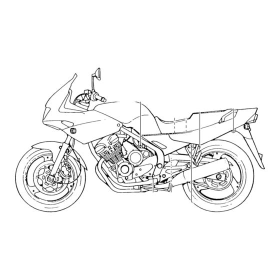
Page 15: Left View (Xj600N)
DESCRIPTION Left view (XJ600N) 1. Steering lock (page 3-3) 6. Seat lock (page 3-12) 2. Fuel cock (page 3-11) 7. Rear shock absorber spring preload 3. Helmet holder (page 3-13) adjusting ring (page 3-14) 4. Fuse box (page 6-29) 8. Shift pedal (page 3-8) 5. -
Page 16: Right View (Xj600N)
DESCRIPTION Right view (XJ600N) 9. Tail/brake light 10. Storage compartment (page 3-13) 11. Seat (page 3-12) 12. Fuel tank (page 3-9) 13. Headlight (page 6-30) 14. Brake pedal (page 3-9) -
Page 17: Controls And Instruments (Xj600N)
DESCRIPTION Controls and instruments (XJ600N) 15. Clutch lever (page 3-7) 16. Left handlebar switches (page 3-6) 17. Starter (choke) lever (page 3-12) 18. Speedometer unit (page 3-5) 19. Tachometer (page 3-5) 20. Right handlebar switches (page 3-7) 21. Brake lever (page 3-8) 22. -
Page 19: Instrument And Control Functions
INSTRUMENT AND CONTROL FUNCTIONS Main switch/steering lock ........3-1 Fuel ..............3-10 Steering lock (for XJ600N)........3-3 Fuel tank breather hose (for Germany only) ..3-10 Indicator lights .............3-3 Fuel cock ............3-11 Speedometer unit (for XJ600S) ......3-4 Starter (choke) lever .......... 3-12 Speedometer unit (for XJ600N) ......3-5 Seat .............. -
Page 20: Main Switch/Steering Lock
I NSTRUMENT AND CONTROL FUNCTIONS EAU00027 XJ600S XJ600N EAU00029 EAU00038 EAU00040 Main switch/steering lock LOCK (for XJ600S) All electrical systems are off. The key The steering is locked, and all electrical The main switch/steering lock controls can be removed. systems are off. The key can be re- the ignition and lighting systems, and is moved. -
Page 21: Instrument And Control Functions
INSTRUMENT AND CONTROL FUNCTIONS EW000016 XJ600S XJ600N WARNING Never turn the key to “OFF” or “LOCK” while the motorcycle is moving, otherwise the electrical systems will be switched off, which may result in loss of control or an accident. Make sure that the motor- cycle is stopped before turning the 1. -
Page 22: Steering Lock (For Xj600N)
INSTRUMENT AND CONTROL FUNCTIONS To unlock the steering XJ600S 1. Open the steering lock cover, and then insert the key. 2. Push the key in, turn it 1/8 turn counterclockwise so that it moves out, and then release it. 3. Remove the key, and then close the lock cover. -
Page 23: Speedometer Unit (For Xj600S)
3. Push the start switch. If the warn- ing light does not come on while pushing the start switch, have a Yamaha dealer check the electri- cal circuit. 1. Neutral indicator light “ ”... -
Page 24: Speedometer Unit (For Xj600N)
INSTRUMENT AND CONTROL FUNCTIONS XJ600N XJ600S XJ600N 1. Speedometer 1. Tachometer 1. Tachometer 2. Odometer 2. Red zone (except for CH, A) 2. Red zone (except for CH, A) 3. Tripmeter 3. Red zone (for CH, A) 3. Red zone (for CH, A) 4. -
Page 25: Handlebar Switches
INSTRUMENT AND CONTROL FUNCTIONS EAU00144 EAU00127 Hazard switch “ ” Turn signal switch With the key in the “ON” or “P” position, To signal a right-hand turn, push this use this switch to turn on the hazard switch to “ ”. -
Page 26: Clutch Lever
INSTRUMENT AND CONTROL FUNCTIONS EAU00143 Start switch “ ” Push this switch to crank the engine with the starter. EC000005 CAUTION: See page 5-1 for starting instruc- tions prior to starting the engine. 1. Engine stop switch 1. Clutch lever 2. -
Page 27: Shift Pedal
INSTRUMENT AND CONTROL FUNCTIONS 1. Shift pedal 1. Brake lever 1. Brake lever position adjusting nut 2. Position adjusting nut 2. Properly aligned marks EAU00157 Shift pedal The brake lever is equipped with a po- EAU00160 Brake lever The shift pedal is located on the left sition adjusting nut. -
Page 28: Brake Pedal
INSTRUMENT AND CONTROL FUNCTIONS NOTE: The fuel tank cap cannot be closed un- less the key is in the lock. In addition, the key cannot be removed if the cap is not properly closed and locked. EWA00025 WARNING Make sure that the fuel tank cap is properly closed before riding. -
Page 29: Fuel
INSTRUMENT AND CONTROL FUNCTIONS EAU00185 CAUTION: Immediately wipe off spilled fuel with a clean, dry, soft cloth, since fuel may deteriorate painted surfac- es or plastic parts. EAU00191 Recommended fuel: 1. Fuel tank filler tube 1. Fuel tank breather hose Regular unleaded gasoline with a 2. -
Page 30: Fuel Cock
INSTRUMENT AND CONTROL FUNCTIONS Normal position Reserve position Prime position 1. Arrow mark positioned over “ON” 1. Arrow mark positioned over “RES” 1. Arrow mark positioned over “PRI” EAU00207 Fuel cock This indicates reserve. With the fuel This indicates prime. With the fuel cock The fuel cock supplies fuel from the cock lever in this position, the fuel re- lever in this position, the engine can be... -
Page 31: Starter (Choke) Lever
INSTRUMENT AND CONTROL FUNCTIONS 1. Starter (choke) lever 1. Unlock. 1. Projection ( 2) 2. Seat holder EAU02976 EAU02925 Starter (choke) lever Seat To install the seat Starting a cold engine requires a richer Insert the projections on the front of the air-fuel mixture, which is supplied by To remove the seat seat into the seat holder, push the rear... -
Page 32: Helmet Holders
The helmet holders are located under This storage compartment is designed the seat. to hold a genuine Yamaha U-LOCK. (Other locks may not fit.) When placing To secure a helmet to a helmet holder a U-LOCK in the storage compartment, 1. -
Page 33: Adjusting The Shock Absorber Assembly
CI-01E Always have a Yamaha dealer Minimum Stan- Maximum (hard) service the shock absorber. (soft) dard... -
Page 34: Luggage Strap Holders
Therefore, et and one below each side of the seat. check this system regularly as de- scribed below and have a Yamaha dealer repair it if it does not function properly. 3-15... -
Page 35: Ignition Circuit Cut-Off System
If a malfunction is noted, have a It prevents starting when the trans- Yamaha dealer check the sys- mission is in gear and the side- tem before riding. stand is up, but the clutch lever is not pulled. - Page 36 5. Push the start switch. Does the engine start? The neutral switch may be defective. The motorcycle should not be ridden until checked by a Yamaha dealer. With the engine still running: 6. Move the sidestand up. 7. Keep the clutch lever pulled.
-
Page 37: Pre-Operation Checks
PRE-OPERATION CHECKS Pre-operation check list ..............4-1... -
Page 38: Pre-Operation Check List
P RE-OPERATION CHECKS EAU01114 The condition of a vehicle is the owner’s responsibility. Vital components can start to deteriorate quickly and unexpectedly, even if the vehicle remains unused (for example, as a result of exposure to the elements). Any damage, fluid leakage or loss of tire air pressure could have serious consequences. - Page 39 PRE-OPERATION CHECKS ITEM CHECKS PAGE • Make sure that all nuts, bolts and screws are properly tightened. Chassis fasteners — • Tighten if necessary. • Check fuel level. Fuel 3-9–3-10 • Fill with fuel if necessary. Lights, signals and • Check proper operation. —...
-
Page 41: Operation And Important Riding Points
OPERATION AND IMPORTANT RIDING POINTS Starting a cold engine ............... 5-1 Starting a warm engine ..............5-2 Shifting ....................5-3 Recommended shift points (for Switzerland only) ......5-3 Tips for reducing fuel consumption ........... 5-4 Engine break-in ................. 5-4 Parking ....................5-5... -
Page 42: Starting A Cold Engine
Yamaha dealer check the electrical The transmission is in the neutral Consult a Yamaha dealer re- circuit. position. -
Page 43: Starting A Warm Engine
If the warning light does not come on when pushing the start switch, or if it does not go off after starting with sufficient engine oil, have a Yamaha dealer check the electrical circuit. 6. After starting the engine, move the starter (choke) knob/lever back... -
Page 44: Shifting
OPERATION AND IMPORTANT RIDING POINTS EC000048 EAU02937 Recommended shift points CAUTION: (for Switzerland only) Even with the transmission in The recommended shift points during the neutral position, do not acceleration are shown in the table coast for long periods of time below. -
Page 45: Tips For Reducing Fuel Consumption
OPERATION AND IMPORTANT RIDING POINTS EAU00424 EAU00436 EAU00440 Tips for reducing fuel Engine break-in 0–150 km Avoid prolonged operation above consumption There is never a more important period 5,000 r/min. in the life of your engine than the period Fuel consumption depends largely on After every hour of operation, stop between 0 and 1,000 km. -
Page 46: Parking
The vehicle can now be operated soft ground, otherwise normally. motorcycle may overturn. EC000053 CAUTION: Keep the engine speed out of the tachometer red zone. If any engine trouble should oc- cur during the engine break-in period, immediately have a Yamaha dealer check vehicle. -
Page 47: Periodic Maintenance And Minor Repair
PERIODIC MAINTENANCE AND MINOR REPAIR Owner’s tool kit ............6-1 Checking and lubricating the throttle grip and cable ............... 6-24 Periodic maintenance and lubrication chart ..6-2 Checking and lubricating the brake and Removing and installing the panel .......6-5 shift pedals ............6-24 Checking the spark plugs ........6-6 Checking and lubricating the brake and Engine oil and oil filter cartridge ......6-7... -
Page 48: Owner's Tool Kit
If you are not familiar with motor- NOTE: cycle maintenance work, have a If you do not have the tools or experi- Yamaha dealer do it for you. ence required for a particular job, have a Yamaha dealer perform it for you. -
Page 49: Periodic Maintenance And Minor Repair
The annual checks must be performed every year, except if a kilometer-based maintenance is performed instead. From 50,000 km, repeat the maintenance intervals starting from 10,000 km. Items marked with an asterisk should be performed by a Yamaha dealer as they require special tools, data and techni- cal skills. - Page 50 PERIODIC MAINTENANCE AND MINOR REPAIR ODOMETER READING ( 1,000 km) Annual ITEM CHECK OR MAINTENANCE JOB check Wheels • Check runout and for damage. • Check tread depth and for damage. • Replace if necessary. Tires • Check air pressure. •...
- Page 51 PERIODIC MAINTENANCE AND MINOR REPAIR ODOMETER READING ( 1,000 km) Annual ITEM CHECK OR MAINTENANCE JOB check Front and rear brake • Check operation. switches Moving parts and cables • Lubricate. Lights, signals and • Check operation. switches • Adjust headlight beam. EAU03884 NOTE: The air filter needs more frequent service if you are riding in unusually wet or dusty areas.
-
Page 52: Removing And Installing The Panel
PERIODIC MAINTENANCE AND MINOR REPAIR 1. Panel A 1. Screw ( 2) EAU01777 EAU02926 Removing and installing the Panel A panel To remove the panel The panel shown above needs to be 1. Remove the seat. (See page 3-12 removed to perform some of the main- for seat removal and installation tenance jobs described in this chapter. -
Page 53: Checking The Spark Plugs
Spark plug gap problems yourself. Instead, have a To install the panel EAU01880 Yamaha dealer check the motorcycle. Checking the spark plugs 1. Place the panel in the original po- If a spark plug shows signs of electrode The spark plugs are important engine sition, and then install the screws. -
Page 54: Engine Oil And Oil Filter Cartridge
PERIODIC MAINTENANCE AND MINOR REPAIR Clean the surface of the spark plug NOTE: Make sure that the motorcycle is posi- gasket and its mating surface, and then tioned straight up when checking the oil wipe off any grime from the spark plug level. - Page 55 An oil filter wrench is available at a Skip steps 4–6 if the oil filter cartridge is off. Yamaha dealer. not being replaced. 2. Place an oil pan under the engine to collect the used oil.
- Page 56 PERIODIC MAINTENANCE AND MINOR REPAIR 8. Add the specified amount of the recommended engine oil, and then install and tighten the oil filler cap. Recommended engine oil: See page 8-1. Oil quantity: Without oil filter cartridge 1. O-ring 1. Torque wrench replacement: 5.
-
Page 57: Cleaning The Air Filter Element
(since the engine oil also or remains on, immediately turn the lubricates the clutch), do not engine off and have a Yamaha deal- mix any chemical additives with er check the vehicle. the oil or use oils of a higher 10. - Page 58 PERIODIC MAINTENANCE AND MINOR REPAIR 1. Fuel hose 1. Screw ( 4) 2. Vacuum hose 4. Remove the fuel tank by removing 5. Remove the air filter case cover by 3. Fuel tank drain hose the bolts. removing the screws. 3.
-
Page 59: Adjusting The Carburetors
Therefore, most car- air filter case. buretor adjustments should be left to a The engine should never be op- Yamaha dealer, who has the neces- erated without the air filter ele- sary professional knowledge and expe- ment installed, otherwise the rience. -
Page 60: Adjusting The Engine Idling Speed
Yamaha dealer adjust it. Engine idling speed: 1,200 – 1,300 r/min NOTE: If the specified idling speed cannot be obtained as described above, have a Yamaha dealer make the adjustment. 6-13... -
Page 61: Adjusting The Valve Clearance
2.00 bar 2.25 bar from occurring, the valve clearance regarding the specified tires. 200 kPa 250 kPa must be adjusted by a Yamaha dealer 90 kg–maximum 2.00 kg/cm 2.50 kg/cm 2.00 bar 2.50 bar at the intervals specified in the periodic... - Page 62 Yamaha dealer fied maximum load for the replace the tire immediately. vehicle.
- Page 63 PERIODIC MAINTENANCE AND MINOR REPAIR EW000079 Tire information EAU00683 WARNING WARNING This motorcycle is equipped with tube Have a Yamaha dealer replace Have a Yamaha dealer replace tires. excessively worn tires. Besides excessively worn tires. Besides EW000078 WARNING being illegal,...
-
Page 64: Wheels
If any damage is 1. Clutch lever free play locknut 1. Clutch lever cable found, have a Yamaha dealer re- 2. Clutch lever free play adjusting bolt 2. Clutch lever free play adjusting nut place the wheel. Do not attempt c. -
Page 65: Adjusting The Brake Pedal Position
If there is air in the hydraulic system, have a Yamaha dealer bleed the system be- fore operating the motorcycle. Air in the hydraulic system will diminish a. Distance between brake pedal and footrest... -
Page 66: Adjusting The Rear Brake Light Switch
Yamaha dealer replace Turn the adjusting nut while holding the the brake pads as a set. rear brake light switch in place. To make the brake light come on earlier, turn the adjusting nut in direction a. -
Page 67: Checking The Brake Fluid Level
If the mance. touches the brake disc, have a brake level is low, be sure to check the Yamaha dealer replace the brake pads brake pads for wear and the brake sys- Recommended brake fluid: DOT 4 as a set. -
Page 68: Changing The Brake Fluid
Be careful that water does not en- EAU03238 Changing the brake fluid ter the master cylinder when refill- Have a Yamaha dealer change the ing. Water will significantly lower brake fluid at the intervals specified in the boiling point of the fluid and the periodic maintenance and lubrica- may result in vapor lock. - Page 69 PERIODIC MAINTENANCE AND MINOR REPAIR NOTE: Drive chain slack: Using the alignment marks on each 30–40 mm side of the swingarm, make sure that both adjusting nuts are in the same po- 5. If the drive chain slack is incorrect, sition for proper wheel alignment.
-
Page 70: Lubricating The Drive Chain
EC000097 Yamaha dealer check or replace it. could damage the O-rings. CAUTION: The drive chain must be lubricated Recommended lubricant: after washing the motorcycle or Engine oil riding in the rain. -
Page 71: Checking And Lubricating The Throttle Grip And Cable
PERIODIC MAINTENANCE AND MINOR REPAIR EAU03209 EAU03370 Checking and lubricating the Recommended lubricant: Checking and lubricating the Throttle cable: throttle grip and cable brake and shift pedals Engine oil The operation of the throttle grip and The operation of the brake and shift Throttle grip housing and grip: the condition of the throttle cable pedals should be checked before each... -
Page 72: Checking And Lubricating The Brake And Clutch Levers
Recommended lubricant: EW000114 Recommended lubricant: WARNING Lithium-soap-based grease Molybdenum disulfide grease If the centerstand or sidestand does (all-purpose grease) not move up and down smoothly, have a Yamaha dealer check or re- pair it. Recommended lubricant: Lithium-soap-based grease (all-purpose grease) 6-25... -
Page 73: Checking The Front Fork
EC000098 CAUTION: If any damage is found or the front fork does not operate smoothly, have a Yamaha dealer check or re- pair it. 6-26... -
Page 74: Checking The Wheel Bearings
2. Hold the lower ends of the front ly damage the battery. fork legs and try to move them for- ward and backward. If any free EW000116 play can be felt, have a Yamaha WARNING dealer check or repair the steer- Electrolyte is poisonous and ing. - Page 75 PERIODIC MAINTENANCE AND MINOR REPAIR • EXTERNAL: Flush with plenty To charge the battery EC000102 CAUTION: of water. Have a Yamaha dealer charge the bat- Always keep battery • INTERNAL: Drink large quan- tery as soon as possible if it seems to charged.
-
Page 76: Replacing The Fuses
3. Signaling system fuse Replacing the fuses 4. If the fuse immediately blows 4. Headlight fuse again, have a Yamaha dealer The fuse box is located under the seat. 5. Hazard fuse check the electrical system. 6. Spare fuse ( 3) (See page 3-12 for seat removal and installation procedures.) -
Page 77: Replacing A Headlight Bulb (For Xj600S)
PERIODIC MAINTENANCE AND MINOR REPAIR 1. Headlight coupler 1. Headlight bulb holder 1. Do not touch this area. 2. Headlight bulb cover 2. Unhook the headlight bulb holder, 3. Place a new bulb into position, and EAU00829 and then remove the defective then secure it with the bulb holder. -
Page 78: Replacing The Headlight Bulb (For Xj600N)
PERIODIC MAINTENANCE AND MINOR REPAIR 4. Install the bulb cover, and then connect the coupler. 5. Have a Yamaha dealer adjust the headlight beam if necessary. 1. Screw ( 2) 1. Headlight coupler 2. Headlight bulb cover EAU03188 Replacing the headlight bulb 2. - Page 79 5. Install the bulb cover, and then connect the coupler. 6. Install the headlight unit by install- ing the screws. 7. Have a Yamaha dealer adjust the headlight beam if necessary. 1. Headlight bulb holder 1. Do not touch this area.
-
Page 80: Front Wheel
2. Lift the wheel up between the fork WARNING otherwise the brake pads will be legs. It is advisable to have a Yamaha forced shut. dealer service the wheel. 4. Loosen the front wheel axle pinch NOTE:... - Page 81 PERIODIC MAINTENANCE AND MINOR REPAIR Tightening torques: Wheel axle: 58 Nm (5.8 m·kg) Front wheel axle pinch bolt: 40 Nm (4.0 m·kg) Brake caliper bolt: 19 Nm (1.9 m·kg) 7. Connect the speedometer cable. 8. Push down hard on the handlebar 5.
-
Page 82: Rear Wheel
EW000122 rear sprocket. WARNING NOTE: It is advisable to have a Yamaha The drive chain does not need to be dealer service the wheel. disassembled in order to remove and Securely support the motor- install the rear wheel. -
Page 83: Troubleshooting
4. Install the brake caliper by install- self. However, should your motorcycle ing the bolts. require any repair, take it to a Yamaha dealer, whose skilled technicians have NOTE: the necessary tools, experience, and... -
Page 84: Troubleshooting Chart
Remove the spark plugs and check the electrodes. The engine does not start. Have a Yamaha dealer check the vehicle. Check the battery. 4. Battery The engine turns over The battery is good. -
Page 85: Motorcycle Care And Storage
MOTORCYCLE CARE AND STORAGE Care ....................7-1 Storage ....................7-4... - Page 86 M OTORCYCLE CARE AND STORAGE EAU03430 Care Before cleaning Cleaning 1. Cover the muffler outlets with plas- ECA00010 While the open design of a motorcycle CAUTION: tic bags after the engine has reveals the attractiveness of the tech- Avoid using strong acidic wheel cooled down.
-
Page 87: Motorcycle Care And Storage
MOTORCYCLE CARE AND STORAGE Do not use any harsh chemical For motorcycles equipped with After riding in the rain, near the sea or products on plastic parts. Be a windshield: Do not use strong on salt-sprayed roads sure to avoid using cloths or cleaners or hard sponges as Since sea salt or salt sprayed on roads sponges which have been in... - Page 88 NOTE: 4. To prevent corrosion, it is recom- Consult a Yamaha dealer for advice on mended to apply a corrosion pro- what products to use. tection spray...
- Page 89 MOTORCYCLE CARE AND STORAGE Storage Long-term c. Install the spark plug caps onto the Before storing your motorcycle for spark plugs, and then place the several months: spark plugs on the cylinder head Short-term 1. Follow all the instructions in the so that the electrodes are ground- Always store your motorcycle in a cool, “Care”...
- Page 90 MOTORCYCLE CARE AND STORAGE 7. Check and, if necessary, correct the tire air pressure, and then lift the motorcycle so that both of its wheels are off the ground. Alterna- tively, turn the wheels a little every month in order to prevent the tires from becoming degraded in one spot.
-
Page 91: Specifications
SPECIFICATIONS Specifications ..................8-1 Conversion table ................8-5... - Page 92 S PECIFICATIONS EAU01038 Specifications CS-01E Model XJ600S/XJ600N Engine oil Dimensions Type -20 -10 10 20 30 40 50 ˚C Overall length 2,170 mm SAE 10W–30 Overall width 735 mm Overall height SAE 10W–40 XJ600S 1,205 mm SAE 15W–40 XJ600N 1,090 mm SAE 20W–40 Seat hight 770 mm...
- Page 93 SPECIFICATIONS Air filter Dry type element Operation Left foot Fuel Gear ratio Type Regular unleaded gasoline 2.733 Fuel tank capacity 17.0 L 1.778 Reserve amount 3.5 L 1.333 Carburetor 1.074 Manufacturer MIKUNI 0.913 Model quantity BDS28 0.821 Spark plug Chassis Model/Manufacturer CR8E / NGK Frame type...
- Page 94 SPECIFICATIONS Maximum load* Brakes XJ600S 184 kg Front XJ600N 187 kg Type Dual disc brake Tire air pressure (measured on Operation Right hand cold tires) Fluid DOT 4 Up to 90 kg* Rear Front 200 kPa (2.00 kg/cm , 2.00 bar) Type Single disc brake Rear...
- Page 95 SPECIFICATIONS Charging system Fuses Type A.C. magneto Main fuse 30 A Standard output 14 V, 20 A @ 5,000 r/min Ignition fuse 10 A Battery Signaling system fuse 15 A Model YTX9-BS Headlight fuse 15 A Voltage, capacity 12 V, 8 Ah Hazard fuse 10 A Headlight type...
-
Page 96: Conversion Table
SPECIFICATIONS EAU01064 Conversion table CS-02E Conversion table All specification data in this manual are listed in SI and METRIC TO IMPERIAL METRIC UNITS. Metric unit Multiplier Imperial unit Use this table to convert METRIC unit data to IMPERIAL m·kg 7.233 ft·lb m·kg 86.794... -
Page 97: Consumer Information
CONSUMER INFORMATION Identification numbers ............... 9-1 Key identification number (for XJ600S) ..........9-1 Key identification number (for XJ600N)..........9-1 Vehicle identification number ............. 9-2 Model label ..................9-2... -
Page 98: Identification Numbers
Record the key identification number, vehicle identification number and mod- el label information in the spaces pro- vided below for assistance when ordering spare parts from a Yamaha dealer or for reference in case the vehi- cle is stolen. 1. Key identification number 1. -
Page 99: Consumer Information
This information NOTE: will be needed when ordering spare The vehicle identification number is parts from a Yamaha dealer. used to identify your motorcycle and may be used to register your motor- cycle with the licensing authority in... - Page 100 I NDEX 1 0 - Drive chain slack ........6-21 Ignition circuit cut-off system ....3-16 Adjusting .......... 6-22 Indicator lights..........3-3 Air filter element, cleaning ......6-10 Checking.......... 6-21 Key identification number (for XJ600N) ..9-1 Battery ...........6-27 Engine break-in ........5-4 Key identification number (for XJ600S) ..9-1 Brake and clutch levers, checking and Engine oil and oil filter cartridge ....
- Page 101 INDEX Right view (XJ600N)........ 2-5 Turn signal indicator lights....... 3-3 Right view (XJ600S) ........ 2-2 Turn signal switch ........3-6 Safety information........1-1 Valve clearance, adjusting ....6-14 Seat............3-12 Vehicle identification number....9-2 Shifting ............ 5-3 Shift pedal ..........3-8 Wheel bearings, checking .....
- Page 104 YAMAHA MOTOR CO., LTD. PRINTED ON RECYCLED PAPER PRINTED IN JAPAN 2000 · 5 - 0.3 3 CR...