Toro 03806 Operator's Manual
Traction unit
Hide thumbs
Also See for 03806:
- Operator's manual (60 pages) ,
- Operator's manual (64 pages) ,
- Service manual (328 pages)
Table of Contents
Advertisement
Quick Links
Download this manual
See also:
Operator's Manual
Advertisement
Table of Contents

Related Manuals for Toro 03806


Summary of Contents for Toro 03806
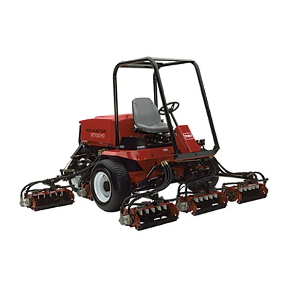
- Page 1 Form No. 3358-628 Rev A Reelmaster® 6500-D and 6700-D Traction Unit Model No. 03806—Serial No. 270000001 and Up Model No. 03807—Serial No. 270000001 and Up Model No. 03808—Serial No. 270000001 and Up Register at www.Toro.com. Original Instructions (EN)
-
Page 2: Introduction
You are responsible for operating the product properly and safely. You may contact Toro directly at www.Toro.com for product and accessory information, help finding a dealer, or to register your product. -
Page 3: Table Of Contents
Battery Care ............41 Safety ................4 Fuses..............41 Safe Operating Practices ........4 Optional Lighting..........42 Toro Mower Safety ..........5 Drive System Maintenance ........43 Sound Pressure Level ........... 6 Checking the Torque of the Wheel Nuts or Vibration Level............. 6 Bolts .............. -
Page 4: Safety
Safety • Inspect the area where the equipment is to be used and remove all objects such as rocks, toys and wire which can be thrown by the machine. This machine meets or exceeds CEN standard EN 836:1997, ISO standard 5395:1990, and ANSI •... -
Page 5: Toro Mower Safety
The following list contains safety information specific to • If the engine stalls or loses headway and cannot make Toro products or other safety information that you must it to the top of a slope, do not turn the machine know that is not included in the ANSI standards. -
Page 6: Sound Pressure Level
Authorized Toro Distributor. • To make sure of optimum performance and continued safety certification of the machine, use only genuine Toro replacement parts and accessories. Replacement parts and accessories made by other manufacturers could be dangerous, and such use could void the product warranty. -
Page 7: Safety And Instructional Decals
Safety and Instructional Decals Safety decals and instructions are easily visible to the operator and are located near any area of potential danger. Replace any decal that is damaged or lost. 93-6686 1. Hydraulic oil 2. Read the Operator’s Manual. 104-5229 1. - Page 8 93-6687 1. Do not step here. 104-9298 1. Read the Operator’s Manual. 93-6689 1. Warning—do not carry passengers. 93-6681 1. Cutting/dismemberment—hazard, fan-stay away from moving parts.. 93-1263 93-1263 1. Read the Operator’s Manual. 2. To engage the parking brake, connect the brake pedals with the locking pin, push down on both pedals, and pull the 93-1265 brake latch out.
- Page 9 4. Reels lowered and on when enabled—forward and backlap 10. Headlights—Off 5. Reels—enabled 11. Read the Operators Manual. 6. Reels disabled—lift only 104-9296 Models 03806 and 03807 1. Throttle—slow 4. Reels lowered and on when 7. Reels disabled—lift and 10. Headlights—Off enabled—forward and...
- Page 10 104-9294 1. Read the Operator’s 3. Warning—Read the 5. Warning—keep bystanders 7. Warning—use a rollover Operator’s Manual. a safe distance from the protection system and wear Manual. machine. the seat belt. 2. Do not tow the machine. 4. Cutting hazard of hand 6.
- Page 11 112-6555 Models 03806 and 03807 Part no. 112–6556 for Model 03808 1. Reel—height of cut 4. Machine speed 2. Reel—mow and backlap 5. Rear reels circuit controls 3. Read the Operator’s 6. Front reels circuit controls Manual. Battery Symbols Some or all of these symbols are on your battery 1.
-
Page 12: Setup
Setup Loose Parts Use the chart below to verify that all parts have been shipped. Procedure Description Qty. – No parts required Check fluid levels. Large O-ring 14/10 Counter weight Install cutting units. Steering locking pin Lift chain Chain bracket U-bolt 10/14 Install cutting units. -
Page 13: Installing Cutting Unitsmodels 03860, 03861 And 03862
Installing Cutting Units Models 03860, 03861 and 03862 Parts needed for this procedure: G000742 Figure 4 14/10 Large O-ring 1. Bearing housing 3. Counterweight Counter weight 2. Large o-ring Steering locking pin Note: Before installing cutting unit motors or Mount the Cutting Units counterweights, lubricate internal splines of cutting unit reel shafts with grease. - Page 14 10. If removed, insert the vertical shaft of the pivot The Turf Compensation Spring (Figure 8), connecting knuckle into lift arm pivot hub (Figure 5). Guide carrier frame to cutting unit, controls the amount of the pivot knuckle in place between the two rubber fore-aft rotation available, as well as the amount of centering bumpers in the under side of the lift arm ground clearance in transport and turn around.
-
Page 15: Installing Cutting Unitsmodels 03863 And 03864
Mount the Lift Brackets and Chains Mount a chain bracket to each lift arm with a U-bolt and 2 nuts. Position the brackets as follows: 1. On lift arms #1, #4 and #5, position the chain Installing Cutting Units brackets and U-bolts 15 inches behind the center line Models 03863 and 03864 of the pivot knuckle (Figure 10). - Page 16 3. On lift arms #6 and #7, position the brackets and U-bolts 14.5 inches behind the center line of the pivot knuckle (Figure 12). Rotate the brackets 10 degrees to the outboard side of the machine. Figure 14 1. Rear shield 2.
- Page 17 Figure 18 1. Carrier frame 4. Lynch pin 2. Pivot knuckle 5. Steering locking pin 3. Lift arm steering plate Figure 16 2. Insert the horizontal shaft of the pivot knuckle into the mounting tube of the carrier frame (Figure 18). 1.
-
Page 18: Making Alternate Cutting Unit Adjustments
Adjust the Turf Compensation Spring Tractors are setup at the factory appropriately for most fairway mowing applications. The following adjustments are available for fine-tuning of the machine to the application: The Turf Compensation Spring (Figure 21) transfers weight from the front to rear roller. This helps to reduce a wave pattern in the turf, also known as bobbing. -
Page 19: Adding Rear Ballast
Making Alternate Cutting Unit Installing CE Decals Adjustments Parts needed for this procedure: No Parts Required CE decals CE certificate Procedure The factory sets the tractor appropriately for most Procedure fairway mowing applications. Several adjustments for If you will be using the machine in a CE country, install fine-tuning the machine for particular applications are the supplied CE decals over the corresponding ANSI included in Cutting Unit Maintenance, page 50, as follows:... -
Page 20: Product Overview
Product Overview Figure 22 1. Steering wheel 3. Cutting unit 5. Manual tube 7. Roll over protection system (ROPS) 2. Brake pedals 4. Traction pedal 6. Hood Controls Traction Pedal The traction pedal (Figure 23) controls forward and reverse operation. Depress top of pedal to move forward and bottom to move backward. -
Page 21: Key Switch
Forward Speed Limiter Lower Mow/Raise Control Lever (Joystick) Preset the forward speed limiter (Figure 23) to limit the amount the traction pedal can be depressed in the The lever (Figure 24 and Figure 25) raises and lowers the forward direction to maintain a constant mowing speed. cutting units and also starts and stops the reels. -
Page 22: Hour Meter
Hour Meter The hour meter (Figure 26) shows total hours that machine has been operated. Figure 25 Models 03806 and 03807 1. Lower mow/raise control 6. Glow plug indicator light lever 2. Fuel gauge 7. - Page 23 Green Diagnostic Light The machine is equipped with a diagnostic light which indicates if the electronic controller is functioning correctly. The green diagnostic light (Figure 29) is located under the control panel, next to the fuse block. When the electronic controller is functioning correctly and the key switch is moved to the ON position, the controller diagnostic light will be illuminated.
-
Page 24: Specifications
Height With ROPS installed 84 inches (213 cm) Weight*, model 03806 3200 lb (1451 kg) Note: Toro Premium Engine oil is available from your distributor in either 15W-40 or 10W-30 viscosity. See Weight*, model 03807 3300 lb (1496 kg) the parts catalog for part numbers. -
Page 25: Checking The Cooling System
If the engine has been running, pressurized hot coolant can escape and cause burns if the radiator cap is removed. Allow the engine to cool at least 15 minutes or until the radiator cap is cool enough to touch without burning hands. 1. -
Page 26: Filling The Fuel Tank
The recommended replacement fluid is as follows: Toro Premium All Season Hydraulic Fluid (Available in 5 Under certain conditions, diesel fuel and fuel gallon pails or 55 gallon drums. See parts catalog or Toro vapors are highly flammable and explosive. A distributor for part numbers.) -
Page 27: Checking The Tire Pressure
Biodegradable Hydraulic Fluid - Mobil 224H Toro Biodegradable Hydraulic Fluid (Available in 5 Contact gallon pails or 55 gallon drums. See parts catalog or Toro distributor for part numbers.) Alternate fluid: Mobil EAL 224H Service Interval: Before each use or daily... -
Page 28: Pushing Or Towing The Machine
Under certain conditions, diesel fuel and fuel vapors are highly flammable and explosive. A fire or explosion from fuel can burn you and others and can cause property damage. • Use a funnel and fill the fuel tank outdoors, in an open area, when the engine is off and is cold. -
Page 29: Checking The Interlock Switches
2. Open control panel cover. Locate wire harness and G000746 loopback connector. Carefully unplug loopback connector from harness connector (Figure 40). G000748 Figure 39 1. Bypass valve Figure 40 1. Loop-back connector 2. Close the bypass valve before starting the engine. However, do not exceed 5-8 ft.-lb. -
Page 30: Fault Memory And Retrieval
2. Open control panel cover. Locate wire harness are not correctly illuminated, this indicates an and connectors near controller. Carefully unplug ECU problem. If this occurs, contact your Toro loopback connector from harness connector. Distributor for assistance. 3. Connect the Diagnostic ACE connector to the harness connector. -
Page 31: Hydraulic Solenoid Valve Functions
the 8th record. Each record will be displayed Solenoid Function for 10 seconds. Be sure to have the Diagnostic SV 6 Left rear wing cutting unit Tool display on Outputs to see fault. The SV 7 Right rear wing cutting unit Problem circuit will be flashing. - Page 32 continuing operation. Serious damage could occur if the machine is operated with a malfunction. Important: The Red Diagnostic Light , on the steering tower, indicates when the glow plugs are On. The machine should not be started until the glow plug cycle is complete. Mowing Start engine and move throttle to FAST so engine is running at maximum speed.
-
Page 33: Maintenance
Maintenance Note: Determine the left and right sides of the machine from the normal operating position. Recommended Maintenance Schedule(s) Maintenance Service Maintenance Procedure Interval • Check the torque of the wheel nuts or bolts (after the first 1–4 hours of operation After the first 8 hours and then after 10 hours of operation). -
Page 34: Service Interval Chart
If you leave the key in the ignition switch, someone could accidently start the engine and seriously injure you or other bystanders. Remove the key from the ignition and disconnect the wire from the spark plug before you do any maintenance. -
Page 35: Lubrication
Maintenance Check Item For the week of: Mon. Tues. Wed. Thurs. Fri. Sat. Sun. Check the hydraulic filter indicator. Check the hydraulic hoses for damage. Check for fluid leaks. Check the tire pressure. Check instrument operation. Check the reel-to-bedknife adjustment. Check the height-of-cut adjustment. - Page 36 • Rear axle pivot (Figure 49) G000753 Figure 45 Figure 49 • Rear lift arm pivots (2) (Figure 50) Figure 46 • Rear lift cylinder pivot (2) (Figure 47) Figure 50 G000754 • Brake pedal shaft (1) (Figure 51) G000760 Figure 47 •...
-
Page 37: Engine Maintenance
Engine Maintenance which could force dirt through the filter into the intake tract. This cleaning process prevents debris from migrating Servicing the Air Cleaner into the intake when the primary filter is removed. Service Interval: Every 400 hours 3. Remove and replace the primary filter (Figure 54). Check the air cleaner body for damage which could Cleaning of the used element is not recommended cause an air leak. -
Page 38: Servicing The Engine Oil And Filter
5. Install the cover orienting the rubber outlet valve in 2. Loosen the throttle cable connector on the lever arm a downward position—between approximately 5:00 at the injection pump (Figure 58). to 7:00 when viewed from the end. 6. Reset the indicator (Figure 52) if it shows red. Servicing the Engine Oil and Filter Service Interval: After the first 50 hours... -
Page 39: Fuel System Maintenance
Fuel System Check lines and connections every 400 hours or yearly, whichever comes first. Inspect for deterioration, Maintenance damage, or loose connections. Fuel Filter/Water Separator Fuel Tank Service Interval: Before each use or daily Service Interval: Every 2 years Every 400 hours Drain and clean fuel tank every 2 years. -
Page 40: Bleeding Air From Injectors
Note: Do not use water to clean engine, as damage them with the hose clamps. Be sure that the arrow on the side of the filter points toward the injection may occur. pump. Figure 61 1. Fuel pre-filter Note: Bleeding fuel system is required after replacing the fuel filter/water separator filter or the fuel filter. -
Page 41: Electrical System Maintenance
To clean the battery, wash the entire case with solution of baking soda and water. Rinse with clear water. Coat Battery Care the battery posts and cable connectors with Grafo 112X (skin-over) grease (Toro Part No. 505-47) or petroleum Service Interval: Every 50 hours jelly to prevent corrosion. Warning... -
Page 42: Optional Lighting
FUSE 7.5 A ORANGE ORANGE SWITCH P/N: 75−1010 RELAY P/N: 70−1480 (IN EXISTING TRACTOR HARNESS) BLACK ENGINE GROUND LIGHTS Figure 65 Switch Relay Toro Part No. 75-1010 Toro Part No. 70-1480 Honeywell Part No. 1TL1-2 Hella Part No. 87411 B... -
Page 43: Drive System Maintenance
Drive System Maintenance Checking the Torque of the Wheel Nuts or Bolts Service Interval: After the first 8 hours Every 200 hours Figure 67 1. Brake housing 2. Check plug location Failure to maintain proper torque of the wheel nuts could result in personal injury. 3. -
Page 44: Checking The Rear Axle Lubricant
G000743 Figure 70 1. Check plug 2. Fill plug Figure 69 1. Drain plug location 2. Check plug location Changing the Rear Axle Lubricant 4. When all of the oil has drained, install the bottom plug in the brake housing. Service Interval: After the first 200 hours 5. -
Page 45: Rear Wheel Toe-In
Rear Wheel Toe-In Note: On 4 wheel drive models, left rear tire must also be off the shop floor. Service Interval: Every 800 hours 3. Start engine and allow run at low idle. After every 800 operating hours or annually, check the 4. -
Page 46: Cooling System Maintenance
Cooling System Maintenance Removing Debris Service Interval: Before each use or daily Remove debris from rear screen, oil cooler and radiator daily, clean more frequently in dirty conditions. Important: Never spray water onto a hot engine as Figure 75 damage to engine may occur. 1. -
Page 47: Brake Maintenance
Brake Maintenance Belt Maintenance Adjusting the Service Brakes Checking the Alternator Belt Adjust the service brakes when there is more than 1 inch Service Interval: Every 100 hours of free travel of the brake pedal, or when the brakes do Check condition and tension of alternator belt after not work effectively. -
Page 48: Hydraulic System Maintenance
Service Interval: Every 800 hours Change hydraulic fluid after every 800 operating hours, in normal conditions. If fluid becomes contaminated, contact your local Toro distributor because the system must be flushed. Contaminated fluid looks milky or black when compared to clean oil. -
Page 49: Hydraulic System Test Ports
The test ports are used to test pressure in the hydraulic circuits. Contact your local Toro distributor for assistance. 1. Test Port A (Figure 80 and Figure 81) is used to assist in trouble shooting the hydraulic circuit for the lift cylinders. -
Page 50: Cutting Unit Maintenance
Cutting Unit Maintenance Cutting Unit Kickstand Models 03863 and 03864 Whenever the cutting unit has to be tipped to expose the bedknife/reel, prop up the rear of the cutting unit with the kickstand (supplied with the traction unit) to make sure the nuts on the back end of the bedbar adjusting screws are not resting on the work surface (Figure 84). - Page 51 8. Apply lapping compound with a long handle brush 2. Unlock and raise the seat to expose controls. (Toro Part No. 29-9100). Never use a short handled brush (Figure 86). 3. Locate the reel speed selector knobs and backlap knobs (Figure 85).
-
Page 52: Adjusting The Cutting Unit Lowering Rate
When backlap operation has been completed, return Figure 89 the backlap knobs to the forward flow position, Models 03806 and 03807 lower seat and wash all lapping compound off cutting units. Adjust cutting unit reel to bedknife as needed. 1. Adjustment valves... -
Page 53: Lifted Height Of Outer Front Cutting Units (Enable Position)
Figure 90 Figure 91 1. Adjustment valve for rear 2. Locking pin 1. Lift arm switch 3. Lift arm flag cutting unit 2. Carriage bolt nut 6. Loosen locking ring securing knob (Figure 90). • Move the lift switch bracket up in the slot to the 7. - Page 54 Figure 92 1. Carrier frame mounting bolts...
-
Page 55: Storage
B. Clean the battery, terminals, and posts with a wire brush and baking soda solution. C. Coat the cable terminals and battery posts with Grafo 112X skin-over grease (Toro Part No. 505-47) or petroleum jelly to prevent corrosion. D. Slowly recharge the battery every 60 days for 24 hours to prevent lead sulfation of the battery. -
Page 56: Schematics
Schematics Electrical Schematic (Rev. -) - Page 57 G000801 Hydraulic Schematic, Model 03806 (Rev. -)
- Page 58 G000802 Hydraulic Schematic, Model 03807 (Rev. -)
- Page 59 G000800 Hydraulic Schematic, Model 03808 (Rev. -)
- Page 60 If for any reason you are dissatisfied with your Distributor’s service or have difficulty obtaining guarantee information, contact the Toro importer. If all other remedies fail, you may contact us at Toro Warranty Company.