Marantz VP-12S1 User Manual
Hide thumbs
Also See for VP-12S1:
- Service manual (58 pages) ,
- User manual (26 pages) ,
- Supplementary manual (2 pages)
Table of Contents
Advertisement
Quick Links
Download this manual
See also:
Service Manual
Advertisement
Table of Contents

Related Manuals for Marantz VP-12S1


Summary of Contents for Marantz VP-12S1
- Page 1 Model VP-12S1 User Guide Projector...
- Page 2 The VP-12S1 is in conformity with the EMC directive and low-voltage directive. Français Le VP-12S1 est conforme à la directive EMC et à la directive sur les basses tensions. Deutsch Das Modell VP-12S1 entspricht den EMC-Richtlinien und den Richtlinien für Niederspannungsgeräte.
- Page 3 • The socket-outlet shall be installed near the equipment and shall be easily accessible. EQUIPMENT MAINS WORKING SETTING Your Marantz product has been prepared to comply with the household power and safety requirements that exist in your area. IMPORTANT: (FOR UK version only) This apparatus is fitted with an approved moulded 13 Ampere plug.
-
Page 4: Table Of Contents
TABLE OF CONTENTS FEATURES ........................3 INTRODUCTION PROJECTOR LAYOUT AND FUNCTIONAL OVERVIEW ........... 4 Front and Top ....................4 Right Side and Rear ..................5 Bottom ....................... 7 Height Adjustment ..................... 7 Remote Controller ....................8 Preparing the Remote Controller ............... 9 INSTALLATION ...................... -
Page 5: Features
It is almost impossible to have zero failure, technology. This is not a problem only for Marantz, but all even using the most advanced technology. This is not a projector manufactures. -
Page 6: Projector Layout And Functional Overview
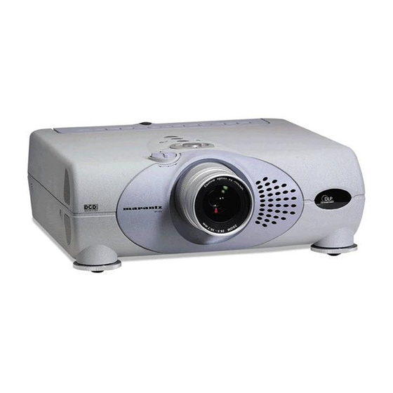
PROJECTOR LAYOUT AND FUNCTIONAL OVERVIEW Front and Top !1 o !0 !6 !5 !4 VP-12S1 q IR sensor (front and rear) o POWER ON indicator Lights up when the power is turned on. Flashes while the w Projection Lens projector goes into standby mode for about one minute. -
Page 7: Right Side And Rear
"INTERNAL". When using this projector in a system with a Connect the optical input from an audio equipment. Marantz DVD player or AV Receiver equipped with a remote Audio out terminal of DV-IN signal. sensor, set the switch to "EXTERNAL". - Page 8 ⁄1 TRIG.2(TRIGGER 2) Select ON or OFF at each aspect mode, such as Full, Normal, Zoom, and Through to control screen aspect ratio with powered up/down dual aspect ratio screen. Note: Do not use TRIG.1 and TRIG.2, as the power source. ⁄2 LIGHT ON/OFF Select ON : The connector panel lights up.
-
Page 9: Bottom
INTRODUCTION Bottom q Adjustment lever w Ventilation holes Notes: Lift the projector and turn the adjustment lever right or left. • Do not place anything near the ventilation holes to avoid The adjustable feet will extend from the projector. Then, overheat inside the unit. -
Page 10: Remote Controller
When the key is pressed, the mode toggles Dynamic1, Dynamic2, Dynamic3 and Dynamic Default. Note : If you need discrete command for above picture modes, you can down load from "www.marantz.com". ¡3 INFO key ¡0 ¡2 Turn the information menu on or off. -
Page 11: Preparing The Remote Controller
INTRODUCTION Preparing the Remote Controller Open the cover. CAUTION – The available battery types are limited: manganese dry cell and alkaline dry cell. – Do not mix different battery types. – Do not mix old and new batteries. – Only batteries of the same type are to be used. –... -
Page 12: Installation
Ceiling Throw distance Note : Lens shift position is at Full up. CAUTION – For ceiling installation, consult with Marantz authorized dealer. – Do not look into the lens when the projector is turned on. It could damage your eyesight. -
Page 13: Distance Between The Projector And The Screen (Throw Distance)
SET UP PROCEDURES Distance between the projector and the screen (throw distance) Screen size (Diagonal) V P - 1 2 S 1 Throw distance 16:9 screen 4:3 screen Screen Size Throw distance Throw distance (Diagonal) Minimum Maximum Minimum Maximum inch inch inch inch... -
Page 14: Image Position Adjustment
Image Position Adjustment You can adjust the image position with the Lens Shift knob. Turn the Lens Shift knob to clockwise : The image goes up. • Maximum range to throw up : Bottom of the image correspond to the center of the Projection Lens. -
Page 15: Advanced Setting
SET UP PROCEDURES Advanced Setting When the projecting image is a trapezoid, correct it in Keystone-V and/or Keystone-H in the Display Menu. Picture Adjust Keystone V Setting Keystone H Display Auto Adjust Config Picture Shift V Trigger 2 Size V Memory Picture Shift H Size H... -
Page 16: The Screen Image In A Wide Screen (16:9)
The Screen Images in a Wide screen (16:9) • Press the ZOOM key, the NORMAL key or the FULL key on the remote controller for the 4:3 aspect ratio video source. • Press the FULL key on the remote controller for 16:9 aspect ratio video source, such as 1080i, 1035i, and 720p video systems. •... -
Page 17: The Screen Image In A 4:3 Screen
SET UP PROCEDURES The Screen Images in a 4:3 screen • Press the ZOOM key, the NORMAL key or the FULL key on the remote controller for the 4:3 aspect ratio video source. • Press the FULL key on the remote controller for 16:9 aspect ratio video source, such as 1080i, 1035i, and 720p video systems. •... -
Page 18: Connection
CONNECTION When making connections be sure to: • Turn off all equipment before making any connections. • Use the proper cables for each connection. • Insert the plug properly. Any plugs that are not fully inserted often generate a noise. When pulling out a cable: •... -
Page 19: Connection With A Dv Camcoder
SET UP PROCEDURES Connection with a DV camcoder DV-SD OUT DV camcoder DIGITAL AUDIO IN Receiver equipment with a Dolby Digital decoder Note: DV IN connector is available for DV-SD format of i.LINK(IEEE1394). Advanced connection RS-232C External Controller Screen 35mm Mini Plug (Mono) Ferrite core REMOTE CONTROL IN REMOTE CONTROL OUT... -
Page 20: Initial Set Up
INITIAL SET UP Connect the supplied AC power cord. The STANDBY indicator lights up and the projector goes into the standby mode. Press the POWER ON key on the remote controller or the POWER key on the projector. The POWER indicator lights up. Press the FOCUS key on the remote controller to display the FOCUS pattern and turn the Focus ring to make an adjustment. -
Page 21: Operations
OPERATIONS OPERATIONS – Color Temp. Menu H: Make white more blue. M: Make white less blue. This setting is approximately Refer to the on-screen menu for making various adjustments 6500 degrees in Kelvin. and settings. L: Make white more reddish. Press the MENU key. -
Page 22: Display
Display Configuration The following adjustments can be made: The following adjustments can be made: 7 OSD Position (16:9 / 4:3 / Through ) ITEM 7 Language (English/ German/ French/ Spanish/ Keystone-V (Electronic vertical Portuguese/ Italian) keystone correction) 7 Ceiling (On/Off) Keystone-H (Electronic horizontal ON: The picture is reversed horizontally and vertically. -
Page 23: Trigger2
OPERATIONS – Reset Lamp Life Memory When replace the lamp unit, before the Lamp Life becomes "0" hours need to reset lamp life. When the user selects “Yes”, the following message appears: Recall the stored memory for preference. The unit has three picture modes: THEATER, STANDARD, and DYNAMIC. -
Page 24: Lamp Life And Replacement Lamp
3 When the lamp life has expired (Lamp Life 0 HOURS), Lamp Life and Replace Lamp the unit will be immediately turned off, and the WARNING indicator will light up in red. Lamp Life Display the remaining lamp life by pressing the INFO key on the remote controller. -
Page 25: Maintenance
Install the new lamp unit. • The lamp may break if handled improperly. • Do not use other than a Marantz replacement lamp unit. Secure the lamp unit with the two screws. Close the lamp cover and secure it with a screw driver. -
Page 26: Troubleshooting
Select the “INTERNAL” position. panel is selected. Notes: • If the lamp still does not function after the replacement and initialization of the lamp life, contact Marantz authorized dealer, or service center. ERROR MODE WARNING/LAMP indicator, POWER ON indicator, and STANDBY indicator diagnose error mode of the projector as follows. -
Page 27: On Screen Message
ADDITIONAL INFORMATION ON SCREEN MESSAGE Use the list below to check the message displayed on the screen. Message Meaning Remedy NO SIGNAL No input signal. Properly connect the cables. REPLACE LAMP! The lamp has reached the end of its life. Replace the lamp and reset lamp life. - Page 28 7 Timing chart V ( Hz ) H ( KHz ) System Resolution Scan NTSC 768x240 59.94 / 60 15.73 PAL-B/G 960x287.5 15.63 SECAM 960x287.5 15.63 480/60p 720x480 59.94 / 60 31.5 576/50p 720x576 31.3 1035/60i 1920x518 59.94 / 60 33.8 1080/60i 1920x540...
-
Page 29: Dimensions
ADDITIONAL INFORMATION DIMENSIONS 7 TOP 182.5 mm 222 mm 404.5 mm 7 FRONT 86 mm : Full up 76 mm : Full down 15 - 61.8 mm [Adjustable] 7 BOTTOM 93.5 mm 110 mm 19.8 mm 182.5 mm 222 mm... - Page 31 PASCO GmbH PO BOX 1280, Sandhausen 69200, Germany NETHERLANDS Marantz Domestic Sales A division of Marantz Europe B.V., Building SFF2, P.O. Box 80002, 5600 JB Eindhoven, The Netherlands NEW ZEALAND Wildash Audio Systems 14 Malvern Road, Mt. Albert, Auckland, New Zealand...