Table of Contents
Advertisement
Form No. 3371-826 Rev A
TITAN ZX4820 or ZX5420
Zero-Turn-Radius Riding Mower
Model No. 74920—Serial No. 312000001 and Up
Model No. 74924—Serial No. 312000001 and Up
To register your product or download an Operator's Manual or Parts Catalog at no charge, go to www.Toro.com.
Original Instructions (EN)
Advertisement
Table of Contents

Related Manuals for Toro 74920


Summary of Contents for Toro 74920
- Page 1 TITAN ZX4820 or ZX5420 Zero-Turn-Radius Riding Mower Model No. 74920—Serial No. 312000001 and Up Model No. 74924—Serial No. 312000001 and Up To register your product or download an Operator's Manual or Parts Catalog at no charge, go to www.Toro.com. Original Instructions (EN)
-
Page 2: Introduction
G010228 and product damage. You are responsible for operating the product properly and safely. You may contact Toro directly at www.Toro.com for product and accessory information, help finding a dealer, or to register your product. Figure 1 Whenever you need service, genuine Toro parts, 1. - Page 3 WARNING Removing standard original equipment parts and accessories may alter the warranty, traction, and safety of the machine. Failure to use original Toro parts could cause serious injury or death. Making unauthorized changes to the engine, fuel or venting system, may violate EPA and CARB regulations.
-
Page 4: Table Of Contents
Rotary Lawnmower Machines......5 Hydraulic System Maintenance ....... 45 Safe Operating Practices ........5 Checking the Hydraulic Oil Level......45 Toro Riding Mower Safety ........6 Changing the Hydraulic System Filter and Model 74920 ............7 Oil..............45 Model 74924 ............7 Mower Deck Maintenance ........ -
Page 5: Safety
Safety ◊ lack of awareness of the effect of ground conditions, especially slopes; ◊ incorrect hitching and load distribution. Safe Operation Practices for Ride-on (riding) Rotary Preparation Lawnmower Machines • While mowing, always wear substantial footwear and long trousers. Do not operate the equipment when This machine meets or exceeds European Standards in barefoot or wearing open sandals. -
Page 6: Toro Riding Mower Safety
• Disengage drive to attachments, stop the engine, The following list contains safety information specific to and disconnect the spark plug wire(s) or remove the Toro products or other safety information that you must ignition key. know that is not included in the CEN standard. -
Page 7: Model 74920
• Do not mow slopes when grass is wet. Slippery Model 74920 conditions reduce traction and could cause sliding and loss of control. Sound Power •... -
Page 8: Sound Pressure
Sound Pressure This unit has a sound pressure level at the operator’s ear of 93 dBA, which includes an Uncertainty Value (K) of 1 dBA. Sound power level was determined according to the procedures outlined in EN 836. Hand-Arm Vibration Measured vibration level for left hand = 3.1 m/s2 Measured vibration level for right hand = 2.7 m/s2 Uncertainty Value (K) = 1.5 m/s2... -
Page 9: Slope Indicator
Slope Indicator G011841 Figure 3 This page may be copied for personal use. 1. The maximum slope you can safely operate the machine on is 15 degrees. Use the slope chart to determine the degree of slope of hills before operating. Do not operate this machine on a slope greater than 15 degrees. Fold along the appropriate line to match the recommended slope. -
Page 10: Safety And Instructional Decals
Safety and Instructional Decals Safety decals and instructions are easily visible to the operator and are located near any area of potential danger. Replace any decal that is damaged or lost. 110-6691 1. Thrown object hazard—keep bystanders a safe distance from the machine. - Page 11 93-7009 1. Warning—do not operate the mower with the deflector up or removed; keep the deflector in place. 2. Cutting/dismemberment hazard of hand or foot, mower blade—stay away from moving parts. Battery Symbols Some or all of these symbols are on your battery 1.
- Page 12 Manufacturer's Mark 1. Indicates the blade is identified as a part from the original machine manufacturer. 114-1606 1. Entanglement hazard, belt—keep all guards in place. 115-9632 5. Fast 1. Power take-off (PTO), Blade control switch on some models 2. Blade control switch—On 6.
- Page 13 120-5466 1. Warning—read the Operator's Manual. 5. Loss of traction/control hazard, slopes—loss of traction/control on a slope, disengage the blade control switch (PTO), proceed off the slope slowly. 2. Warning—read the instructions before servicing or performing 6. Crushing/dismemberment hazard of bystanders, maintenance;...
- Page 14 115-9630 1. Read the Operator's Manual before performing any 4. Check the hydraulic oil every 25 hours maintenance. 2. Check the engine oil every 8 hours 5. Check the caster wheel tire pressure every 25 hours 3. Check the drive wheel tire pressure every 25 hours 6.
- Page 15 119-8986 1. Fuel 2. Full 4. Empty 3. Half...
-
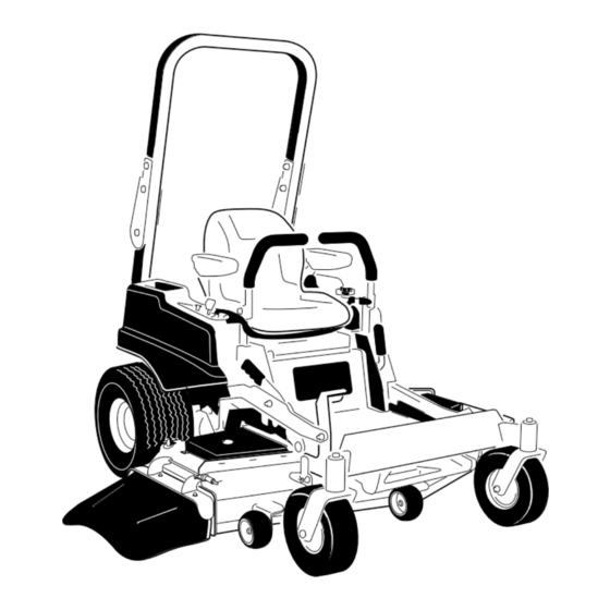
Page 16: Product Overview
Product Overview G015763 Figure 4 1. Drive wheel 4. Motion control levers 7. Front caster wheel 10. Deflector 2. Operator seat 5. Parking brake 8. Anti-scalp roller 3. Roll over protection system 6. Footrest 9. Foot pedal deck lift and (ROPS) height-of-cut G014766... -
Page 17: Controls
Controls switch (PTO) is engaged. Use these times for scheduling regular maintenance (Figure 6). Become familiar with all the controls before you start the engine and operate the machine (Figure 6). Fuel Gauge The fuel window located below the operator position can be used to verify the level of gasoline in the tank (Figure 7). -
Page 18: Operation
Contact your could help you, your family, pets or bystanders avoid Authorized Service Dealer or Distributor or go to injury. www.Toro.com for a list of all approved attachments and accessories. DANGER Mowing on wet grass or steep slopes can cause sliding and loss of control. -
Page 19: Using The Rollover Protection System (Rops)
G015033 Figure 8 1. Safe Zone-use the machine here G015034 2. Use walk behind mower and/or hand trimmer near drop-offs Figure 9 and water. 3. Water Important: Always use the seat belt with the roll bar in the raised position. Using the Rollover Protection 3. -
Page 20: Fuel Gauge
• Do Not use gasoline containing methanol. DANGER • Do Not store fuel either in the fuel tank or fuel In certain conditions, gasoline is extremely containers over the winter unless a fuel stabilizer is flammable and highly explosive. A fire or explosion used. -
Page 21: Checking The Engine Oil Level
G010077 Figure 11 1. Fuel gauge window Filling the Fuel Tank Make sure the engine is shut off and the motion G010475 controls are in the park position. Figure 12 Important: Do Not overfill fuel tank. Fill the fuel tank to the bottom of the filler neck. The empty space in the tank allows the fuel to expand. -
Page 22: Operating The Throttle
Releasing the Parking Brake G010079 Figure 14 Operating the Throttle The throttle control can be moved between Fast and Slow positions (Figure 15). G008959 Figure 16 Always use the fast position when turning on the mower deck with the blade control switch (PTO). 1. -
Page 23: Starting And Stopping The Engine
Starting and Stopping the between attempts. Failure to follow these instructions can burn out the starter motor. Engine Note: Additional starting cycles may be required when starting the engine for the first time after the Starting the Engine fuel system has been without fuel completely. 1. -
Page 24: Operating The Mower Blade Control Switch (Pto)
G008945 Figure 21 Disengaging the Blade Control Switch (PTO) G009174 Figure 22 G017771 The Safety Interlock System Figure 20 WARNING If safety interlock switches are disconnected or Operating the Mower Blade damaged the machine could operate unexpectedly Control Switch (PTO) causing personal injury. -
Page 25: Driving Forward Or Backward
Testing the Safety Interlock System Using the Motion Control Levers Test the safety interlock system before you use the machine each time. If the safety system does not operate as described below, have an Authorized Service Dealer repair the safety system immediately. 1. -
Page 26: Stopping The Machine
blade control switch (PTO), and turn the ignition key to off. Set the parking brake when you leave the machine; refer to Setting the Parking Brake. Remember to remove the key from the ignition switch. CAUTION Children or bystanders may be injured if they move or attempt to operate the tractor while it is unattended. -
Page 27: Adjusting The Anti-Scalp Rollers
Adjusting the Height-of-Cut 2. Remove the pin from the height-of-cut bracket (Figure 27). The height-of-cut can be adjusted from 1-1/2 to 3. Select the lower hole on the lock decal and insert 4-1/2 inch (38 to 114 mm) in 1/4 inch (6 mm) the pin (Figure 27). -
Page 28: Adjusting The Motion Control Levers
While sitting in the operator's position, raise the seat 1. Loosen the upper bolt holding the control lever to adjustment lever slightly and move the seat forward or the control arm shaft. backward to the desired position (Figure 29). 2. Loosen the lower bolt just enough to pivot the control lever fore or aft. -
Page 29: Converting The 48 Inch Mower To Side Discharge
Side discharge performance can be improved by replacing the mulching blades with Figure 32 standard cutting blades obtained from your local authorized Toro dealer. To maintain optimum mulching 1. Locknut (5/16 inch) 3. Left baffle performance, always install the mulching blades that are 2. -
Page 30: Converting The 54 Inch Mower To Side Discharge
Side discharge performance can be improved by replacing the mulching blades with standard cutting blades obtained from your local authorized Toro dealer. To maintain optimum mulching Figure 34 performance, always install the mulching blades that are shipped with this unit when changing back to mulching 1. - Page 31 G010712 locknut on the side wall of the mower deck securing the left baffle to the deck. G011149 Figure 36 1. Locknut (5/16 inch) 3. Left baffle Figure 37 2. Carriage bolt (5/16 x 3/4 4. Install fasteners here inch) 1.
-
Page 32: Using The Side Discharge
Note: Standard cutting blades will improve discharge performance and can obtained from your local authorized Toro dealer. 17. Install the mower as described in the Installing the Mower procedure in the Maintenance section for more information. Using the Side Discharge The mower has a hinged grass deflector that disperses clippings to the side and down toward the turf. -
Page 33: Operating Tips
If enhances decomposition and fertilization. a blade is damaged or worn, replace it immediately with a genuine TORO replacement blade. Mow at Correct Intervals Normally, mow every four days. But remember, grass grows at different rates at different times. -
Page 34: Maintenance
Maintenance Recommended Maintenance Schedule(s) Maintenance Service Maintenance Procedure Interval • Change the engine oil. After the first 8 hours • Change the hydraulic system filter and oil. After the first 50 hours • Check the safety interlock system. • Check the engine oil level. •... - Page 35 Figure 40 Located on the seat pan underside 1. Read the Operator's Manual before performing any 4. Check the hydraulic oil every 25 hours maintenance. 2. Check the engine oil every 8 hours 5. Check the caster wheel tire pressure every 25 hours 3.
-
Page 36: Premaintenance Procedures
Premaintenance Lubrication Procedures Greasing the Bearings Raising the Seat Service Interval: Every 25 hours—Grease all lubrication points. Make sure the motion control levers are locked in the Grease Type: No. 2 General Purpose Lithium Base neutral lock position. Lift the seat forward. Grease The following components can be accessed by raising 1. -
Page 37: Engine Maintenance
Engine Maintenance Cleaning the Element Service Interval: Every 100 hours—Service the paper element (more often in dusty, dirty WARNING conditions). Contact with hot surfaces may cause personal Every 200 hours/Yearly (whichever injury. comes first)—Replace the paper Keep hands, feet, face, clothing and other body element (more often in dusty, dirty parts away the muffler and other hot surfaces. -
Page 38: Changing The Engine Oil
WARNING Contact with hot surfaces may cause personal injury. Keep hands, feet, face, clothing and other body parts away the muffler and other hot surfaces. Important: Do not overfill the crankcase with oil because damage to the engine may result. Do not run engine with oil below the low mark because the engine may be damaged. -
Page 39: Servicing The Spark Plug
Changing the Engine Oil Filter Service Interval: Every 200 hours—Change the oil filter. (more often in dusty, dirty conditions) Note: Change the engine oil filter more frequently when operating conditions are extremely dusty or sandy. 1. Drain the oil from the engine; refer to Changing the Engine Oil. -
Page 40: Cleaning The Cooling System
Installing the Spark Plug check and adjust the air gap. Install a new spark plug(s) if necessary. Tighten the spark plug(s) to 16 ft-lb (22 N-m). Type: NGK BPR4ES (or equivalent) Air Gap: 0.030 inch (0.76 mm) Removing the Spark Plug 1. -
Page 41: Fuel System Maintenance
Fuel System Maintenance Replacing the Fuel Filter Service Interval: Every 100 hours/Yearly (whichever comes first) (more often under dusty, dirty conditions). 1. Disengage the blade control switch (PTO), move the motion control levers to the neutral lock position, and set the parking brake. 2. -
Page 42: Electrical System Maintenance
Electrical System WARNING Maintenance Incorrect battery cable routing could damage the machine and cables causing sparks. Sparks can cause the battery gasses to explode, resulting in Servicing the Battery personal injury. • Always Disconnect the negative (black) battery Service Interval: Monthly cable before disconnecting the positive (red) cable. -
Page 43: Servicing The Fuses
Installing the Battery 1. Position battery in the tray with the terminal posts opposite from the fuel tank (Figure 53). 2. First, install the positive (red) battery cable to positive (+) battery terminal. 3. Then install the negative battery cable to the negative (-) battery terminal. -
Page 44: Drive System Maintenance
Drive System Maintenance Checking the Tire Pressure Service Interval: Every 25 hours—Check tire pressure. Maintain the air pressure in the front and rear tires as specified. Uneven tire pressure can cause uneven cut. Check the pressure at the valve stem (Figure 56). Check the tires when they are cold to get the most accurate pressure reading. -
Page 45: Hydraulic System Maintenance
Hydraulic System 2. Locate the filter and guards on each transaxle drive system (Figure 58). Remove three screws securing Maintenance the filter guard and guard. Oil Type: 20W-50 engine oil. G010254 Important: Use oil specified or equivalent. Other fluids could cause system damage. Checking the Hydraulic Oil Level Service Interval: Every 25 hours... -
Page 46: Bleeding The Hydraulic System
hydraulic filters and oil can result in irreparable damage to the transaxle drive system. Bleeding the Hydraulic System 1. Raise the rear of machine up and support with jack stands (or equivalent support) just high enough to allow drive wheels to turn freely. G010333 Figure 60 1. -
Page 47: Mower Deck Maintenance
If a blade is damaged or worn, Checking for Bent Blades replace it immediately with a genuine Toro replacement Note: The machine must be on a level surface for the blade. For convenient sharpening and replacement, you following procedure. -
Page 48: Removing The Blades
1/8 inch (3mm), the blade spindle could be bent. 5. Measure from the tip of the blade to the flat surface Contact an Authorized Toro Dealer for service. here. The variance should be no more than 1/8 inch B. If the variance is within constraints, move to the (3mm). -
Page 49: Mower Deck Leveling
Figure 68 1. Blade 2. Balancer Installing the Blades 1. Install the blade onto the spindle shaft (Figure 66). Important: The curved part of the blade must be pointing upward toward the inside of the mower to ensure proper cutting. 2. -
Page 50: Leveling The Mower Deck
are not within 3/16 inch (5 mm), an adjustment is required; continue to the Leveling procedure. Figure 70 1. Blades front to rear 3. Measure from the tip of the blade to the flat surface Figure 69 here 1. Blades side to side 3. -
Page 51: Inspecting The Belts
5. Remove the floor pan to access the idler pulley; refer to the Removing the Floor Pan procedure in Premaintenance. 6. Using a spring removal tool, (Toro part no. 92-5771), remove the idler spring from the deck post to remove tension on the idler pulley (Figure 73). -
Page 52: Removing The Mower
11. Ensure that the belt is properly seated in all pulleys. 12. To install the belt covers, insert the tabs on the each cover into the corresponding slots on the deck bracket, ensuring that they seat. Rotate the cover to the deck and slide the notches under the loosened bolts until they are seated. - Page 53 4. Lift the loop end of the spring and place it into the WARNING notch on the deflector bracket (Figure 77). An uncovered discharge opening could allow the lawn mower to throw objects in the operator’s or bystander’s direction and result in serious injury. Also, contact with the blade could occur.
-
Page 54: Cleaning
Cleaning Washing the Underside of the Mower Service Interval: Before each use or daily—Clean the mower housing. Wash the underside of the mower after each use to prevent grass buildup for improved mulch action and clipping dispersal. 1. Park the machine on a level surface and disengage the blade control switch. -
Page 55: Waste Disposal
Storage WARNING A broken or missing washout fitting could Cleaning and Storage expose you and others to thrown objects or blade contact. Contact with blade or thrown debris 1. Disengage the blade control switch (PTO), set the can cause injury or death. parking brake, and turn the ignition key to Off. - Page 56 B. Run the engine to distribute conditioned fuel through the fuel system (5 minutes). C. Stop the engine, allow it to cool, and drain the fuel tank. D. Restart the engine and run it until it stops. E. Dispose of fuel properly. Recycle as per local codes.
-
Page 57: Troubleshooting
Troubleshooting Problem Possible Cause Corrective Action Starter does not crank 1. Blade control switch (PTO) is engaged. 1. Move blade control switch (PTO) to disengaged. 2. Parking brake is not on. 2. Set the parking brake. 3. Drive levers are not in neutral lock 3. - Page 58 Problem Possible Cause Corrective Action Machine does not drive. 1. By pass valves is not closed tight. 1. Tighten the by pass valves. 2. Pump belt is worn, loose or broken. 2. Change the belt. 3. Pump belt is off a pulley. 3.
-
Page 59: Schematics
Schematics G014723 Wire Diagram (Rev. B) - Page 60 Notes:...
- Page 61 Notes:...
- Page 62 The Way Toro Uses Information Toro may use your personal information to process warranty claims, to contact you in the event of a product recall and for any other purpose which we tell you about. Toro may share your information with Toro's affiliates, dealers or other business partners in connection with any of these activities. We will not sell your personal information to any other company.
- Page 63 Spypros Stavrinides Limited Cyprus 357 22 434131 Surge Systems India Limited India 91 1 292299901 T-Markt Logistics Ltd. Hungary 36 26 525 500 Toro Australia Australia 61 3 9580 7355 Toro Europe BVBA Belgium 32 14 562 960 374-0269 Rev C...
- Page 64 Toro's option, under warranty at no cost for parts and labor. Frame failure due to misuse or abuse and failure or repair required due to rust or corrosion are not covered.