Alcatel-Lucent OmniSwitch 6900 Hardware User's Manual
Hide thumbs
Also See for OmniSwitch 6900:
- Hardware user's manual (106 pages) ,
- Troubleshooting manual (148 pages) ,
- User manual (53 pages)

Related Manuals for Alcatel-Lucent OmniSwitch 6900


Summary of Contents for Alcatel-Lucent OmniSwitch 6900
- Page 1 Part No. 060334-10, Rev. A September 2011 OmniSwitch 6900 Hardware Users Guide www.alcatel-lucent.com...
- Page 2 This user guide documents OmniSwitch 6900 hardware, including chassis and associated components. The specifications described in this guide are subject to change without notice. Copyright © 2011 by Alcatel-Lucent. All rights reserved. This document may not be reproduced in whole or in part without the express written permission of Alcatel-Lucent.
-
Page 3: Table Of Contents
OS6900-X20 Rear Panel ..................2-2 OS6900-X40 Front Panel ..................2-3 OS6900-X40 Rear Panel ..................2-3 Chassis Status LEDs ....................2-5 OmniSwitch 6900 Expansion Modules ................2-6 OS-XNI-U4 ......................2-6 OS-XNI-U12 ......................2-6 Plug-In Module Status LEDs ................2-6 Mounting the Switch ....................... 2-7 General Mounting Recommendations .............. - Page 4 Contents Plug-In Modules ......................2-13 Hot-Swapping Plug-In Modules ................2-13 Installing Plug-In Modules ..................2-14 Removing Plug-In Modules ................... 2-16 Power Supplies ......................2-17 AC Power Supply ....................2-17 AC Power Supply LED States ................. 2-18 DC Power Supply ....................2-19 DC Power Supply LED States .................
- Page 5 Contents DC Power Supply Connection Warning ................ A-9 Read Important Safety Information Warning ..........A-10 Restricted Access Location Warning ............. A-10 Wrist Strap Warning ..................A-10 Instrucciones de seguridad en español ................. A-11 Advertencia sobre el levantamiento del chasis ..........A-11 Advertencia de las tapaderas en blanco ............
- Page 6 Contents OmniSwitch 10K Hardware Users Guide September 2011...
-
Page 7: About This Guide
About This Guide This OmniSwitch 6900 Hardware Users Guide describes OmniSwitch 6900 switch components and basic switch hardware procedures. Supported Platforms The information in this guide applies only to OmniSwitch 6900 switches. Who Should Read this Manual? The audience for this users guide is network administrators and IT support personnel who need to configure, maintain, and monitor switches and routers in a live network. -
Page 8: What Is In This Manual
Each chapter in this guide focuses on a specific hardware component or a set of hardware components. All descriptive, technical specification, and procedural information for a hardware component can be found in the chapter dedicated to that component. page -viii OmniSwitch 6900 Hardware Users Guide September 2011... -
Page 9: Documentation Roadmap
Pertinent Documentation: OmniSwitch 6900 Getting Started Guide Release Notes A hard-copy OmniSwitch 6900 Getting Started Guide is included with your switch; this guide provides all the information you need to get your switch up and running the first time. It provides information on unpacking the switch, rack mounting the switch, installing NI modules, unlocking access control, setting the switch’s IP address, and setting up a password. - Page 10 CLI-to-MIB variable mapping information for all CLI commands supported by the switch. This guide can be consulted anytime during the configuration process to find detailed and specific information on each CLI command. page -x OmniSwitch 6900 Hardware Users Guide September 2011...
-
Page 11: Related Documentation
Related Documentation The following are the titles and descriptions of all the OmniSwitch 6900 user manuals: • OmniSwitch 6900 Getting Started Guide Describes the hardware and software procedures for getting an OmniSwitch up and running. Also provides information on fundamental aspects of OmniSwitch software architecture. -
Page 12: Technical Support
With 24-hour access to Alcatel-Lucent’s Service and Support web page, you’ll be able to view and update any case (open or closed) that you have reported to Alcatel-Lucent’s technical support, open a new case or access helpful release notes, technical bulletins, and manuals. -
Page 13: Chapter 1 Omniswitch 6900
1 OmniSwitch 6900 The OmniSwitch 6900 (OS6900) is a family of standalone aggregation switches that can also be installed as top-of-rack boxes in data centers. The OS6900 supports either 20 or 40 non-combo SFP+ ports, as well as two expansion modules. Refer to the information below for model number and component type. -
Page 14: Omniswitch 6900 Availability Features
Chapter 2, “Chassis and Power Supplies” for detailed information on hot-swapping plug-in modules. For information on adding and removing power supplies and plug-in modules, refer to Chapter 2, “Chassis and Power Supplies.” page 1-2 OmniSwitch 6900 Hardware Users Guide September 2011... -
Page 15: Hardware Monitoring
The user enters “show” commands that output information to the console. The Show commands for all the features are described in detail in the OmniSwitch CLI Reference Guide. OmniSwitch 6900 Hardware Users Guide September 2011 page 1-3... - Page 16 OmniSwitch 6900 Availability Features OmniSwitch 6900 page 1-4 OmniSwitch 6900 Hardware Users Guide September 2011...
-
Page 17: Chapter 2 Chassis And Power Supplies
2 Chassis and Power Supplies This chapter includes detailed information on the OmniSwitch 6900 chassis, as well as fan tray and power supply components. Topics include: • Technical specifications, page 2-4. • Switch mounting information, page 2-7. • Power supplies and power supply redundancy, page 2-16. -
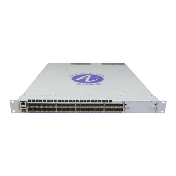
Page 18: Omniswitch 6900 Chassis
USB Port Console Port Status LEDs 20 Non-Combo 10G Ethernet Ports Expansion Module Slot OS6900-X20 Rear Panel Item Description Chassis Grounding Lug Fan Tray Power Supply Bays (OS6900-BP-F AC power supplies shown) page 2-2 OmniSwitch 6900 Hardware Users Guide September 2011... -
Page 19: Os6900-X40 Front Panel
USB Port Console Port Status LEDs 40 Non-Combo 10G Ethernet Ports Expansion Module Slot OS6900-X40 Rear Panel SLOT Item Description Chassis Grounding Lug Expansion Module Slot Fan Tray Power Supply Bays OmniSwitch 6900 Hardware Users Guide September 2011 page 2-3... - Page 20 *Note On Chassis Versus Ambient Temperatures. Chassis temperature refers to the sensor reading of the internal switch temperature (threshold or danger). Ambient temperature refers to the temperature of the room (which will always be less than the chassis temperature). page 2-4 OmniSwitch 6900 Hardware Users Guide September 2011...
-
Page 21: Chassis Status Leds
Solid Green EMP port link is up Blinking Green EMP port link is active Solid Green Power save features are active Port LEDs Solid Green Valid link Blinking Green Port is active OmniSwitch 6900 Hardware Users Guide September 2011 page 2-5... -
Page 22: Omniswitch 6900 Expansion Modules
OS-XNI-U12 CLASS 1 LASER PRODUCT Item Description Lock Lever and Captive Screws SFP+ Ports Status LEDs Plug-In Module Status LEDs State Description Port LEDs Solid Green Valid Link Blinking Green Traffic/Activity page 2-6 OmniSwitch 6900 Hardware Users Guide September 2011... -
Page 23: Mounting The Switch
Appropriate consideration of equipment nameplate ratings should be used when addressing this concern. Reliable Earthing. Reliable earthing of rack-mounted equipment should be maintained. Particular attention should be given to supply connections other than direct connections to the branch (e.g., use of power strips). OmniSwitch 6900 Hardware Users Guide September 2011 page 2-7... -
Page 24: Airflow Recommendations
Note. Clearance is not required at the top and bottom of the chassis. The OmniSwitch 6900 fan tray is located at the rear of the switch and draws air through the intake vents located at the top-front of the chassis. The air is directed straight through the chassis’ module compart- ment and past the switch’s circuit boards. -
Page 25: Blank Cover Panels
Note. Because they regulate airflow and help protect internal chassis components, blank cover panels should be installed over empty module slots and power supply bays at all times. Blank Panels and Chassis Airflow OmniSwitch 6900 Hardware Users Guide September 2011 page 2-9... -
Page 26: Rack-Mounting
• The chassis has rack-mount flanges that support standard 19-inch rack mount installations. • Alcatel-Lucent does not provide rack-mount screws. Use the screws supplied by the rack vendor. • To prevent a rack from becoming top heavy, it is recommended that you install the switch at the bottom of the rack whenever possible. - Page 27 8 Once the flanges are aligned, install the remaining screws in all four flanges. Be sure that all screws are securely tightened. OmniSwitch 6900 Hardware Users Guide September 2011 page 2-11...
-
Page 28: Standalone (Non-Rack Mounted) Installations
AC outlets. For recommended airflow allowances, refer to page 2-8. Note. Chassis must be placed “right side up.” Never attempt to operate a switch while it is placed on its top or side. page 2-12 OmniSwitch 6900 Hardware Users Guide September 2011... -
Page 29: Plug-In Modules
5 Wait for a ChassisSupervisor niMgr notification similar to the following to display on the console: +++ Expansion module 2 ready! 6 Re-insert all transceivers into new module. 7 Re-connect all cables to transceivers. OmniSwitch 6900 Hardware Users Guide September 2011 page 2-13... -
Page 30: Installing Plug-In Modules
2 When the bottom portion of the lever meets the chassis, be sure that the catches grab the chassis sheet metal, then push the lever up and back as shown. This will fully seat the module in the chassis backplane. page 2-14 OmniSwitch 6900 Hardware Users Guide September 2011... - Page 31 Chassis and Power Supplies Plug-In Modules 3 Tighten the captive screw to complete the installation. OmniSwitch 6900 Hardware Users Guide September 2011 page 2-15...
-
Page 32: Removing Plug-In Modules
2 Pull down on the lock lever to release the plug-in module from the chassis backplane. 3 Using the lock lever as a handle, pull the plug-in module straight back and out of the chassis. page 2-16 OmniSwitch 6900 Hardware Users Guide September 2011... -
Page 33: Power Supplies
Chassis and Power Supplies Power Supplies Power Supplies OmniSwitch 6900 power supplies are located at the rear of the switch chassis. Refer to page 2-2 page 2-3 for more information on component location. Two slots are provided. If a second power supply is installed, it will assume a standby role. -
Page 34: Ac Power Supply Led States
No AC power is being provided to this power supply Flashing Green/Red Power supply warning Solid Red Power supply failure No AC power is being provided to any power supply installed in the chassis; all power supplies are effectively off page 2-18 OmniSwitch 6900 Hardware Users Guide September 2011... -
Page 35: Dc Power Supply
No DC power is being provided to this power supply Flashing Blue/Red Power supply warning Solid Red Power supply failure No DC power is being provided to any power supply installed in the chassis; all power supplies are effectively off OmniSwitch 6900 Hardware Users Guide September 2011 page 2-19... -
Page 36: Dc Power Supply Connections
Observe proper polarity when connecting to a fuse panel. The cable wire leads must be connected as follows: • Green/yellow - ground • Black - return • Red - -48VDC Note. The battery return conductor is an Isolated DC Return (DC-1). page 2-20 OmniSwitch 6900 Hardware Users Guide September 2011... -
Page 37: Installing Power Supplies
3 Plug the power cord (provided) into the power supply’s socket. Note. The chassis does not provide an on/off switch. Connecting a the power supplies to a power source will boot the switch. OmniSwitch 6900 Hardware Users Guide September 2011 page 2-21... -
Page 38: Removing Power Supplies
Lock Tab Note. If you are not replacing the power supply, be sure to install a blank cover panel over the empty power supply bay. page 2-22 OmniSwitch 6900 Hardware Users Guide September 2011... -
Page 39: Chassis Fan Tray
Chassis Fan Tray Chassis Fan Tray The OmniSwitch 6900 chassis houses a single fan tray with four independently-operating fan. The fans are the main temperature control components for the switch, providing cooling airflow for all chassis components. This airflow is a crucial factor in the switch’s overall operability. Refer to “Airflow... -
Page 40: Removing The Fan Tray
Removing the Fan Tray 1 Begin by loosening the two captive screws located at the left and right sides of the tray’s front panel. 2 Pull the fan tray straight out of the chassis. page 2-24 OmniSwitch 6900 Hardware Users Guide September 2011... -
Page 41: Installing The Fan Tray
1 Insert the tray into the chassis slot and slide it straight back until it meets the chassis backplane connectors. 2 When the fan tray is firmly seated in the chassis, tighten the two captive screws at the left and right sides of the fan tray’s front panel. OmniSwitch 6900 Hardware Users Guide September 2011 page 2-25... -
Page 42: Grounding The Chassis
Use this connector to supplement the ground provided by the AC power cord. To do so, install a Panduit Grounding Lug (type LCD8-10A-L) using 8AWG copper conductors to the paint-free area. Refer to the rear chassis views on page 2-2 for location details. page 2-26 OmniSwitch 6900 Hardware Users Guide September 2011... -
Page 43: Monitoring Chassis Components
To check the switch’s current temperature status, use the show temperature command. For example: -> show temperature For more information about this command, see the “Chassis Management and Monitoring Commands” chapter in the OmniSwitch CLI Reference Guide. OmniSwitch 6900 Hardware Users Guide September 2011 page 2-27... -
Page 44: Temperature Errors
To check the switch’s current fan tray status, use the command. For example: show fan -> show fan For more information about this command, see the “Chassis Management and Monitoring Commands” chapter in the OmniSwitch CLI Reference Guide. page 2-28 OmniSwitch 6900 Hardware Users Guide September 2011... -
Page 45: Appendix A Regulatory Compliance And Safety Information
A Regulatory Compliance and Safety Information This appendix provides information on regulatory agency compliance and safety for OmniSwitch 6900 switches. Declaration of Conformity: CE Mark This equipment is in compliance with the essential requirements and other provisions of Directive 2004/108/EC (EMC), 2006/95/EC (LVD), 91/263/EEC (Telecom Terminal Equipment, if applicable), 1999/5/EC (R&TTE, if applicable) as amended by Directive 93/68/EEC... -
Page 46: China Rohs: Hazardous Substance Table
对销售之日的所售产品, 本表显示, 阿尔卡特朗讯公司供应链的电子信息产品可能包含这些物质。注意: 在所售产 品中可能会也可能不会含有所有所列的部件。 This table shows where these substances may be found in the supply chain of Alcatel-Lucent electronic information products, as of the date of sale of the enclosed product. Note that some of the component types listed above may or may not be a part of the enclosed product. - Page 47 Regulatory Compliance and Safety Information China RoHS: Hazardous Substance Table Products are packaged using one or more of the following packaging materials: Corrugated Cardboard Corrugated Fiberboard Low-Density Polyethylene OmniSwitch 6900 Hardware Users Guide September 2011 page A-3...
-
Page 48: Standards Compliance
The product bears the CE mark. In addition it is in compliance with the following other safety and EMC standards: All hardware switching modules used in an OmniSwitch 6900 switch comply with Class A standards. Modules with copper connectors meet Class A requirements using unshielded (UTP) cables. -
Page 49: Canada Class A Statement
RÈglement sur le brouillage radioèlectrique ètabli par le ministère des Communications du Canada. JATE This equipment meets the requirements of the Japan Approvals Institute of Telecommunications Equipment (JATE). OmniSwitch 6900 Hardware Users Guide September 2011 page A-5... -
Page 50: Cispr22 Class A Warning
This is a Class A Information Product. When used in a residential environment, it may cause radio frequency interference. Under such circumstances, the user may be requested to take appropriate countermeasure. page A-6 OmniSwitch 6900 Hardware Users Guide September 2011... -
Page 51: Translated Safety Warnings
Deutsch: Dieses Gerät soll nur von Personal installiert oder gewartet werden, welches in elektrischen und mechanischen Grundlagen ausgebildet ist. Español: Estos equipos deben ser instalados y atendidos exclusivamente por personal adecuadamente formado y capacitado en técnicas eléctricas y mecánicas. OmniSwitch 6900 Hardware Users Guide September 2011 page A-7... -
Page 52: Invisible Laser Radiation Warning
Netzverbindungen getrennt sind bevor das Gerät gewartet oder bewegt wird. Español: Antes de empezar a trabajar con un sistema, asegurese que el interruptor está cerrado y el cable eléctrico desconectado. page A-8 OmniSwitch 6900 Hardware Users Guide September 2011... -
Page 53: Proper Earthing Requirement Warning
Erde angeschlossen werden. Español: Para EMC/EMI, cada fuente de alimentación de CC/CC requiere que el cable de tierra esté conectado desde cada fuente de alimentación de CC/CC a la conexión a tierra común. OmniSwitch 6900 Hardware Users Guide September 2011 page A-9... -
Page 54: Read Important Safety Information Warning
Español: Debido a las descargas electrostáticas (ESD) puede dañar los componentes del interruptor, debe seguir los procedimientos adecuados para eliminar la EDS de su persona y sus alrededores antes de manipular los componentes del interruptor. page A-10 OmniSwitch 6900 Hardware Users Guide September 2011... -
Page 55: Instrucciones De Seguridad En Español
Deseche las baterías usadas según las instrucciones del fabricante. Las instrucciones del fabricante son como sigue: Devuelva el módulo con la batería del litio a Alcatel-Lucent. La batería del litio será substituida en la fábrica de Alcatel-Lucent. -
Page 56: Advertencia Sobre Una Apropiada Conexión A Tierra
Para este propósito, Alcatel-Lucent proporciona una pulsera antiestática y un terminal que pone a tierra situados cerca de la parte superior derecha del chasis. Para que la pulsera antiestática sea eficaz en la eliminación de ESD, las fuentes de alimentación se deben instalar en el chasis y enchufar en las salidas de CA con descarga a...