Table of Contents
Advertisement
Quick Links
Advertisement
Table of Contents

Related Manuals for E-FLITE MINI EDGE 540 3D


Summary of Contents for E-FLITE MINI EDGE 540 3D
- Page 1 Mini Edge 540 3D Assembly Manual...
-
Page 2: Table Of Contents
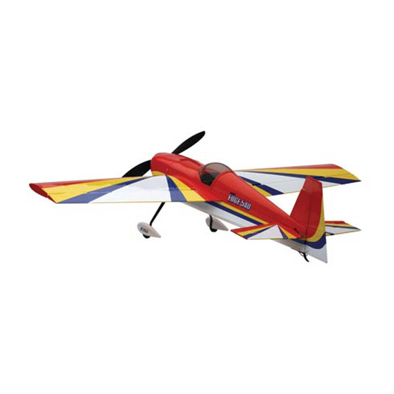
Introduction Table of Contents Introduction ..............2 Thank you for purchasing the Mini Edge 540 3D ARF, Specifications .............2 which is based on the popular 33% Hangar 9® Edge 540 Contents of Kit/Parts Layout .........3 and is capable of the same extreme 3D performance you Required Electronics &... -
Page 3: Contents Of Kit/Parts Layout
EFL2232 Canopy EFLA202 Micro Tail Skid EFL2233 Painted Cowl EFLA203 Micro Control Connectors EFL2234 Painted Wheel Pants EFLA213 E-flite/JR/Horizon Decals EFLA214 Micro Pull-Pull Set EFLA216 Spinner EFLA221 Foam Park Wheels, 1.5" EFLM207 Pinion Gear, 10T 0.4 Module EFLM221 Gearbox, 6.6:1... -
Page 4: Required Electronics & Accessories
Required Electronics & Accessories Recommended High Performance Motor Setup* JRP6654** 6102FM, R610UL & 4-S241—Complete Radio System EFLM1105 Park 400 Brushless Motor, 3700Kv JRPR610UL** R610UL 6CH FM Receiver, Shrinkwrap EFLM1912 Heat Sink, 20mm x 20mm: Park 400 JRPS241 S241 Sub-Micro Servo (4) EFLP1260 12 x 6 Slow Flyer Prop JRPA212... -
Page 5: Extreme High Performance Motor Setup
Optional Accessories Extreme High Performance Motor Setup* EFLA110 Power Meter EFLA212 Gear Puller: 1–5mm Shaft EFLM1100 Park 400 Brushless Motor, 4200Kv JRPS281 DS281 Micro Digital Servo (4) EFLM1912 Heat Sink, 20mm x 20mm: Park 400 EFLP1260 12 x 6 Slow Flyer Prop Additional Tools and Adhesives (keep extras on hand) EFLB1035... -
Page 6: Important Information About Motor Selection
Important Information About Motor Warning Selection An RC aircraft is not a toy! If misused, it can cause serious bodily harm and damage to property. Fly only in open We are recommending either the E-flite™ Park 400 areas, preferably at AMA (Academy of Model Aeronautics) Brushless Motor with 4200Kv (EFLM1100) or the version approved flying sites, following all instructions included with with 3700Kv (EFLM1105). -
Page 7: Warranty Information
Warranty Information Please note that once assembly of the model has been started, you must contact Horizon Hobby, Inc. directly regarding any warranty question. Please do not contact Horizon Hobby, Inc. guarantees this kit to be free from your local hobby shop regarding warranty issues, even if defects in both material and workmanship at the date of that is where you purchased it. -
Page 8: Landing Gear Installation
Landing Gear Installation 1. Slide the 2mm x 25mm screw through one of the wheels. Thread a 2mm nut onto the screw. Slide a Required Parts 2mm washer onto the screw. This will all fit inside the Fuselage Carbon main gear wheel pant. - Page 9 2. Fit the assembly from Step 1 into the wheel pant. 4. Drill 1/8" (3mm) holes in the tail for the tail skid. Use a 2mm washer and nut to attach the wheel to the lower hole on the landing gear. Note: Use threadlock on both nuts to prevent them from loosening during flight.
- Page 10 5. Glue the tail skid into position using Medium CA. 6. Attach the landing gear using a 3/32" hex wrench, two 4-40 x 1/2" socket head screws and two #4 washers (black).
- Page 11 8. Secure the location of the wheel pants using 2mm x 7. Place the fuselage on its wheels and position the 6mm wood screws and a small Phillips screwdriver. wheel pants parallel to the work surface. Drill a hole through the landing gear into each wheel pant using a hobby knife.
-
Page 12: Aileron Hinging
Aileron Hinging 2. Slide four hinges into the slits in the aileron. Center the slot in the hinge with the hole drilled in Step 1. Required Parts Place a T-pin in each hinge to prevent it from being Wing (left and right) Aileron (left and right) pushed into the wing when installing the aileron. - Page 13 3. Slide the aileron into position. Check to make 4. Firmly grasp the wing and aileron and gently pull sure it can move without interference at the wing on the aileron to ensure the hinges are secure and root.
-
Page 14: Aileron Servos And Linkages
Aileron Servos and Linkages 5. Work the aileron up and down several times to work in the hinges and check for proper movement. Required Parts Wing panel (right and left) Micro control connector (2) 2mm x 4mm screw (2) "... - Page 15 1. Install the grommets and brass eyelets on the servo 2. Place the servo in the wing. Guide the servo lead using instructions provided with the radio system. out through the opening at the wing root. Attach a 6"...
- Page 16 4. Use a hobby knife to enlarge the center hole in 5. Use 6-minute epoxy to attach the control horn the control horn to fit the 3 " (85 mm) long aileron to the aileron. pushrod wire.
- Page 17 6. Attach the micro control connector to the servo 7. Turn on the radio system and center the aileron arms. Be sure to use the included retainer to secure the trim and stick. Make sure the aileron servo is operating micro control connector to the servo arm.
-
Page 18: Wing Installation
Wing Installation 3. Slide the remaining wing panel into position. Secure the panels using 4-40 x 1/2" socket head screws with Required Parts #4 washers (silver) using a 3/32" hex wrench. Fuselage Wing (right and left) Wing tube #4 washer (silver) (2) 4-40 x 1/2"... -
Page 19: Stabilizer And Elevator
Stabilizer and Elevator 2. Measure from the stab tip to the wing tip. Adjust the stab until the measurements are equal. Required Parts Fuselage w/wing installed Stabilizer Elevator CA hinge (4) Filler plug Required Tools and Adhesives Hobby knife Felt-tipped pen Ruler T-pins... - Page 20 4. Double-check the adjustments from Steps 1 through 3. 3. View the airframe from the rear and make sure the Use a felt-tipped pen to trace the outline of the fuselage wing and stab are parallel. If not, lightly sand the stab onto the top and bottom of the stabilizer.
- Page 21 5. Use a sharp hobby knife to cut the covering slightly 6. Hinge the elevator and stabilizer, using the same inside the lines drawn. Be very careful not to cut into process as described in Aileron Hinging. Use 4 the underlying wood, as this will weaken the stab and hinges for this process.
-
Page 22: Rudder And Fin
Rudder and Fin 7. Slide the stab and elevator back into position. Again, check the alignment and make sure everything lines Required Parts up. Wick Thin CA into the joint between the fuselage Fuselage Rudder and stabilizer. Make sure to glue both top and bottom. CA hinge (3) Do not use accelerator—allow the CA to wick in as far Required Tools and Adhesives... - Page 23 2. Remove the covering from the bottom of the fin using 3. Position the fin back onto the fuselage. Use a the same technique used for the stabilizer. square to check the alignment between the fin and stabilizer. Lightly sand the bottom of the fin until the alignment is correct.
- Page 24 4. Use thin CA to glue the fin to the fuselage. 5. Attach the rudder using three CA hinges. Use the technique as described in Aileron Hinging for this procedure. Use thin Ca to glue the filler plug at the rear of the fuselage.
-
Page 25: Motor Installation
Motor Installation Note: When installing your motor into the E-flite™ gearbox, it is very important that your Required Parts gear mesh is set correctly and the gear’s mesh is smooth with no binding. The E-flite Fuselage 6.6:1 gearbox gearbox features adjustable slotted mounting... - Page 26 2. Attach the motor to the gearbox using screws provided 3. Locate the motor support stick. Position the stick so it with the motor. Follow the instructions provided with extends 2 " forward of the firewall as shown. Use the gearbox for some helpful installation hints.
- Page 27 4. Slide the gearbox into position on the motor support stick. Use a hobby knife to make a hole in the gearbox and into the motor stick. Secure the gearbox to the motor stick using a 2mm x 8mm sheet metal screw.
-
Page 28: Rudder And Elevator Servos
Rudder and Elevator Servos 1. Install the grommets and brass eyelets in the elevator servo. Secure a 12" (305 mm) servo extension to the Required Parts servo. Mount the elevator servo using the hardware Fuselage Plastic rudder horn provided with the servo. 2mm x 4mm screw (3) Pull-pull cable 3"... - Page 29 3. Attach the micro control horn to the elevator using the 4. Install the micro control connector onto the elevator control horn backplate and 6-minute epoxy. servo arm. Pass the elevator pushrod wire through the connector. With the radio on and elevator trim centered, center the elevator.
- Page 30 Note: An optional rudder servo location has 5. Lightly sand both sides of the middle section of the been provided at the rear of the fuselage if plastic rudder control horn before installing so the using heavier motors and you choose not to use CA wicks better.
- Page 31 7. Install two micro control connectors into a long 9. Use tape to hold the rudder in neutral. Slide a cable servo arm. Secure them using the control connector crimp onto the control cable. The cable then goes back plates.
- Page 32 10. Use a hobby knife to remove the covering from the 11. Slide the micro cable adjust connector into the micro openings where the cable will enter the fuselage. You control connector and use a 2mm x 3mm screw to can see the exit holes through the covering by holding hold it in position.
- Page 33 12. The cables will cross inside the fuselage to get the 13. Remove the tape from the control surface. Install the proper geometry for the rudder to operate correctly. second cable following Steps 9 through 11. Tension the cables lightly using the cable connectors to pull the surface into neutral.
-
Page 34: Receiver, Battery And Esc Install
BEC capacity. Brushless speed control Required Tools and Adhesives We now have a new version of the E-flite 20A Brushless ESC (EFLA311B) which is equipped with a higher rated, Thin CA heavy-duty BEC that can dissipate more heat and handle Optional Parts higher wattage when using a 3-cell Li-Po battery. - Page 35 Hint: Position the receiver so the ailerons can 1. Check to make sure all servo wires and ESC wires be plugged in easily. can reach the location of the receiver before mounting the receiver. Cut a piece of the hook and loop tape to the size of the receiver.
-
Page 36: Canopy Install
Canopy Install 3. Install the battery in the fuselage using the remaining piece of hook and loop material. The battery must Required Parts be mounted at the forwardmost position against the Fuselage Canopy firewall for proper Center of Gravity. Installing the Required Tools and Adhesives battery into that position may be tight. - Page 37 2. Position the canopy. Trace the outline of the canopy 3. Lightly sand the inside edge of the canopy where it onto the canopy hatch using a felt-tipped pen. contacts the hatch. Also sand the hatch inside the line drawn in the last step.
-
Page 38: Cowling Install
Cowling Install 4. Glue the canopy to the hatch using canopy glue. Tape the canopy into position until the glue cures. Required Parts Fuselage Cowling 12x6 propeller Spinner 3mm locknut 3mm washer 2mm x 8mm wood screw (4) Required Tools and Adhesives Hobby knife Phillips screwdriver (small) ... - Page 39 2. Attach the propeller and spinner using the supplied 3. Check to make sure the propeller and spinner will 3mm washer and 3mm locknut. Make sure not to over- not interfere with the front of the cowl and there is tighten the 3mm locknut.
-
Page 40: Control Throws
Control Throws Ailerons: Low rate 3/4" (19mm) Up/Down High Rate 2" (51mm) Up/Down 1. Turn on the transmitter and receiver of your Mini Elevator: Edge. Check the movement of the rudder using the Low Rate 1/2" (13mm) Up/Down transmitter. When the stick is moved right, the rudder High Rate "... -
Page 41: Center Of Gravity
Center of Gravity Range Test Your Radio An important part of preparing the aircraft for flight is 1. Before each flying session, be sure to range check properly balancing the model. your radio. This is accomplished by turning on your Caution: Do not inadvertently skip this step! transmitter with the antenna collapsed. -
Page 42: 2005 Official Ama
2005 Official AMA 5) I will not fly my model unless it is identified with my name and address or AMA number on or in the National Model Aircraft Safety Code model. (This does not apply to models while being GENERAL flown indoors.) 1) I will not fly my model aircraft in sanctioned events,... - Page 43 3) At all flying sites a straight or curved line(s) must 6) For Combat, distance between combat engagement be established in front of which all flying takes place line and spectator line will be 500 feet per cubic inch with the other side for spectators. Only personnel of engine displacement.
- Page 44 © 2005 Horizon Hobby, Inc. 4105 Fieldstone Road Champaign, Illinois 61822 (877) 504-0233 horizonhobby.com e-fliterc.com 7711...