
Related Manuals for E-FLITE Pawnee Brave Night Flyer EFL6950


Summary of Contents for E-FLITE Pawnee Brave Night Flyer EFL6950
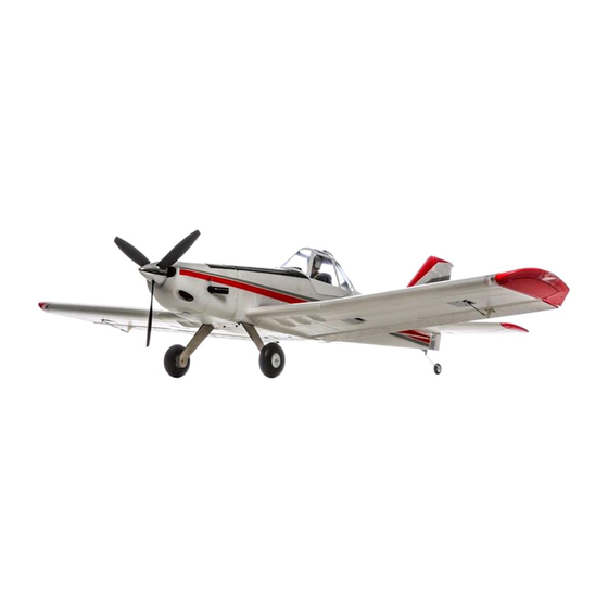
- Page 1 Pawnee Brave Night Flyer Instruction Manual Bedienungsanleitung Manuel d’utilisation Manuale di Istruzioni...
-
Page 2: Safety Precautions And Warnings
NOTICE All instructions, warranties and other collateral documents are subject to change at the sole discretion of Horizon Hobby, LLC. For up-to-date product literature, visit www.horizonhobby.com and click on the support tab for this product. Meaning of Special Language: The following terms are used throughout the product literature to indicate various levels of potential harm when operating this product: NOTICE: Procedures, which if not properly followed, create a possibility of physical property damage AND little or no possibility of injury. -
Page 3: Table Of Contents
Box Contents Quick Start Information Transmitter Set up your transmitter using the Setup transmitter setup chart Hi Rate Low Rate =15mm =10mm =10mm =08mm =15mm =12mm Dual Rates =10mm =9mm =18mm =10mm =18mm =10mm Full Half Flaps =30mm =15mm Center of 89mm back from leading edge at the root. -
Page 4: Prefl Ight
Prefl ight Remove and inspect contents. 10 Test the fl ap operation. Read this instruction manual thoroughly. 11 Perform the Control Direction Test with the transmitter. Charge the fl ight battery. 12 Perform the AS3X Control Direction Test with the aircraft. Setup Transmitter using transmitter setup chart. -
Page 5: Model Assembly
Model Assembly Main Gear Installation Secure the main gear assembly to the fuselage using 4 screws (A). Tail Installation 1. Connect the light connector (Servo style) from the horizontal stab to the fuselage. 2. Install the horizontal stab to the fuselage with the control horn facing down. 3. -
Page 6: Wing Installation
Model Assembly Continued Wing assembly 1. Slide the left and right wing halves together, as shown (fi gure A). 2. Ensure the internal wing lights connectors (JST type connector), aileron servo connectors and navigation light connectors are aligned with the hole (B) created by the two connected wing halves. - Page 7 Model Assembly Continued Wing Installation 2. Guide the aileron servo connectors, wing light and navigation light connec- tors (A) from the wing through the hole in the bottom side of the fuselage. IMPORTANT: The ailerons must be connected to the receiver’s AILE (#2 chan- nel) with a Y-harness (included) for the AS3X system to function properly.
-
Page 8: Clevis Installation
Model Assembly Continued Clevis Installation • Pull the tube from the clevis to the linkage. • Carefully spread the clevis, then insert the clevis pin into the desired hole in the control horn. • Move the tube to hold the clevis on the control horn. Control Surface Centering After assembly and transmitter setup, confi... - Page 9 Model Assembly Continued Optional Flap Installation Before you begin you will need to purchase (2) (SPMA330) servos and a 6 inch Y-harness (SPMA3058) to complete the fl ap installation process. 1. Remove the main wing from the fuselage. 2. Install the servo arm included with the servos, angled rearward as shown (fi...
-
Page 10: Control Horn And Servo Arm Settings
Control Horn and Servo Arm Settings The table to the right shows the factory settings for the control horns and servo Horns Arms arms. Fly the aircraft at factory settings before making changes. NOTICE: If control throws are changed from the factory settings, the AR636 gain values may need to be adjusted. -
Page 11: Battery Installation And Esc Arming
Battery Installation and ESC Arming Battery Selection We recommend the E-fl ite ® 2200mAh 11.1V 3S 30C Li-Po battery (EFLB22003S30). Refer to the Optional Parts List for other recommended batteries. If using a battery other than those listed, the battery should be within the range of capacity, dimensions and weight of the E-fl... -
Page 12: Center Of Gravity (Cg)
Center of Gravity (CG) The CG location is measured from the leading edge of the wing at the root. This CG location has been determined with the recommended Li-Po battery (EFLB22003S30) installed all the way forward in the battery compartment. The easiest way to achieve CG is to balance the aircraft inverted. -
Page 13: In Flight Trimming
In Flight Trimming During your fi rst fl ight, trim the aircraft for level fl ight at 3/4 throttle. Make small trim adjustments with your transmitter’s trim switches to straighten the 3 Seconds aircraft’s fl ight path. After adjusting trim do not touch the control sticks for 3 seconds. This al- lows the receiver to learn the correct settings to optimize AS3X performance. -
Page 14: Post Flight
Post Flight Disconnect the fl ight battery from the ESC (Required for Safety Repair or replace all damaged parts. and battery life). Store the fl ight battery apart from the aircraft and monitor the Power OFF the transmitter. battery charge. Remove the fl... -
Page 15: Troubleshooting Guide
Troubleshooting Guide Problem Possible Cause Solution Throttle not at idle and/or throttle trim too high Reset controls with throttle stick and throttle trim at lowest setting Aircraft will not re- Throttle servo travel is lower than 100% Make sure throttle servo travel is 100% or greater spond to throttle but responds to other Throttle channel is reversed... -
Page 16: Ama National Model Aircraft Safety Code
AMA National Model Aircraft Safety Code Effective January 1, 2014 A. GENERAL B. RADIO CONTROL A model aircraft is a non-human-carrying aircraft capable of sustained fl ight 1. All pilots shall avoid fl ying directly over unprotected people, vessels, in the atmosphere. It may not exceed limitations of this code and is intended vehicles or structures and shall avoid endangerment of life and property exclusively for sport, recreation, education and/or competition. -
Page 17: Limited Warranty
Limited Warranty What this Warranty Covers protection. Ship via a carrier that provides tracking and insurance for lost or Horizon Hobby, LLC, (Horizon) warrants to the original purchaser that the damaged parcels, as Horizon is not responsible for merchandise until it arrives product purchased (the “Product”) will be free from defects in materials and and is accepted at our facility. -
Page 18: Contact Information
Contact Information Country of Purchase Horizon Hobby Phone Number/Email Address Address Horizon Service Center servicecenter.horizonhobby.com/ (Repairs and Repair Requests) RequestForm/ www.quickbase.com/db/ Horizon Product Support United States of 4105 Fieldstone Rd bghj7ey8c?a=GenNewRecord (Product Technical Assistance) America Champaign, Illinois, 61822 USA 888-959-2305 sales@horizonhobby.com Sales 888-959-2305... -
Page 19: Replacement Parts
Replacement Parts • Ersatzteile • Pièces de rechange • Pezzi di ricambio Part # | Nummer Description Beschreibung Description Descrizione Numéro | Codice EFL6901 Fuselage w/lights: Brave E-fl ite Brave: Rumpf mit Beleuchtung Brave - Fuselage avec éclairage Fusoliera con luci: Brave E-fl... - Page 20 © 2015 Horizon Hobby, LLC. E-fl ite, AS3X, DSM, DSM2, DSMX, the DSMX logo, Bind-N-Fly, Z-Foam, ModelMatch, EC3, Celectra, Prophet and the Horizon Hobby logo are trademarks or registered trademarks of Horizon Hobby, LLC. The Spektrum trademark is used with permission of Bachmann Industries, Inc. Futaba is a registered trademark of Futaba Denshi Kogyo Kabushiki Kaisha Corporation of Japan.