Advertisement
Quick Links
T
ECHNICAL INFORMATION
Models No.
Description
C
ONCEPT AND MAIN APPLICATIONS
Model GN900 is a cordless clipped head nailer developed for a wide range of
framing applications. The main features are as follows:
Using fuel gas as the power source to provide freedom from hoses and compressors
Equipped with LED indication lamp with battery power warning and trouble detection
functions for convenience of operation and repair
This product is available in the following variations.
Model No.
GN900SE
(Li-ion 1.0Ah)
GN900S
GN900ZK
The model also includes the accessories listed below in "Standard equipment".
*1 Battery is used as the power source for ignition spark,
gas mixing, air intake/exhaust and supply of cooling air.
S
pecification
Cell
Voltage: V
Battery
Capacity: Ah
Charging time (approx.): min.
Head type
Gauge (Shank diameter): mm (")
Nail
Length: mm (")
Nail collation angle
Magazine capacity
Motor*
3
Battery life*
4
Fuel cell life*
5
Anti-dry-fire mechanism
Net weight: kg (lbs)
*3 The motor is used for gas mixing, air intake/exhaust, supply of cooling air.
*4 Battery life: the number of nails on a single full battery charge
*5 Fuel cell life: the number of nails per Fuel cell
S
tandard equipment
Safety goggles ............................ 1
Hex wrench 4 ............................. 1
Plastic carrying case ................... 1
Note: The standard equipment for the tool shown above may differ by country.
O
ptional accessories
Nail fuel pack
Fuel cell
Cleaner kit (contains the following accessories in a special Tool bag: Cleaner/ 1, Lubricating oil/ 1,
Hex wrench 4/ 1, Brush/ 1, Cotton waste/ 1)
Charger DC07SA
Charger DC10WA
Battery BL7010
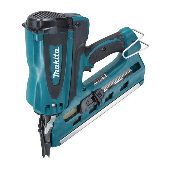
GN900
Cordless Clipped Head Framing Nailer
Battery*
1
Charger
type
quantity
2
BL7010
DC07SA
1
No
No
without Battery and Fuel cell
with Battery and Fuel cell
No
Li-ion
with DC07SA/DC10WA
Clipped-head
2.9 - 3.3
(0.113 - 0.131)
50 - 90
(2 - 3-1/2)
34 degree
44 nails (1 strip)
Coreless DC motor
4,000 nails (approx.)
1,200 nails (approx.)
3.2 (7.0)
3.4 (7.5)
H
Dimensions: mm (")
Length*
(L)
2
Width*
(W)
2
Height (H)
*2 with Hook
7.2
1.0
30
Yes
PRODUCT
P 1/ 16
L
W
321 (12-5/8)
108 (4-1/4)
368 (14-1/2)
Advertisement

Related Manuals for Makita GN900SE


Summary of Contents for Makita GN900SE
- Page 1 Equipped with LED indication lamp with battery power warning and trouble detection functions for convenience of operation and repair This product is available in the following variations. Battery* Model No. Charger type quantity Dimensions: mm (") GN900SE BL7010 DC07SA (Li-ion 1.0Ah) Length* 321 (12-5/8) GN900S GN900ZK Width*...
- Page 2 P 2/ 16 epair CAUTION: 1) Remove Battery, Fuel cell, Nail from the machine for safety before repair/ maintenance in accordance with the instruction manual! 2) Loosen Hex socket head bolts with L-shape wrench in advance before removing them using cordless impact driver with 1R228/ 1R229, or the top of 1R228/ 229 will damage. [1] NECESSARY REPAIRING TOOLS Code No.
- Page 3 P 3/ 16 epair [3] DISASSEMBLY/ASSEMBLY [3]-1. Driver, Front cushion DISASSEMBLING (1) Disassemble Driver complete as illustrated in Figs. 2 and 3. Fig. 2 1) Remove M5x35 Hex socket head bolt (2pcs.) 2) Remove M5x25 Hex socket head bolt (4pcs.) and Top cap. M5x35 Hex socket Housing head bolt (2pcs.)
- Page 4 P 4/ 16 epair [3] DISASSEMBLY/ASSEMBLY [3]-1. Driver, Front cushion (cont.) DISASSEMBLING (2) Separate Cylinder section from Housing. And then disassemble Front cushion. (Fig. 4) Fig. 4 Separate Cylinder section from Housing after removing Insert slotted screwdriver M5x10 Hex socket Arm plate, Contact top and Front plate.
- Page 5 P 5/ 16 epair [3] DISASSEMBLY/ASSEMBLY [3]-2. Exhaust valve section When the tip of Driver complete does not hit the nail head in use, disassemble exhaust valve section to check malfunctions as illustrated in Fig. 8. Fig. 8 Normal condition of Exhaust valve and Exhaust plate Exhaust valve is attached to four holes on Exhaust plate Exhaust plate under Exhaust valve seals Cylinder when Driver complete moves to the lowest position.
- Page 6 P 6/ 16 epair [3] DISASSEMBLY/ASSEMBLY [3]-2. Exhaust valve section (cont.) ASSEMBLING (1) Use slotted screwdriver to scrape away adhesive left on the frame on Cylinder. Note: The incomplete scraping causes the leakage of gas. (2) Take the assembling step as illustrated in Figs. 11 and 12. Fig.
- Page 7 P 7/ 16 epair [3] DISASSEMBLY/ASSEMBLY [3]-3. Chamber DISASSEMBLING (1) Disassemble Handle set from Housing as illustrated in Fig. 2. (2) Remove Contact top, Arm plate and Front plate from Cylinder. Separate Cylinder section from Housing as illustrated in Fig. 4. (3) The removed Cylinder section can be disassembled as illustrated in Figs.
- Page 8 P 8/ 16 epair [3] DISASSEMBLY/ASSEMBLY [3]-3. Chamber (cont.) ASSEMBLING (1) Assemble Cylinder rings to Cylinder as illustrated in Fig. 15. Note: Apply the specific lubricants in accordance with the instruction shown in Fig. 1. Fig. 15 Cylinder ring (2pcs.) Cylinder Assemble Cylinder rings to Cylinder so that the angle of the two notches is more than 90 degrees.
- Page 9 P 9/ 16 epair [3] DISASSEMBLY/ASSEMBLY [3]-4. Pusher, Handle section DISASSEMBLING (1) Separate Handle set from Housing as illustrated in Fig. 2. (2) Handle set (L) can be separated from Handle set (R) as illustrated in Fig. 17. And remove Lock bar and Compression spring 4 as illustrated in Fig.
- Page 10 P 10/ 16 epair [3] DISASSEMBLY/ASSEMBLY [3]-4. Pusher, Handle Section (cont.) DISASSEMBLING (3) Pusher section can be disassembled from Handle set (L) as illustrated in Fig. 19. (4) The other parts in Handle set can be disassembled as illustrated in Fig. 20. Fig.
- Page 11 P 11/ 16 epair [3] DISASSEMBLY/ASSEMBLY [3]-4. Pusher, Handle section (cont.) ASSEMBLING (1) Assemble Pusher section as illustrated in Fig. 21. Fig. 21 Spiral spring Pusher holder complete Spiral spring complete Pusher lever M4x20 Pan head screw Insert drum portion of Pusher Keeping the suitable position, lever into Spiral spring complete, fasten Pusher holder to...
- Page 12 P 12/ 16 epair [3] DISASSEMBLY/ASSEMBLY [3]-5. DC motor and Spark plug DISASSEMBLING (1) Separate Handle set from Housing as illustrated in Fig. 2. (2) Disconnect Spark plug and DC motor from Spark unit and Terminal as illustrated in Fig. 23. (3) DC motor can be removed from Cylinder head as illustrated in Figs.
- Page 13 P 13/ 16 epair [3] DISASSEMBLY/ASSEMBLY [3]-5. DC motor and Spark plug (cont.) ASSEMBLING (1) Assemble DC Motor to Cylinder head as illustrated in Figs. 26, 27 and 27A. Fig. 26 Flat washer 10 Retaining ring R-24 Conical compression spring 12-18 Steel ball 3 Epoxy Motor sleeve...
- Page 14 P 14/ 16 epair [3] DISASSEMBLY/ASSEMBLY [3]-5. DC motor and Spark plug (cont.) ASSEMBLING Note: Conical compression springs 12-18 have to be assembled as mentioned below and shown in Fig. 28. Fig. 28 Top cap side Conical compression spring 12-18 (See the left illustration in Fig.
-
Page 15: Circuit Diagram
P 15/ 16 epair [5] Diagnosis by Indication lamp Color of the indication lamp means the followings. Blinking green: Normal status Blinking red: Need to recharge the battery cartridge Lighting-up-red: Recharge the battery cartridge. Nailing can not be performed due to no remaining battery capacity. Blinking orange after blinking green and red alternatively for 10 seconds: Fault detection is running. -
Page 16: Wiring Diagram
P 16/ 16 iring diagram Fig. D-2 Wiring in Handle set (R) Put lead wire (black) of 70 up to 75 mm Lead wire to Spark plug has to be pulled Spark plug between rib out by 70 up to 75mm from the opening and boss.