Aiwa XR-EM20 Service Manual
Hide thumbs
Also See for XR-EM20:
- Operating instructions manual (20 pages) ,
- Service manual (62 pages)
Table of Contents
Advertisement
QQ
3 7 63 1515 0
SERVICE MANUAL
TE
L 13942296513
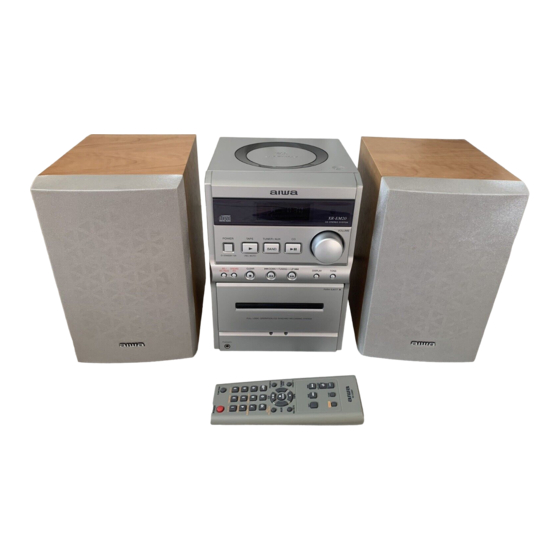
CD STEREO SYSTEM
XR-EM20
• This Service Manual is the "Revision Publishing" and replaces
"Simple Manual" (S/M Code No. 09-022-454-3T1).
www
.
http://www.xiaoyu163.com
COMPACT
SYSTEM
DISC
CX-LEM20
x
ao
y
i
S/M Code No. 09-024-454-3R1
http://www.xiaoyu163.com
XR-EM20
8
Q Q
3
6 7
1 3
BASIC TAPE MECHANISM : CMAL5Z213A
BASIC CD MECHANISM : KSM-213RDM
SPEAKER
SX-LEM20
u163
.
U(S)
2 9
9 4
2 8
1 5
0 5
8
2 9
9 4
REMOTE
CONTROLLER
RC-CAS07
m
co
9 9
2 8
9 9
Advertisement
Table of Contents

Related Manuals for Aiwa XR-EM20


Summary of Contents for Aiwa XR-EM20
- Page 1 XR-EM20 U(S) 3 7 63 1515 0 SERVICE MANUAL L 13942296513 BASIC TAPE MECHANISM : CMAL5Z213A CD STEREO SYSTEM BASIC CD MECHANISM : KSM-213RDM COMPACT REMOTE SYSTEM SPEAKER DISC CONTROLLER XR-EM20 CX-LEM20 SX-LEM20 RC-CAS07 • This Service Manual is the “Revision Publishing” and replaces “Simple Manual”...
-
Page 2: Table Of Contents
http://www.xiaoyu163.com TABLE OF CONTENTS 3 7 63 1515 0 SPECIFICATIONS ................................3 PROTECTION OF EYES FROM LASER BEAM DURING SERVICING ..............4 ELECTRICAL PARTS LIST (CX – LEM20) ......................5 ~ 13 ELECTRICAL PARTS LIST (CZA – 3) ........................14 ~ 16 CHIP RESISTOR PART CODE ............................ -
Page 3: Specifications
http://www.xiaoyu163.com SPECIFICATIONS 3 7 63 1515 0 MAIN UNIT CX-LEM20 GENERAL Power requirements 120 V AC, 60 Hz TUNER Power consumption 26 W FM tuning range 87.5 MHz to 108 MHz Dimensions (W x H x D) 163 x 230 x 215.7 mm FM usable sensitivity (IHF) 13.2 dBf in.) -
Page 4: Protection Of Eyes From Laser Beam During Servicing
http://www.xiaoyu163.com PROTECTION OF EYES FROM LASER BEAM DURING SERVICING 3 7 63 1515 0 CAUTION This set employs laser. Therefore, be sure to follow carefully the instructions below when servicing. Use of controls or adjustments or performance of proce- dures other than those specified herin may result in WARNING!! hazardous radiation exposure. -
Page 5: Electrical Parts List (Cx - Lem20)
http://www.xiaoyu163.com ELECTRICAL PARTS LIST (CX – LEM20) = ! SAFTY PARTS = Components marked All components used on this model at the production line are shown in this service manual. 3 7 63 1515 0 However, please note that not all components will be available as spare parts for after-sales service. Components marked S and O are designated as spare parts for service and will be stocked at the spare parts centers. - Page 6 S IC 0501 87-A20-446-010 C-IC LA9241ML [SANYO] S IC 0551 87-017-917-080 C-IC,BU4066BCF(SOP14) [RO S IC 0581 87-A22-256-040 C-IC CD-DRIVER BA5949FP [ S IC 0851 87-A21-319-01J C-IC LC78622NE DSP [AIWA] 0801 S2-610-000-0KM Fixed Inductor 10 uH +/-1 0501 89-111-625-080 C-TR 2SA1162GR (O.15W)
- Page 7 http://www.xiaoyu163.com = ! SAFTY PARTS = Components marked All components used on this model at the production line are shown in this service manual. 3 7 63 1515 0 However, please note that not all components will be available as spare parts for after-sales service. Components marked S and O are designated as spare parts for service and will be stocked at the spare parts centers.
- Page 8 FRONT 0 FFC0302 S1-204-182-000 FF-CABLE 7P 25mm X 98mm FRONT 0 FL 0301 8C-CL6-608-010 FL,HNA-08SS36T FRONT S IC 0301 8C-CL6-601-01J C-IC,LC876748A-5Z32 [AIWA FRONT S IC 0303 87-A21-245-01C IC RPM6938-V4 REMOTE CONT CX-LEM20 FRONT 0301 87-A50-333-010 COIL CLK 9.43 MHz KHSC-86...
- Page 9 http://www.xiaoyu163.com = ! SAFTY PARTS = Components marked All components used on this model at the production line are shown in this service manual. 3 7 63 1515 0 However, please note that not all components will be available as spare parts for after-sales service. Components marked S and O are designated as spare parts for service and will be stocked at the spare parts centers.
- Page 10 http://www.xiaoyu163.com = ! SAFTY PARTS = Components marked All components used on this model at the production line are shown in this service manual. 3 7 63 1515 0 However, please note that not all components will be available as spare parts for after-sales service. Components marked S and O are designated as spare parts for service and will be stocked at the spare parts centers.
- Page 11 http://www.xiaoyu163.com = ! SAFTY PARTS = Components marked All components used on this model at the production line are shown in this service manual. 3 7 63 1515 0 However, please note that not all components will be available as spare parts for after-sales service. Components marked S and O are designated as spare parts for service and will be stocked at the spare parts centers.
- Page 12 http://www.xiaoyu163.com = ! SAFTY PARTS = Components marked All components used on this model at the production line are shown in this service manual. 3 7 63 1515 0 However, please note that not all components will be available as spare parts for after-sales service. Components marked S and O are designated as spare parts for service and will be stocked at the spare parts centers.
- Page 13 http://www.xiaoyu163.com = ! SAFTY PARTS = Components marked All components used on this model at the production line are shown in this service manual. 3 7 63 1515 0 However, please note that not all components will be available as spare parts for after-sales service. Components marked S and O are designated as spare parts for service and will be stocked at the spare parts centers.
-
Page 14: Electrical Parts List (Cza - 3)
http://www.xiaoyu163.com ELECTRICAL PARTS LIST (CZA – 3) = ! SAFETY PARTS = Components marked All components used on this model at the production line are shown in this service manual. 3 7 63 1515 0 However, please note that not all components will be available as spare parts for after-sales service. Components marked S and O are designated as spare parts for service and will be stocked at the spare parts centers. - Page 15 http://www.xiaoyu163.com = ! SAFETY PARTS = Components marked All components used on this model at the production line are shown in this service manual. 3 7 63 1515 0 However, please note that not all components will be available as spare parts for after-sales service. Components marked S and O are designated as spare parts for service and will be stocked at the spare parts centers.
- Page 16 http://www.xiaoyu163.com = ! SAFETY PARTS = Components marked All components used on this model at the production line are shown in this service manual. 3 7 63 1515 0 However, please note that not all components will be available as spare parts for after-sales service. Components marked S and O are designated as spare parts for service and will be stocked at the spare parts centers.
-
Page 17: Chip Resistor Part Code
http://www.xiaoyu163.com CHIP RESISTOR PART CODE 3 7 63 1515 0 Chip Resistor Part Coding Figure Resistor Code Value of resistor Chip resistor Dimensions (mm) Symbol Wattage Type Tolerance Resistor Code Form 1/16W 1005 0.35 1/16W 1608 0.45 1/10W 2125 1.25 0.45 1/8W 3216... -
Page 18: Wiring - 1 (Main) <1 / 2
http://www.xiaoyu163.com WIRING – 1 (MAIN) <1 / 2> 3 7 6 3 1 5 1 5 0 MAIN C.B J104 (COMPONENT SIDE) PHONES E / RP HEAD J103 SPEAKERS SPEAKER IMP : 6 J101 CNA351 SUB WOOFER 1 3 9 4 2 2 9 6 5 1 3 AUX IN NOTE : RXXX... -
Page 19: Wiring - 1 (Main) <2 / 2
http://www.xiaoyu163.com WIRING – 1 (MAIN) <2 / 2> 3 7 6 3 1 5 1 5 0 MAIN C.B (CONDUCTOR SIDE) 1 3 9 4 2 2 9 6 5 1 3 NOTE : RXXX CXXX JRXXX FBXXX QXXX QXXX w w w u 1 6 3 –... -
Page 20: Schematic Diagram - 1 (Main)
http://www.xiaoyu163.com SCHEMATIC DIAGRAM – 1 (MAIN) 3 7 6 3 1 5 1 5 0 TO TUNER C.B CN991 J101 MAIN C.B AUX IN 035600STY7 SUB WOOFER J104 PHONES Q104, 113, 114 VCC REGULATOR HOLD SW J103 POWER AMP SPEAKERS SPEAKER IMP : 6 SWITCH VOLUME... -
Page 21: Wiring - 2 (Front / Cd) <1 / 2
http://www.xiaoyu163.com WIRING – 2 (FRONT / CD) <1 / 2> 3 7 6 3 1 5 1 5 0 IC303 FRONT C.B CD C.B FL301 REMOTE SW802 (COMPONENT SIDE) SENSOR FL DISPLAY (COMPONENT SIDE) (CD DOOR LEAF SW) VREF 1 2 3 1 3 9 4 2 2 9 6 5 1 3 (FFC302) S301... -
Page 22: Wiring - 2 (Front / Cd) <2 / 2
http://www.xiaoyu163.com WIRING – 2 (FRONT / CD) <2 / 2> 3 7 6 3 1 5 1 5 0 CD C.B FRONT C.B (CONDUCTOR SIDE) (CONDUCTOR SIDE) (VREF) (RF) (TE) 1 3 9 4 2 2 9 6 5 1 3 (FE) NOTE : RXXX... -
Page 23: Schematic Diagram - 2 (Front / Deck)
http://www.xiaoyu163.com SCHEMATIC DIAGRAM – 2 (FRONT / DECK) 3 7 6 3 1 5 1 5 0 FRONT C.B FL DISPLAY REMOTE SENSOR SYNCHRO REC REC/REC PAUSE CLEAR S306 TAPE (REC MUTE) S304 TUNER/AUX/BAND DISPLAY TONE S309 TUNING UP S307 TUNING DOWN S301 POWER... -
Page 24: Schematic Diagram - 3 (Cd / Drive)
http://www.xiaoyu163.com SCHEMATIC DIAGRAM – 3 (CD / DRIVE) 3 7 6 3 1 5 1 5 0 CD C.B RCH-O LCH-O 035600STY7 1 3 9 4 2 2 9 6 5 1 3 035600STY7 L-CH A-GND R-CH D-GND VM(6V) Q501 DRV-GND ADJUST CD-DRF(FOK) -
Page 25: Wiring - 3 (Pt)
http://www.xiaoyu163.com WIRING – 3 (PT) 3 7 63 1515 0 TO MAIN C.B WH101 PT C.B AC 120V 60HZ L 13942296513 u163 – 25 – http://www.xiaoyu163.com... -
Page 26: Schematic Diagram - 4 (Pt)
http://www.xiaoyu163.com SCHEMATIC DIAGRAM – 4 (PT) 3 7 63 1515 0 PT C.B L 13942296513 2.2M 1/2W TERMINAL 1P MSC AC 120V 60HZ NOTE: TERMINAL 1P MSC NM: NO MOUNT u163 – 26 – http://www.xiaoyu163.com... -
Page 27: Wiring - 4 (Tuner)
http://www.xiaoyu163.com WIRING – 4 (TUNER) 3 7 63 1515 0 L 13942296513 u163 – 27 – http://www.xiaoyu163.com... -
Page 28: Schematic Diagram - 5 (Tuner)
http://www.xiaoyu163.com SCHEMATIC DIAGRAM – 5 (TUNER) 3 7 6 3 1 5 1 5 0 1 3 9 4 2 2 9 6 5 1 3 w w w u 1 6 3 – 28 – http://www.xiaoyu163.com... -
Page 29: Wiring - 5 (Deck)
http://www.xiaoyu163.com WIRING – 5 (DECK) 3 7 63 1515 0 CMAL5Z213A DECK C.B L 13942296513 u163 – 29 – http://www.xiaoyu163.com... -
Page 30: Ic Block Diagram
http://www.xiaoyu163.com IC BLOCK DIAGRAM 3 7 6 3 1 5 1 5 0 1 3 9 4 2 2 9 6 5 1 3 w w w u 1 6 3 – 30 – http://www.xiaoyu163.com... -
Page 31: Ic Description
http://www.xiaoyu163.com IC DESCRIPTION IC, LC78622NE 3 7 63 1515 0 Description Pin No. Pin Name DEFI Defect detection signal (DEF) input. ("L" is applied when not used.) For PLL/Test input. (Connected to 0V) Phase comparison output to control the external VCO. VVSS –... - Page 32 http://www.xiaoyu163.com 3 7 63 1515 0 Pin Name Description Pin No. RCHO Rch output. RVDD – Rch power supply. MUTE-R Rch muting output. (Not used) XVDD – Power supply of crystal oscillator. XOUT For the connection of a 16.934MHz crystal oscillator. XVSS –...
- Page 33 http://www.xiaoyu163.com IC, LA9241ML 3 7 63 1515 0 Description Pin No. Pin Name For the connection of the pickup photodiode. Addition to the FIN1 pin creates an RF FIN2 signal and subtraction from it create an EF signal. FIN1 For the connection of the pickup photodiode. For the connection of the pickup photodiode.
- Page 34 http://www.xiaoyu163.com 3 7 63 1515 0 Pin Name Description Pin No. SLOF Sled servo off control input. CV– CLV error signal input from the DSP. RFSM RF output. RFS– Sets the RF gain and the EFM signal's 3T compensation constant together with the RFSM pin. The SLC (slice level control) signal is output to control the DSP's data slice level of the RF waveform.
- Page 35 http://www.xiaoyu163.com IC, LC876748A-5Z32 3 7 63 1515 0 Pin No. Pin Name Description O-COCK CD control Q code clock signal output. O-RWC CD control command LAT signal output. O-CDIN CD control command data signal output. I-WRQ CD control SCOR signal input. I-DRF CD control focus OK input.
- Page 36 http://www.xiaoyu163.com 3 7 63 1515 0 Pin No. Pin Name Description VDD4 – Digital power supply pin. D-VDD – Not used. EZK-VDD – Not used. IN-ECO Not used. 76 ~ 84 – Not connected. KSCAN1 Initial scan I/P. O-MUTE Mute signal output. O-BIAS Bias ON/OFF output.
-
Page 37: Fl (Hna - 08Ss36T) Grid Assignment / Pin Connection / Anode Connection
http://www.xiaoyu163.com FL (HNA – 08SS36T) GRID ASSIGNMENT / PIN CONNECTION / ANODE CONNECTTION GRID ASSIGNMENT 3 7 63 1515 0 PIN CONNECTION L 13942296513 ANODE CONNECTION u163 – 37 – http://www.xiaoyu163.com... -
Page 38: Adjustment (Front / Deck / Tuner / Cd)
http://www.xiaoyu163.com ADJUSTMENT < FRONT / DECK / TUNER / CD > 3 7 63 1515 0 <FRONT SECTION> FRONT C.B (PART SIDE) FRONT C.B (PATTERN SIDE) FL301 IC301 L301 (KSCAN) ① 1. CLOCK ADJUSTMENT Requirement Test point: TP1 (KSCAN1) (IC301 85pin), GND Adjustment point: L301 1) While pressing and holding down the POWER button and the TUNER / BAND button, insert the AC plug to outlet. - Page 39 http://www.xiaoyu163.com 3 7 63 1515 0 <DECK SECTION> MAIN C.B (PART SIDE) E/RP HEAD ①② ③ C651 C652 ③ DECK MECHANISM L451 ④ MOTOR ① J104 L 13942296513 1.TAPE SPEED ADJUSTMENT Requirements Measuring equipments : wow-flutter meter (frequency counter ) Test Tape: TTA-100 (3KHz) Test point: C651(Lch),C652(Rch),GND WOW&FLUTTER METER...
- Page 40 http://www.xiaoyu163.com 3 7 63 1515 0 3.HEAD AZIMUTH ADJUSTMENT Requirements Measuring equipment: Oscilloscope Test Tape: TTA-330 (8KHz) OSCILLOSCOPE Test point: C651(Lch),C652(Rch),GND Adjustment point: Head azimuth screw OUTPUT 1) Connect the Test point to the oscilloscope of CH1 and CH2. 2) Set the V mode of the oscilloscope to ADD. 3) Insert the test tape (TTA-330) , play back the center of the tape and adjustment the head azimuth screw until the waveform of the oscilloscope has reached the maximum when playing back at 8KHz.
- Page 41 http://www.xiaoyu163.com 3 7 63 1515 0 <TUNER SECTION> TUNER C.B (PART SIDE) TUNER C.B (PATTERN SIDE) ① ②③ CN991 GND 2pin CN991 ⑤ ⑥⑦ (LCH) L955 ⑥ TP8 11pin (RCH) IC991 TP9 12pin ⑤ ⑥⑦ L954 ① ② ③ L903 L904 ⑦...
- Page 42 http://www.xiaoyu163.com 3 7 63 1515 0 < AM ADJUSTMENT> For AM adjustment, do wiring and connection as in the following. 60cm Standard Signal Generator Connect to the respective measuring equipment 5.IF ADJUSTMENT Requirement OSCILLOSCOPE Measuring equipment: Oscilloscope or Millivoltmeter Test point: TP8(Lch), TP9(Rch), GND Adjustment point: L802 (1) Adjust the setting of Standard Signal Generator (hereinafter S.S.G.) to 999KHz of 30% variation.
- Page 43 http://www.xiaoyu163.com 3 7 63 1515 0 <FM ADJUSTMENT> For adjusting FM, do wiring function and connection as in the following. Standard Signal Generator Connect to the respective measuring equipment 7.TRACKING ADJUSTMENT Requirement AC MILLIVOLTMETER Measuring equipment: millivoltmeter Test point: TP8(Lch), TP9(Rch), GND Adjustment point: L904 (1) Adjust the S.S.G.
- Page 44 http://www.xiaoyu163.com 3 7 63 1515 0 <CD SECTION> CD C.B (PART SIDE) CD C.B (PATTERN SIDE) ① ②③ ④ Vref ②③ Vref ④ SFR501 ① Perform the adjustments after the main unit enters the test mode. Place the CD mechanism on level ground. Equipment and tools required Measuring equipment Digital multi-meter...
- Page 45 http://www.xiaoyu163.com 3 7 63 1515 0 3.JITTER CHECK 1) While oscilloscope is kept connected in the same test point as in OSCILLOSCOPE step2. RF WAVEFORM CHECK, connect the output terminal of JITTER METER an oscilloscope to the input terminal of the jitter meter. 2) Set the VOLT range selector of oscilloscope to 500mV range or OUTPUT INPUT...
-
Page 46: Voltage Chart
http://www.xiaoyu163.com VOLTAGE CHART 3 7 63 1515 0 1. COMMON Unit:V MAIN C.B Q106 2SB1370E 20.5 11.8 21.0 Q305 2SK2158 Q105 2SC5343GL 20.5 Q308 2SK2158 Q116 2SC5343GL Q307 2SK2158 Q457 2SA1296GR 11.8 11.8 FRONT C.B Q101 2SC5343GL Q301 DTC114EK 11.8 Q103 2SC5343GL Q302 2SA1296GR 11.8... - Page 47 http://www.xiaoyu163.com 3 7 63 1515 0 IC301 LC876748A-5Z32 1PIN 2PIN 3PIN 4PIN 5PIN 6PIN 7PIN 8PIN 9PIN 10PIN (STANDBY) 5.2V 5.2V 11PIN 12PIN 13PIN 14PIN 15PIN 16PIN 17PIN 18PIN 19PIN 20PIN 2.5V 5.3V 2.5V 2.5V 5.3V 3.3V 1.25V 21PIN 22PIN 23PIN 24PIN 25PIN...
- Page 48 http://www.xiaoyu163.com 3 7 63 1515 0 3. REC Q305 2SK2158 -7.0V -18.2V Q454 2SC5343GL 10.3V 4.2V 3.8V Q307 2SK2158 -7.0V -18.2V Q309 2SA1162GR -0.7V Q308 2SK2158 -7.0V -18.2V Q310 2SA1162GR -0.7V Q450 2SC3052F 1.3V 3.6V 0.7V Q453 2SC5343GL 3.8V 10.3V 4.2V Q451 2SC5343GL 0.7V...
- Page 49 http://www.xiaoyu163.com 3 7 63 1515 0 IC851 LC78622NE 1PIN 2PIN 3PIN 4PIN 5PIN 6PIN 7PIN 8PIN 9PIN 10PIN 1.6V 1.9V 4.9V 0.4V 2.5V 2.4V 11PIN 12PIN 13PIN 14PIN 15PIN 16PIN 17PIN 18PIN 19PIN 20PIN 0.4V 0.6V 1.9V 4.9V 21PIN 22PIN 23PIN 24PIN 25PIN...
- Page 50 http://www.xiaoyu163.com 3 7 63 1515 0 5.TUNER (FM) IC301 LC876748A-5Z32 1PIN 2PIN 3PIN 4PIN 5PIN 6PIN 7PIN 8PIN 9PIN 10PIN 0.3V 11PIN 12PIN 13PIN 14PIN 15PIN 16PIN 17PIN 18PIN 19PIN 20PIN 5.1V 5.3V 2.5V 2.5V 5.2V 3.3V 1.5V 21PIN 22PIN 23PIN 24PIN 25PIN...
-
Page 51: Cd Test Mode
http://www.xiaoyu163.com CD TEST MODE 3 7 63 1515 0 1. How to Start the CD Test Mode While pressing the CD FUNCTION button, insert the AC plug to the power outlet. When the test mode started, the message [CD TEST] is displayed. 2. -
Page 52: Mechanical Exploded View
http://www.xiaoyu163.com MECHANICAL EXPLODED VIEW 3 7 63 1515 0 L 13942296513 u163 – 52 – http://www.xiaoyu163.com... -
Page 53: Mechanical Parts List
http://www.xiaoyu163.com MECHANICAL PARTS LIST = ! SAFETY PARTS = Components marked All components used on this model at the production line are shown in this service manual. 3 7 63 1515 0 However, please note that not all components will be available as spare parts for after-sales service. Components marked S and O are designated as spare parts for service and will be stocked at the spare parts centers. -
Page 54: Color Name Table
http://www.xiaoyu163.com 3 7 63 1515 0 COLOR NAME TABLE Basic color symbol Color Basic color symbol Color Basic color symbol Color Black Cream Orange Green Gray Blue Transparent Blue Gold Pink Silver Titan Silver Brown Violet White Transparent White Yellow Transparent Yellow Metallic Blue Light Blue... -
Page 55: Tape Mechanism Exploded View
http://www.xiaoyu163.com TAPE MECHANISM EXPLODED VIEW 3 7 63 1515 0 L 13942296513 u163 – 55 – http://www.xiaoyu163.com... -
Page 56: Tape Mechanism Parts List
http://www.xiaoyu163.com TAPE MECHANISM PARTS LIST = ! SAFETY PARTS = Components marked All components used on this model at the production line are shown in this service manual. 3 7 63 1515 0 However, please note that not all components will be available as spare parts for after-sales service. Components marked S and O are designated as spare parts for service and will be stocked at the spare parts centers. -
Page 57: Accessories Part List
http://www.xiaoyu163.com ACCESSORIES PARTS LIST = ! SAFETY PARTS = Components marked All components used on this model at the production line are shown in this service manual. 3 7 63 1515 0 However, please note that not all components will be available as spare parts for after-sales service. Components marked S and O are designated as spare parts for service and will be stocked at the spare parts centers. -
Page 58: Other Parts List (Cx - Lem20)
http://www.xiaoyu163.com OTHER PARTS LIST (CX – ELM20) = ! SAFETY PARTS = Components marked All components used on this model at the production line are shown in this service manual. 3 7 63 1515 0 However, please note that not all components will be available as spare parts for after-sales service. Components marked S and O are designated as spare parts for service and will be stocked at the spare parts centers. -
Page 59: Other Parts List (Cza - 3)
http://www.xiaoyu163.com OTHER PARTS LIST (CZA – 3) = ! SAFETY PARTS = Components marked All components used on this model at the production line are shown in this service manual. 3 7 63 1515 0 However, please note that not all components will be available as spare parts for after-sales service. Components marked S and O are designated as spare parts for service and will be stocked at the spare parts centers. -
Page 60: General Speaker Disassembly Instructions (For Reference)
http://www.xiaoyu163.com GENERAL SPEAKER DISASSEMBLY INSTRUCTIONS (FOR REFERENCE) 3 7 63 1515 0 Type.1 Type.4 Insert a flat-bladed screwdriver into the position indicated by the TOOLS arrows and remove the panel. Remove the screws of each speaker 1 Plastic head hammer unit and then remove the speaker units. -
Page 61: Speaker Parts List (Sx - Lem20)
Components marked X and R are not designated as spare parts for after sales service, and will not be stocked at the spare parts centers. UNIT-NAME ! C REF-NO PARTS-NO PARTS-NAME SUFFIX&MODEL SX-SLEM20 YJMN OTHERS 8B-CPX-016-010 BADGE,AIWA 27.5 OTHERS 8C-CP5-005-010 TUBE, OTHERS 8C-CP5-007-010 CORD,SPKR O OTHERS 8C-CP5-008-010 CORD,BUSH O OTHERS... -
Page 62: Www Ao Co
http://www.xiaoyu163.com 3 7 63 1515 0 L 13942296513 u163 2-11, IKENOHATA 1-CHOME, TAITO-KU, TOKYO 110-8710, JAPAN TEL:03 (3827) 3111 9301978 9430209 921338 http://www.xiaoyu163.com...