
Related Manuals for Aiwa XR-EM60


Summary of Contents for Aiwa XR-EM60
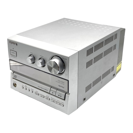
- Page 1 XR-EM60 K(S) XR-EM61 EZ(S) SERVICE MANUAL CD STEREO SYSTEM BASIC CD MECHANISM : 3ZG-3 E13NM REMOTE SYSTEM SPEAKER RECEIVER CONTROLLER XR–EM60 CX–LEM60 SX–LEM60 RC–CAS04 XR–EM61 CX–LEM61 S/M Code No. 09-025-456-0R1...
-
Page 2: Table Of Contents
TABLE OF CONTENTS SPECIFICATIONS ................................3 PROTECTION OF EYES FROM LASER BEAM DURING SERVICING ............... 4 PRECAUTION TO REPLACE OPTICAL BLOCK ......................4 ELECTRICAL PARTS LIST (CX – LEM60 / CX – LEM61) ..................5 ~ 14 ELECTRICAL PARTS LIST (CZA – 3) ........................15 ~ 18 ELECTRICAL PARTS LIST (3ZG –... -
Page 3: Specifications
SPECIFICATIONS MAIN UNIT CX-LEM60 <K>, CX-LEM61 <EZ> CD PLAYER TUNER Laser Semiconductor laser (l = 780 nm) D/A converter 1 bit dual FM tuning range 87.5 MHz to 108 MHz Signal-to-noise ratio 85 dB (1 kHz, 0 dB) FM usable sensitivity (IHF) 16.8 dBf Wow and flutter Unmeasurable FM antenna terminal... -
Page 4: Protection Of Eyes From Laser Beam During Servicing
PROTECTION OF EYES FROM LASER BEAM DURING SERVICING CAUTION This set employs laser. Therefore, be sure to follow carefully the instructions below when servicing. Use of controls or adjustments or performance of proce- dures other than those specified herin may result in WARNING!! hazardous radiation exposure. -
Page 5: Electrical Parts List (Cx - Lem60 / Cx - Lem61)
ELECTRICAL PARTS LIST (CX – LEM60 / CX – LEM61) = ! SAFTY PARTS = Components marked All components used on this model at the production line are shown in this service manual. However, please note that not all components will be available as spare parts for after-sales service. Components marked S and O are designated as spare parts for service and will be stocked at the spare parts centers. - Page 6 = ! SAFTY PARTS = Components marked All components used on this model at the production line are shown in this service manual. However, please note that not all components will be available as spare parts for after-sales service. Components marked S and O are designated as spare parts for service and will be stocked at the spare parts centers. Components marked X and R are not designated as spare parts for after sales service, and will not be stocked at the spare parts centers.
- Page 7 = ! SAFTY PARTS = Components marked All components used on this model at the production line are shown in this service manual. However, please note that not all components will be available as spare parts for after-sales service. Components marked S and O are designated as spare parts for service and will be stocked at the spare parts centers. Components marked X and R are not designated as spare parts for after sales service, and will not be stocked at the spare parts centers.
- Page 8 = ! SAFTY PARTS = Components marked All components used on this model at the production line are shown in this service manual. However, please note that not all components will be available as spare parts for after-sales service. Components marked S and O are designated as spare parts for service and will be stocked at the spare parts centers. Components marked X and R are not designated as spare parts for after sales service, and will not be stocked at the spare parts centers.
- Page 9 = ! SAFTY PARTS = Components marked All components used on this model at the production line are shown in this service manual. However, please note that not all components will be available as spare parts for after-sales service. Components marked S and O are designated as spare parts for service and will be stocked at the spare parts centers. Components marked X and R are not designated as spare parts for after sales service, and will not be stocked at the spare parts centers.
- Page 10 = ! SAFTY PARTS = Components marked All components used on this model at the production line are shown in this service manual. However, please note that not all components will be available as spare parts for after-sales service. Components marked S and O are designated as spare parts for service and will be stocked at the spare parts centers. Components marked X and R are not designated as spare parts for after sales service, and will not be stocked at the spare parts centers.
- Page 11 = ! SAFTY PARTS = Components marked All components used on this model at the production line are shown in this service manual. However, please note that not all components will be available as spare parts for after-sales service. Components marked S and O are designated as spare parts for service and will be stocked at the spare parts centers. Components marked X and R are not designated as spare parts for after sales service, and will not be stocked at the spare parts centers.
- Page 12 = ! SAFTY PARTS = Components marked All components used on this model at the production line are shown in this service manual. However, please note that not all components will be available as spare parts for after-sales service. Components marked S and O are designated as spare parts for service and will be stocked at the spare parts centers. Components marked X and R are not designated as spare parts for after sales service, and will not be stocked at the spare parts centers.
- Page 13 = ! SAFTY PARTS = Components marked All components used on this model at the production line are shown in this service manual. However, please note that not all components will be available as spare parts for after-sales service. Components marked S and O are designated as spare parts for service and will be stocked at the spare parts centers. Components marked X and R are not designated as spare parts for after sales service, and will not be stocked at the spare parts centers.
- Page 14 = ! SAFTY PARTS = Components marked All components used on this model at the production line are shown in this service manual. However, please note that not all components will be available as spare parts for after-sales service. Components marked S and O are designated as spare parts for service and will be stocked at the spare parts centers. Components marked X and R are not designated as spare parts for after sales service, and will not be stocked at the spare parts centers.
-
Page 15: Electrical Parts List (Cza - 3)
ELECTRICAL PARTS LIST (CZA – 3) = ! SAFTY PARTS = Components marked All components used on this model at the production line are shown in this service manual. However, please note that not all components will be available as spare parts for after-sales service. Components marked S and O are designated as spare parts for service and will be stocked at the spare parts centers. - Page 16 = ! SAFTY PARTS = Components marked All components used on this model at the production line are shown in this service manual. However, please note that not all components will be available as spare parts for after-sales service. Components marked S and O are designated as spare parts for service and will be stocked at the spare parts centers. Components marked X and R are not designated as spare parts for after sales service, and will not be stocked at the spare parts centers.
- Page 17 = ! SAFTY PARTS = Components marked All components used on this model at the production line are shown in this service manual. However, please note that not all components will be available as spare parts for after-sales service. Components marked S and O are designated as spare parts for service and will be stocked at the spare parts centers. Components marked X and R are not designated as spare parts for after sales service, and will not be stocked at the spare parts centers.
- Page 18 = ! SAFTY PARTS = Components marked All components used on this model at the production line are shown in this service manual. However, please note that not all components will be available as spare parts for after-sales service. Components marked S and O are designated as spare parts for service and will be stocked at the spare parts centers. Components marked X and R are not designated as spare parts for after sales service, and will not be stocked at the spare parts centers.
-
Page 19: Electrical Parts List (3Zg - 3)
ELECTRICAL PARTS LIST (3ZG – 3) = ! SAFTY PARTS = Components marked All components used on this model at the production line are shown in this service manual. However, please note that not all components will be available as spare parts for after-sales service. Components marked S and O are designated as spare parts for service and will be stocked at the spare parts centers. -
Page 20: Electrical Parts List (3Zg - 2)
ELECTRICAL PARTS LIST (3ZG – 2) = ! SAFTY PARTS = Components marked All components used on this model at the production line are shown in this service manual. However, please note that not all components will be available as spare parts for after-sales service. Components marked S and O are designated as spare parts for service and will be stocked at the spare parts centers. -
Page 21: Chip Resistor Part Code
CHIP RESISTOR PART CODE Chip Resistor Part Coding Figure Resistor Code Value of resistor Chip resistor Dimensions (mm) Symbol Wattage Type Tolerance Resistor Code Form 1/16W 1005 0.35 1/16W 1608 0.45 1/10W 2125 1.25 0.45 1/8W 3216 0.55 TRANSISTOR ILLUSTRATION E C B E C B E C B... -
Page 22: Wiring - 1 (Main)
WIRING – 1 (MAIN) – 22 –... -
Page 23: Schematic Diagram - 1 (Main : 1 / 3 / Hp)
SCHEMATIC DIAGRAM – 1 (MAIN : 1 / 3 / HP) – 23 –... -
Page 24: Schematic Diagram - 2 (Main : 2 / 3
SCHEMATIC DIAGRAM – 2 (MAIN : 2 / 3 <CD SECTION> / CD – DRIVE / CD – LOAD) – 24 –.../ Cd - Drive / Cd - Load) -
Page 25: Schematic Diagram - 3 (Main : 3 / 3
SCHEMATIC DIAGRAM – 3 (MAIN : 3 / 3 <MICON SECTION>) – 25 –...) -
Page 26: Wiring - 2 (Front / Key / Hp)
WIRING – 2 (FRONT / KEY / HP) – 26 –... -
Page 27: Schematic Diagram - 4 (Front / Key)
SCHEMATIC DIAGRAM – 4 (FRONT / KEY) – 27 –... -
Page 28: Wiring - 3 (Amp)
WIRING – 3 (AMP) – 28 –... -
Page 29: Schematic Diagram - 5 (Amp)
SCHEMATIC DIAGRAM – 5 (AMP) – 29 –... -
Page 30: Wiring - 4 (Pt)
WIRING – 4 (PT) – 30 –... -
Page 31: Schematic Diagram - 6 (Pt)
SCHEMATIC DIAGRAM – 6 (PT) – 31 –... -
Page 32: Wiring - 5 (Tuner)
WIRING – 5 (TUNER) – 32 –... -
Page 33: Schematic Diagram - 7 (Tuner)
SCHEMATIC DIAGRAM – 7 (TUNER) – 33 –... -
Page 34: Wiring - 6 (Cd - Drive / Cd - Load)
WIRING – 6 (CD – DRIVE / CD – LOAD) – 34 –... -
Page 35: Fl (Hna - 10Sm19) Grid Assignment / Anode Connection / Pin Connection
FL (HNA – 10SM19) GRID ASSIGNMENT / ANODE CONNECTION / PIN CONNECTION GRID ASSIGNMENT ANODE CONNECTION PIN CONNECTION – 35 –... -
Page 36: Ic Block Diagram
IC BLOCK DIAGRAM – 36 –... - Page 37 – 37 –...
-
Page 38: Ic Description
IC DESCRIPTION IC, LC876748A-5Z30 Pin No. Pin Name Description O-CD DATA CD IC control data output. O-CD ON CD ON/OFF control output. (Not used) O-CD OPEN CD tray open signal output. O-CD CLOSE CD tray close signal output. O-PLL CE PLL IC control chip enable output. - Page 39 Pin No. Pin Name Description I-DEMO OFF Initial DEMO OFF/ON. (Not used) I-ECO OFF Initial ECO OFF/ON. (Connected to pull-down resistor) – Not connected. VDD4 – Power supply. 73 ~ 84 – Not connected. O-TU ON Tuner ON/OFF control output. O-FUNC CLK FUNCTION IC control clock output.
- Page 40 IC, LC78646E Pin No. Pin Name Description SLCO Slice level control output. SLCIST SLCO output current adjustment resistor connection pin. EFMIN RF signal input pin. RF monitor pin. RFVDD – RF power supply pin. RFVSS – RF ground pin. (Connected to 0V) FIN1 A+C signal input pin.
- Page 41 Pin No. Pin Name Description LVDD – Left channel power supply pin. LCHO Left channel output pin. LVSS – Left channel ground pin. (Connected to 0V) RVSS – Right channel ground pin. (Connected to 0V) RCHO Right channel output pin. RVDD –...
- Page 42 IC, LC72131D-N Pin No. Pin Name Description X-IN A crystal oscillator (4.5MHz) is connected between these pins. X-OUT – Not connected. To enable the IC. Active "H". Digital data input from CPU (LC876748A-5Z30) when relevant key is operated. Active "H". To clock in the data DI.
-
Page 43: Adjustment (Tuner / Main)
ADJUSTMENT (TUNER / MAIN) TUNER ADJUSTMENT TUNER C. B (PATTERN SIDE) TUNER C. B (PARTS SIDE) ① ②③ ④ CN991 L952 GND (8pin) ⑥ ⑦⑧ ⑨ CN991 L953 TP8 (11pin) ⑦ TP9 (12pin) IC991 ⑥ ⑦⑧⑨ L941 ① L942 ② ②... - Page 44 5. DC BALANCE CHECK (FM) Requirement Measuring equipment: Digital multi-meter DIGITAL MULTIMETER Test point: TP2, 3 (1) Adjust the reception frequency of the main unit to 98.0MHz. (2) Check that the test point voltage difference between TP2 and TP3 is 0mV ±...
- Page 45 8. TRACKING ADJUSTMENT (LW) Requirement AC MILLIVOLTMETER Measuring equipment: Millivoltmeter Test point: TP8(Lch), TP9(Rch), GND Adjustment point: L941, TC942 (1) Adjust the S.S.G. setting to 144kHz of 30% variation and reduce the output level all the way (till a certain degree of is monitored through the oscilloscope). (2) Adjust the reception frequency of the main unit to 144kHz.
- Page 46 CLOCK ADJUSTMENT AND CD CHECK MAIN C. B (PATTERN SIDE) ① L401 ④ IC301 IC401 Q301 ② ③④ VREF R315 ② ③ ⑥ CLOCK ADJUSTMENT Requirement Test point: CLK, GND Adjustment point: L401 1) While pressing and holding down the POWER button and the TUNER / BAND button, insert the AC plug to outlet.
- Page 47 3. JITTER CHECK 1) While oscilloscope is kept connected in the same test point as in OSCILLOSCOPE step2. RF WAVEFORM CHECK, connect the output terminal of JITTER METER an oscilloscope to the input terminal of the jitter meter. 2) Set the VOLT range selector of oscilloscope to 500mV range or OUTPUT INPUT below.
-
Page 48: Cd Test Mode
CD TEST MODE 1. How to Start the CD Test Mode While pressing the CD PLAY button, insert the AC plug to the power outlet. When the test mode is started, the all indicators light is displayed. 2. How to Exit the CD Test Mode Press the POWER button, push other FUNCTION button or disconnect the AC plug. -
Page 49: Mechanical Exploded View
MECHANICAL EXPLODED VIEW – 49 –... -
Page 50: Mechanical Parts List
8C-CL4-006-010 WINDOW,ASSY DISPLAY X MC1001a 8C-CL4-018-010 WINDOW,DISPLAY K X MC1001a 8C-CL4-005-010 WINDOW,DISPLAY X MC1001b 8C-CL4-209-010 SH,ADH WINDOW O MC1002 8C-CL4-008-010 KNOB,RTRY BT O MC1003 8Z-CC3-007-010 BADGE,AIWA 27.5 ABS SIL O MC1004 8C-CL4-010-010 REFLECTOR,POWER O MC1005 8C-CL4-009-010 KEY,POWER X MC1006 8C-CL4-615-010 PWB,HP... -
Page 51: Color Name Table
COLOR NAME TABLE Basic color symbol Color Basic color symbol Color Basic color symbol Color Black Cream Orange Green Gray Blue Transparent Blue Gold Pink Silver Titan Silver Brown Violet White Transparent White Yellow Transparent Yellow Metallic Blue Light Blue Transparent Green Dark Blue Transparent Orange... -
Page 52: Cd Mechanism Exploded View 1 / 2 <3Zg - 3 E13Nm
CD MECHANISM EXPLODED VIEW 1 / 2 <3ZG – 3 E13NM> – 52 –... -
Page 53: Cd Mechanism Parts List 1 / 2 <3Zg - 3 E13Nm
CD MECHANISM PARTS LIST 1 / 2 <3ZG – 3 E13NM> = ! SAFTY PARTS = Components marked All components used on this model at the production line are shown in this service manual. However, please note that not all components will be available as spare parts for after-sales service. Components marked S and O are designated as spare parts for service and will be stocked at the spare parts centers. -
Page 54: Cd Mechanism Exploded View 2 / 2 <3Zg - 2 E3Nm
CD MECHANISM EXPLODED VIEW 2 / 2 <3ZG – 2 E3NM> – 54 –... -
Page 55: Cd Mechanism Parts List 2 / 2 <3Zg - 2 E3Nm
CD MECHANISM PARTS LIST 2 / 2 <3ZG – 2 E3NM> = ! SAFTY PARTS = Components marked All components used on this model at the production line are shown in this service manual. However, please note that not all components will be available as spare parts for after-sales service. Components marked S and O are designated as spare parts for service and will be stocked at the spare parts centers. -
Page 56: Accessories Parts List
Components marked X and R are not designated as spare parts for after sales service, and will not be stocked at the spare parts centers. UNIT-NAME ! C REF-NO PARTS-NO PARTS-NAME SUFFIX&MODEL CX-LEM60 CX-LEM61 EZSM PRINTED DU 8C-CL4-905-010 IB,K(E)M XR-EM60 PRINTED DU 8C-CL4-906-010 IB,EZ(9L)M XR-EM61 ACCESSORY 8C-CL2-701-010 RC UNIT,RC-CAS04 ACCESSORY 87-A92-346-010 ANT,WIRE FM(FASTEN) ACCESSORY 87-006-226-010 ANT,LOOP AM... -
Page 57: Other Parts List (Cx - Lem60 / Cx - Lem61)
OTHER PARTS LIST (CX – LEM60 / CX – LEM61) = ! SAFTY PARTS = Components marked All components used on this model at the production line are shown in this service manual. However, please note that not all components will be available as spare parts for after-sales service. Components marked S and O are designated as spare parts for service and will be stocked at the spare parts centers. -
Page 58: Other Parts List (Cza - 3)
OTHER PARTS LIST (CZA – 3) = ! SAFTY PARTS = Components marked All components used on this model at the production line are shown in this service manual. However, please note that not all components will be available as spare parts for after-sales service. Components marked S and O are designated as spare parts for service and will be stocked at the spare parts centers. -
Page 59: Other Parts List (3Zg - 3)
OTHER PARTS LIST (3ZG – 3) = ! SAFTY PARTS = Components marked All components used on this model at the production line are shown in this service manual. However, please note that not all components will be available as spare parts for after-sales service. Components marked S and O are designated as spare parts for service and will be stocked at the spare parts centers. -
Page 60: Other Parts List (3Zg - 2)
OTHER PARTS LIST (3ZG – 2) = ! SAFTY PARTS = Components marked All components used on this model at the production line are shown in this service manual. However, please note that not all components will be available as spare parts for after-sales service. Components marked S and O are designated as spare parts for service and will be stocked at the spare parts centers. -
Page 61: General Speaker Disassembly Instructions (For Reference)
GENERAL SPEAKER DISASSEMBLY INSTRUCTIONS (FOR REFERENCE) Type.1 Type.4 Insert a flat-bladed screwdriver into the position indicated by the TOOLS arrows and remove the panel. Remove the screws of each speaker 1 Plastic head hammer unit and then remove the speaker units. 2 (() flat head screwdriver 3 Cut chisel How to Remove the PANEL, FR... -
Page 62: Speaker Parts List (Sx - Lem60)
YJMN OTHERS 8A-CJ5-415-010 TERMINAL, OTHERS 8B-CP5-610-010 CORD,SPKR OTHERS 8B-CPX-001-010 TUBE,40 OTHERS 8B-CPX-005-010 GRILLE,FRAME OTHERS 8B-CPX-009-010 CUSHION,FELT OTHERS 8B-CPX-016-010 BADGE,AIWA 27.5 OTHERS 8C-CP4-001-010 RING,W OTHERS 8C-CP4-002-010 RING,TW OTHERS 8C-CP4-004-010 GRILLE,FRAME ASSY OTHERS 8C-CP4-005-010 NET, OTHERS 8C-CP4-006-010 LBL,SPEC YJ OTHERS 8C-CP4-602-010 SPKR, W 120 25/2... - Page 63 2-11, IKENOHATA 1-CHOME, TAITO-KU, TOKYO 110-8710, JAPAN TEL:03 (3827) 3111 9420025 921338...