ATEN CS9134 User Manual
4 port/ 8 port kvm switch
Hide thumbs
Also See for CS9134:
- User manual (34 pages) ,
- User manual (31 pages) ,
- User manual (31 pages)
Table of Contents
Advertisement
Quick Links
Advertisement
Table of Contents

Related Manuals for ATEN CS9134


Summary of Contents for ATEN CS9134
- Page 1 4 Port / 8 Port KVM Switch CS9134 / CS9138 User Manual www.aten.com...
-
Page 2: Fcc Information
CS9134 / CS9138 User Manual FCC Information This is an FCC Class A product. In a domestic environment this product may cause radio interference in which case the user may be required to take adequate measures. This equipment has been tested and found to comply with the limits for a Class A digital device, pursuant to Part 15 of the FCC Rules. -
Page 3: User Information
The manufacturer is not responsible for any damage incurred in the operation of this system if the correct operational voltage setting was not selected prior to operation. PLEASE VERIFY THAT THE VOLTAGE SETTING IS CORRECT BEFORE USE. CS9134 / CS9138 User Manual... -
Page 4: Safety Instructions
CS9134 / CS9138 User Manual Safety Instructions General Read all of these instructions. Save them for future reference. Follow all warnings and instructions marked on the device. Do not place the device on any unstable surface (cart, stand, table, etc.). If the device falls, serious damage will result. - Page 5 The device does not operate normally when the operating instructions are followed. Only adjust those controls that are covered in the operating instructions. Improper adjustment of other controls may result in damage that will require extensive work by a qualified technician to repair. CS9134 / CS9138 User Manual...
-
Page 6: Rack Mounting
CS9134 / CS9138 User Manual Rack Mounting Before working on the rack, make sure that the stabilizers are secured to the rack, extended to the floor, and that the full weight of the rack rests on the floor. Install front and side stabilizers on a single rack or front stabilizers for joined multiple racks before working on the rack. -
Page 7: Package Contents
* Features may have been added to the CS9134 / CS9138 since this manual was printed. Please visit our website to download the most up to date version of the manual. -
Page 8: Table Of Contents
CS9134 ........ - Page 9 CS9134 ........
-
Page 10: About This Manual
CS9134 / CS9138. Chapter 4, OSD Operation, provides a complete description of the CS9134 / CS9138’s OSD (On Screen Display), and how to work with it. An Appendix, at the end of the manual provides specifications and other... -
Page 11: Conventions
ATEN on the Web or contact an ATEN Authorized Reseller. Visit ATEN on the Web for a list of locations and telephone numbers International – http://www.aten.com North America – http://www.aten-usa.com CS9134 / CS9138 User Manual → Run means to... -
Page 12: Technical Support
CS9134 / CS9138 User Manual Technical Support International Email Support Online Support Technical Support Troubleshooting Documentation Software Updates North America Email Support Online Support Technical Support Troubleshooting Documentation Software Updates When you contact us, please have the following information ready beforehand: Product model number, serial number, and date of purchase. -
Page 13: Introduction
CS9138, you can easily access multiple computers in a cost effective manner. A single Master View CS9134 or CS9138 can control up to 4 or 8 computers, respectively. Since the switches can be cascaded to three levels, in a full three... -
Page 14: Features
CS9134 / CS9138 User Manual Features Cascadable To Three Levels - Control Up to 64 (CS9134) or 512 (CS9138) Computers From a Single Console No Software Required - Computer Selection via Front Panel Switches, Hot Keys, or OSD (On Screen Display) -
Page 15: Hardware Requirements
Hardware Requirements Console A VGA, SVGA, or Multisync monitor capable of the highest resolution that you will be using on any computer in the installation A PS/2 style keyboard A PS/2 style mouse Computers The following equipment must be installed on each computer that is to be connected to the system: A VGA, SVGA or Multisync port. -
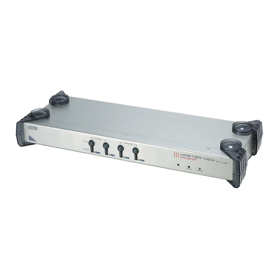
Page 16: Components
CS9134 / CS9138 User Manual Components Front View CS9134 CS9138 K/M RESET K/M RESET AUTO SCAN AUTO SCAN... - Page 17 Component Port Selection Switches Port LEDs The Port LEDs are built into the Port Selection Switches. The upper ones are the On Line LEDs; the lower ones are the Selected Port LEDs: Sound Opening System sounds (beeps, etc.) are emitted from this opening.
-
Page 18: Rear View
CS9134 / CS9138 User Manual Rear View CS9134 CS9138 Component Power Jack Console Port Section Computer Port Section Description The unit is designed to be non-powered (external power is not required - its operating power comes from the computers). In general, the only time that external power is... -
Page 19: Hardware Setup
Stacking and Rack Mounting Stacking CS9134 / CS9138 switches can be stacked one on top of the other using the stacking brackets that come already attached to the unit. Line up the four bottom brackets of the top unit with the four top brackets of the bottom unit;... -
Page 20: Rack Mounting
CS9134 / CS9138 User Manual Rack Mounting 1. Remove the stacking brackets by unscrewing them from the unit, as shown in the diagram below: 2. Screw the mounting brackets into the sides of the unit, as shown in the diagram below:... -
Page 21: Single Station Installation
Single Station Installation In a Single Stage installation, there are no additional Master View's cascaded down from the first unit. To set up a single stage installation do the following: 1. Plug your keyboard, mouse, and monitor into the unit's Console Ports. 2. -
Page 22: Two Stage Installation
Stage unit. The cascaded Master Views that connect back to the First Stage unit are considered Second Stage units. As many as 16 (CS9134) or 64 (CS9138) computers can be controlled in a complete two stage installation. Tables showing the relation between the number of computers and the number of Master View units needed to control them are provided in the Appendix. -
Page 23: Two Stage Installation Diagram
6. Turn on the power to all the computers. Note: The Power On sequence requires that all Second Stage units be powered on first. After all the Second Stage units have been powered on, the First Stage unit must be powered on next. After the Second and First stage units have been powered on, the computers can be powered on. -
Page 24: Three Stage Installation
The procedures for setting up a three stage installation are essentially the same as for a two stage installation. With a three stage setup, as many as 64 (CS9134) or 512 (CS9138) computers can be controlled in a complete installation. A table showing the relation between the number of computers and the number of Master View units needed to control them is provided in the Appendix. -
Page 25: Three Stage Installation Diagram
2. Hardware Setup Three Stage Installation Diagram:... - Page 26 CS9134 / CS9138 User Manual This Page Intentionally Left Blank...
-
Page 27: Basic Operation
Hot Plugging The Master View CS9134 / CS9138 supports hot plugging. Components can be removed and added back into the installation by unplugging and replugging their cables from their respective ports without the need to shut the switch down. For hot plugging to work properly, the following procedures must be... -
Page 28: Powering Off And Restarting
Toggling the Buzzer The CS9134 / CS9138 system buzzer can be toggled on and off with a hotkey combination as follows: 1. Press [Ctrl] [Shift] [Alt] to invoke the hotkey function. -
Page 29: Port Selection
Port Selection The Master View CS9134 / CS9138 provides three methods to obtain instant access to any computer in your installation: Manual, Hotkey, and OSD. Manual Port Selection Port Selection: Press the Port Selection Switch on the CS-9134 / CS-9138's front panel that corresponds to the KVM port you want to access. -
Page 30: Hotkey Port Selection
CS9134 / CS9138 User Manual Hotkey Port Selection Port Selection: To select a port with the hotkey method, do the following: 1. Press [Ctrl] [Shift] [Alt] to invoke the hotkey function. 2. Key in the Port ID number (see page 19), then press [Enter]. -
Page 31: Port Id Numbering
A computer attached to a First Stage unit has a one digit Port ID (from 1 to 4 for the CS9134; from 1 to 8 for the CS9138). The number corresponds to the KVM Port number that the computer is connected to. -
Page 32: Port Key In Examples
CS9134 / CS9138 User Manual Port Key In Examples 1. To access a computer attached to port 3 of a Single Stage installation, after invoking hotkey mode, key in 3 for the Port ID, as follows: [Ctrl] [Shift] [Alt] 3 [Enter] 2. -
Page 33: Osd Operation
OSD Overview The On Screen Display (OSD) provides a menu driven interface to handle all computer control and switching procedures. Although Hotkey switching still works, using OSD is a great deal more convenient - especially in large, cascaded installations where it is difficult to keep track of which port a particular computer is attached to. -
Page 34: Osd Navigation
CS9134 / CS9138 User Manual OSD Navigation [Esc] cancels the current selection, or dismisses the current menu and moves back to the menu one level above. If you are at the highest menu level, it deactivates OSD. To move up or down through the list one line at a time, click the Up and Down Triangle symbols ( there are more items than appear on the screen, the screen will scroll. -
Page 35: The Function Keys
The Function Keys Pressing a Function Key brings up a submenu that is used to configure and control the OSD. For example, you can: rapidly switch to any port; scan selected ports only; limit the list you wish to view; designate a port for Quick View scanning;... -
Page 36: F3 List
CS9134 / CS9138 User Manual F3 LIST This function lets you broaden or narrow the scope of which ports the OSD lists. On the submenu that appears, an icon of a pointing finger indicates the currently selected choice. To change a setting, move the highlight bar to the choice you want, then press [Enter]. -
Page 37: F5 Edit
F5 EDIT To help remember which computer is attached to a particular port, every port can be given a name. The EDIT function allows you to create, modify, or delete port names. To edit a port name: 1. Move the highlight bar to the port you want to edit. 2. -
Page 38: F6 Set
CS9134 / CS9138 User Manual F6 SET Pressing [F6] brings up the OSD configuration menu. To change a setting: 1. Move the highlight bar to the choice you want (an icon of a pointing finger indicates which choice is the currently selected one), then press [Enter]. - Page 39 Setting CLEAR THE NAME LIST* RESTORE DEFAULT VALUES* LOCK CONSOLE* * If a password has been set, this setting requires you to supply it in order to gain access. See SET PASSWORD, page 26, and OSD Security, page 28, for details.
-
Page 40: Factory Default Settings
CS9134 / CS9138 User Manual Factory Default Settings The factory default settings are as follows: Setting Display Duration Always On Display Mode The Port Number plus the Port Name Scan Duration 3 Seconds OSD Security In order to prevent unauthorized access to the systems, the OSD provides a password security feature. -
Page 41: Changing A Password
in which case you must start again from the beginning. Changing a Password To change a password: 1. Follow steps 1 and 2 of the Setting a New Password section. 2. Delete the old password; key in the new password, then press [Enter]. As mentioned above, the password may be up to 8 characters long, and can consist of any combination of letters and numbers (Aa - Zz, 0 - 9). - Page 42 CS9134 / CS9138 User Manual This Page Intentionally Left Blank...
-
Page 43: Appendix
Computer Connection Tables The following tables indicate the relationship between the number of Master View Units and the number of systems that they control: CS9138 Comps 8-15 15 - 22 22 - 29 29 - 36 36 - 43 43 - 50 50 - 57 57 - 64 64 - 71... -
Page 44: Cs9134
CS9134 / CS9138 User Manual CS9134 Comps 4 - 7 7 - 10 10 - 13 13 - 16 16 - 19 Compatible Cascade Switches The following ATEN Master View KVM switches can be cascaded from the CS9134 / CS9138:... -
Page 45: Troubleshooting
Troubleshooting Symptom Possible Cause Erratic Unit not receiving behavior. enough power under self powered operation. Pressing the The connection Hotkeys gets from the selected no response. port to the target computer has been broken, or the computer is turned OFF. Improper keyboard reset. -
Page 46: Specifications
CS9134 / CS9138 User Manual Specifications Function Computer Direct Connections Port Selection Connectors Console Computer LEDs Power On Line Selected Video Scan Interval Power Consumption Environment Operating Temp. Storage Temp. Humidity Physical Housing Properties Weight (kg) Dimensions (L x W x H) -
Page 47: Index
Auto Scanning , 17, 18 Compatible Cascade Switches, 32 Components Front View, 4 Rear View, 6 Computer Connection Tables, 31 Factory Default Settings, 28 Features, 2 Hot Plugging, 15 Installation Single Station, 9 Three Stage, 12 Two Stage, 10 Online Registration, iii Function Keys, 23 Main Screen Headings, 22...