Table of Contents
Advertisement
Quick Links
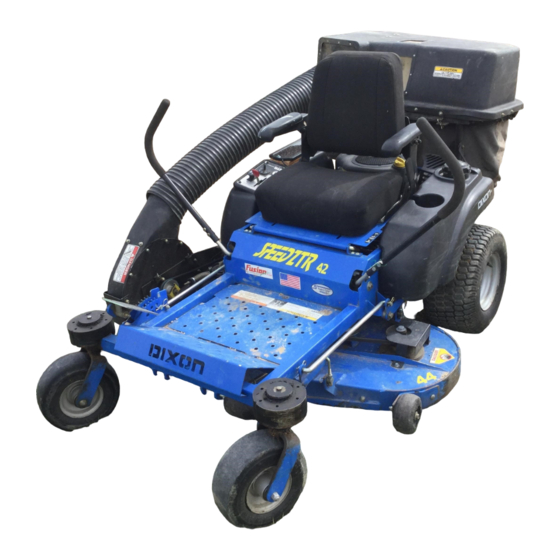
Operator Manual
SPDZTR 42 / 966657601
SPDZTR 46 / 966657801
SPDZTR 46 BF / 966658001
SPDZTR 54 / 966658201
SPDZTR 42 BF / 966657701
SPDZTR 46 CA / 966657901
SPDZTR 48 / 966698601
SPDZTR 54 / 966658301
SPDZTR 54 BF / 966658401
Please read the operator's manual carefully and make sure you
understand the instructions before using the machine.
Advertisement
Table of Contents

Related Manuals for Dixon SPDZTR 42


Summary of Contents for Dixon SPDZTR 42
- Page 1 Operator Manual SPDZTR 42 / 966657601 SPDZTR 42 BF / 966657701 SPDZTR 46 / 966657801 SPDZTR 46 CA / 966657901 SPDZTR 46 BF / 966658001 SPDZTR 48 / 966698601 SPDZTR 54 / 966658201 SPDZTR 54 / 966658301 SPDZTR 54 BF / 966658401 Please read the operator’s manual carefully and make sure you...
- Page 2 When this product is worn out and no longer used, it should be returned to the reseller or other party for recycling. In order to implement improvements, specifications and designs can be altered without prior notification. Note that no legal demands can be placed based on the information contained in these instructions. Use only original parts for repairs.
-
Page 3: Table Of Contents
COntentS IntRODUCtIOn ............5 mowing tips .............31 Driving and transport on Public Roads .....5 Stopping the engine .........32 towing ..............5 manual transport..........33 Operating ............5 mAIntenAnCe ............34 Good Service .............6 maintenance Schedule ........34 SymbOlS AnD DeCAlS .........7 battery ..............36 SAfety ..............9 Safety System ...........37 Safety Instructions ..........9 fuel Pump Air filter ..........37 Personal Safety equipment ......11... - Page 4 WARNING! Failure to follow cautious operating practices can result in serious injury to the operator or other persons. The owner must understand these instructions, and must allow only trained persons who understand these instructions to operate the mower. Each person operating the mower must be of sound mind and body and must not be under the influence of any mind altering substance.
-
Page 5: Introduction
IntRODUCtIOn Congratulations Towing thank you for purchasing a Dixon ride-on mower. If machine is equipped with a tow hitch, use extreme this machine is built for superior efficiency to caution when towing. never allow children or others in rapidly mow primarily large areas. A control panel or on the towed equipment. -
Page 6: Good Service
IntRODUCtIOn Good Service Dixon's products are sold only in specialized retail stores with complete service. this ensures that you as a customer receive only the best support and service. before the product is delivered, the machine has, for example, been inspected and adjusted by your retailer. -
Page 7: Symbols And Decals
SymbOlS AnD DeCAlS these symbols are found on the machine and in the operator’s manual. Study them carefully so that you know what they mean. IMPORTANT INFORMATION WARNING! Xxxx xxxxxx xxxxx xxxx xxxxxxxxx xxxxxx Xxxx xxxxxx xxxxx xxxx xxxxxxxxx xxxxxxxxx. xx xxxxxxxx xxxx xxxxxx. xxxxxx xxxxxxxxx. - Page 8 SymbOlS AnD DeCAlS Read Shut off engine and Keep a safe Use on slopes no passengers Operator’s remove key before distance from no greater manual performing any the machine than 10° maintenance or repair work Whole body Severing of fingers Do not open or Careful backing up, Careful going...
-
Page 9: Safety
SAfety Safety Instructions these instructions are for your safety. Read them carefully. WARNING! This symbol means that important safety instructions need to be emphasized. It concerns your safety. IMPORTANT: tHIS CUttInG mACHIne IS CAPAble Of AmPUtAtInG HAnDS AnD feet AnD tHROWInG ObJeCtS. - Page 10 SAfety • Do not operate the machine while under the influence of alcohol or drugs. • Watch for traffic when operating near or crossing roadways. • Use extra care when loading or unloading the machine into a trailer or truck. •...
-
Page 11: Personal Safety Equipment
SAfety Personal Safety Equipment WARNING! When using the machine, approved personal protective equipment (shown in illustrations) shall be used. Personal protective equipment cannot eliminate the risk of injury but it will reduce the degree of injury if an accident does happen. Ask your retailer for help in choosing the right equipment. - Page 12 SAfety Children tragic accidents can occur if the operator is not alert to the presence of children. Children are often attracted to the machine and the mowing activity. Never assume that children will remain where you last saw them. • Keep children out of the mowing area and in the watchful care of a responsible adult other than the operator.
-
Page 13: Safe Handling Of Gasoline
SAfety WARNING! The engine must not be started when the driver’s floor plate or any protective plate for the mower deck’s drive belt is removed. Safe Handling of Gasoline to avoid personal injury or property damage, use extreme care in handling gasoline. Gasoline is extremely flammable and the vapors are explosive. -
Page 14: General Maintenance
SAfety General Maintenance • never operate machine in a closed area. • Keep all nuts and bolts tight to be sure the equipment is in safe working condition. • never tamper with safety devices. Check their proper operation regularly. • Keep machine free of grass, leaves, or other debris buildup. - Page 15 SAfety Sparking can occur when working with the battery and the heavy cables of the starter circuit. this can cause battery explosion, fire or eye injury. Sparking in this circuit can not occur after the chassis cable (normally negative, black) is removed from the battery. WARNING! Avoid electrical sparking and its consequences by the following...
-
Page 16: Transport
SAfety • Regularly clean deck and underside of deck, avoid spraying engine and electrical components with water. Transport • the machine is heavy and can cause serious crushing injuries. be extra cautious when it is loaded on or unloaded from a vehicle or trailer. •... -
Page 17: Controls
COntROlS this operator’s manual describes the Dixon Zero turn driven hydraulic pumps. Using the left and right Rider. the rider is fitted with either a briggs & Stratton steering controls, the flow is regulated and thereby the or Kawasaki four-stroke overhead valve engine. -
Page 18: Steering Control Levers
COntROlS Steering Control Levers the machine’s speed and direction are continuously variable using the two steering controls. the steering controls can be moved forward or backward about a neutral position. furthermore, there is a neutral position, which is locked if the steering controls are moved outward. -
Page 19: Parking Brake
COntROlS Parking Brake IMPORTANT INFORMATION The machine must stand absolutely still when applying the parking brake. Always set the parking brake before dismounting. Release the parking brake before moving the mower. the parking brake is found on the left of the machine. Push the release button and pull the lever backward to activate the brake—push forward to release it. -
Page 20: Ignition Switch
COntROlS Ignition Switch the ignition switch is placed on the control panel and is used to start and stop the engine. 8058-134 Ignition switch Choke Control the choke control is used for cold starts in order to provide the engine with a richer fuel mixture. for cold starts on models with separate choke, the control on should be pulled out. -
Page 21: Fuel Tank
COntROlS Fuel Tank Read the safety instructions before refueling. the machine has one fuel tank, just behind the console. the tank capacity is 3 gallons (11.4 liters). Regularly check the gas cap gasket for damage and keep the cap properly tightened. the engine will run on a minimum of 85-octane unleaded gasoline (no oil mix). -
Page 22: Fuel Shut Off Valve
COntROlS Fuel Shut Off Valve the fuel shut off valve is located at the left rear of the seat. the valve is off when the handle tab is turned perpendicular to the fuel line. 8011-419 IMPORTANT INFORMATION Fuel shut off valve in the CLOSED position Always raise the deck to the highest position for transport. -
Page 23: Seat Adjustment Lever
COntROlS Seat Adjustment Lever the seat can be adjusted lengthways. When making adjustments, the lever under the right side of the seat is pulled up, after which the seat can be moved backward or forward. 8058-023 Lengthways adjustment Hour Meter the hour meter displays the total operating time. -
Page 24: Operation
OPeRAtIOn Read the Safety section and following pages, if you Steering are unfamiliar with the machine. To move forward and backward Training the direction and speed of the mower’s movements are effected by the movement of the control lever(s) Due to unique steering capabilities, zero turn mowers on each side of mower. -
Page 25: Before Starting
OPeRAtIOn then by alternating one lever slightly to the forward position and the other in the reverse position. Before Starting • Read the sections Safety Instructions and Controls before starting the machine. • Perform the daily maintenance before starting (see maintenance Schedule in the maintenance section). - Page 26 OPeRAtIOn move the steering controls outward to the locked (outer) neutral position. 8058-077 Place controls in neutral position move the throttle to the middle position. 8058-148 Set the throttle If the engine is cold, the choke control should be pulled up. 8058-134 Set the choke control...
- Page 27 OPeRAtIOn Press in and turn the ignition key to the start position. IMPORTANT INFORMATION Do not run the starter for more than 5 seconds 8050-780 each time. If the engine does not start, wait Turn to the start position approximately 10 seconds before retrying. When the engine starts, immediately release the ignition key back to the run position.
-
Page 28: Jumper Cables
OPeRAtIOn Weak Battery WARNING! Lead-acid batteries generate explosive gases. Keep sparks, flame and smoking materials away from batteries. Always wear eye protection when around batteries. IMPORTANT INFORMATION Your mower is equipped with a 12-volt negative grounded system. The other vehicle must also be a 12-volt negative grounded system. -
Page 29: Running
OPeRAtIOn Running Release the parking brake by pushing the top release button in and moving the lever downward. nOte: the mower is equipped with an operator presence system. When the engine is running, any attempt by the operator to leave the seat without first setting the parking brake will shut off the engine. -
Page 30: Operating On Hills
OPeRAtIOn move throttle control to full throttle. engage the mower deck by pulling out the blade switch. the machine’s speed and direction are continuously variable using the two steering controls. When both controls are in the neutral position, the machine stands still. -
Page 31: Mowing Tips
OPeRAtIOn Mowing Tips WARNING! • Observe and flag rocks and other fixed objects to avoid collisions. Clear the lawn of stones and other objects that can be thrown out by the • begin with a high cutting height and reduce it blades. -
Page 32: Stopping The Engine
OPeRAtIOn Stopping the Engine Allow the engine to idle a minute in order to attain normal operating temperature before stopping it, if it has been worked hard. Avoid idling the engine for longer periods, as there is a risk of the spark plugs fouling. -
Page 33: Manual Transport
OPeRAtIOn Manual Transport When pushing or pulling the mower, engage the eZt (Integrated Zeroturn transaxle) bypass linkages. the eZt bypass linkages are located on the rear of the frame, below the rear engine guard. Raise the deck into the highest cutting position. -
Page 34: Maintenance
mAIntenAnCe Maintenance Schedule the following is a list of maintenance procedures that must be performed on the machine. for those points not described in this manual, visit an authorized service workshop. An annual service carried out by an authorized service workshop is recommended to maintain your machine in the best possible condition and to ensure safe operation. - Page 35 mAIntenAnCe Daily At least Maintenance once interval each in hours year MAINTENANCE Before After ■ Check/adjust throttle cable ● ● Check the condition of belts, belt pulleys ■ ■ Change the engine oil ■ ■ Replace the engine oil filter ■...
-
Page 36: Battery
mAIntenAnCe Battery STANDARD STATE APPROXIMATE BATTERY CHARGING TIME* TO FULL CHARGE AT 80 F / 27 your mower is equipped with a maintenance free BATTERY Maximum Rate at: battery and does not need servicing. However, CHARGE 50 Amps 30 Amps 20 Amps 10 Amps periodic charging of the battery with an automotive... -
Page 37: Safety System
Visually check that no damage is found on the lever, cables, or switch belonging to the parking brake. Perform a standstill test and check that there is sufficient braking action. to adjust the parking brake, contact the Dixon service workshop. IMPORTANT INFORMATION The machine must be absolutely standing still when applying the parking brake. -
Page 38: V-Belts
mAIntenAnCe V-belts Check every 100 hours of operation. Check for severe cracking and large nicks. nOte: the belt will show some small cracks in normal operation. the belts are not adjustable. Replace belts if they begin to slip from wear. Deck Belt Park on a level surface. -
Page 39: Cutting Blades
90 ft/lbs (122 nm). 8058-027 IMPORTANT INFORMATION blade blade bolt (special) Special blade bolt is heat treated. Cutter housing Replace with a Dixon bolt if required. Blade attachment Do not use lower grade hardware than specified. -
Page 40: Adjusting The Mower Deck
mAIntenAnCe Adjusting the Mower Deck Leveling deck Adjust the deck while the mower is on a level surface. make sure the tires are inflated to the correct pressure. See Technical Data under Transmission. If tires are under or over inflated, the deck cannot be properly adjusted. -
Page 41: Anti-Scalp Rollers
mAIntenAnCe Anti-scalp Rollers IMPORTANT INFORMATION Adjust anti-scalp rollers with the mower on a flat level surface. Anti-scalp rollers are properly adjusted when they are just slightly off of the ground when the deck is at the desired cutting height in the operating position. Anti- scalp rollers then keep the deck in the proper position to help prevent scalping in most terrain conditions. -
Page 42: Caster Wheels
mAIntenAnCe Caster Wheels Check every 200 hours. Check that wheels rotate freely. If wheels do not rotate freely take the unit to your dealer for service. foam filled tires or solid tires will void the warranty. Removal and installation Remove nut and caster bolt. Pull the wheel out of the yoke and take care of the spacers. -
Page 43: Lubrication
lUbRICAtIOn 8050-832 12/12 every year lubricate with grease gun filter change 1/52 every Week Oil change level check 1/365 every day General Remove the ignition key to prevent unintentional Wipe away excess grease after lubrication. movements during lubrication. It is important to avoid getting lubricant on the belts When lubricating with an oil can, it must be filled with or the drive surfaces on the belt pulleys. -
Page 44: Front Wheel Mount
2-3 strokes per spindle. 8058-136 Deck spindle Transmission the transmission is maintenance free with no need for level checks or oil changes. If a leak occurs, replace the unit or contact your Dixon dealer. -
Page 45: Troubleshooting
tROUbleSHOOtInG Problem Cause engine will not start • blade switch is engaged. • Steering controls are not locked in the neutral position • Parking brake is not activated • battery is dead • Contamination in the carburetor or fuel line. •... - Page 46 tROUbleSHOOtInG Problem Cause engine overheats • Clogged air intake or cooling fins • engine overloaded • Poor ventilation around engine • Defective engine speed regulator • too little or no oil in the engine • Contamination in the carburetor or fuel line. •...
-
Page 47: Storage
Drain the fuel into Always use genuine Dixon spare parts. an approved container outdoors and An annual check-up at an authorized service store far away from open flame or workshop is a good way to ensure that your machine sources of ignition. -
Page 48: Schematics
SCHemAtICS... -
Page 49: Technical Data
teCHnICAl DAtA 966657601 966657701 Engine manufacturer Kawaskai briggs & Stratton type fR 651-V Power 22 hp 22 hp (1,2 (1,2 lubrication Pressure with oil filter Pressure with oil filter fuel min 87 octane unleaded (max min 87 octane unleaded (max ethanol 10%, max mtbe 15%) ethanol 10%, max mtbe 15%) fuel tank capacity... - Page 50 teCHnICAl DAtA 966657601 966657701 Frame Cutting Width 42" / 107cm 42" / 107cm Cutting Height 1.5 - 4" / 3.8 - 10.2 cm 1.5 - 4" / 3.8 - 10.2 cm Uncut Circle number of blades blade length 22¾" / 57.8 cm 22¾"...
- Page 51 teCHnICAl DAtA 966657201, 966657901 966698601 966658001 Engine manufacturer briggs & Stratton Kohler type Courage Power 22 hp 24 hp (1,2 (1,2 lubrication Pressure with oil filter Pressure with oil filter fuel min 87 octane unleaded (max min 87 octane unleaded (max ethanol 10%, max mtbe 15%) ethanol 10%, max mtbe 15%) fuel tank capacity...
- Page 52 TECHNICAL DATA 966657801, 966657901 966698601 966658001 Engine Manufacturer Briggs & Stratton Kohler Type Courage Power 22 hp 24 hp (1,2 (1,2 Lubrication Pressure with oil filter Pressure with oil filter Fuel Min 87 octane unleaded (Max Min 87 octane unleaded (Max ethanol 10%, Max MTBE 15%) ethanol 10%, Max MTBE 15%) Fuel tank capacity...
- Page 53 TECHNICAL DATA 966657801, 966657901 966658201, 966658401 966658001 Frame Cutting Width 46" / 117 cm 48" / 122 cm Cutting Height 1.5 - 4" / 3.8 - 10.2 cm 1.5 - 4" / 3.8 - 10.2 cm Uncut Circle Number of Blades Blade Length 15"...
- Page 54 teCHnICAl DAtA 966658201, 966658401 Frame Cutting Width 54" / 137cm Cutting Height 1.5 - 4" / 3.8 - 10.2 cm Uncut Circle number of blades blade length 18¼" / 46.4 cm nose Rollers Sprung Seat Standard Hinged Arm Rests Optional Hour meter Standard blade engagement...
-
Page 55: Accessories
teCHnICAl DAtA Accessories Collection system Torque Specifications engine crankshaft bolt 50 ft/lb (67 nm) Standard ¼" fasteners 9 ft/lb (12 nm) Deck pulley bolts 150 ft/lb (203 nm) Standard " fasteners 18 ft/lb (25 nm) lug nuts 75 ft/lb (100 nm) Standard "... -
Page 56: Conformity Certificates
COnfORmIty CeRtIfICAteS USA requirements labels are placed on the engine and/or in the engine compartment stating that the machine will fulfill the requirements. this is also applicable to special requirements for any of the states, (California emission rules etc.). Do not remove any of these labels. Certificates can also be supplied with the machine at delivery or written in the engine manual. -
Page 57: Service Journal
SeRVICe JOURnAl Date, mtr reading, stamp, sign Action Delivery Service Charge the battery Adjust the tire pressure of all wheels to 15 PSI (1 bar) mount the steering controls in the normal position Connect the contact box to the cable for the seat’s safety switch Check that the right amount of oil is in the engine Adjust the position of the steering controls fill with fuel and open the fuel shut off valve... - Page 58 SeRVICe JOURnAl SeRVICe JOURnAl Date, mtr reading, stamp, sign Date, mtr reading, stamp, sign Action Action After the First 10 Hours Change engine oil Date, mtr reading, stamp, sign Action 25-Hour Service Check the fuel pump’s air filter Sharpen/Replace mower blades if required Check the tire pressures Check battery with cables lubricate according to lubrication chart...
- Page 59 SeRVICe JOURnAl SeRVICe JOURnAl Date, mtr reading, stamp, sign Date, mtr reading, stamp, sign Action Action 50-Hour Service Perform the 25-hour service Clean/replace the air cleaner’s filter cartridge (paper filter (shorter intervals for dusty operating conditions) Change engine oil lubricate according to lubrication chart Check/adjust the parking brake Action Date, mtr reading, stamp, sign...
- Page 60 SeRVICe JOURnAl SeRVICe JOURnAl Date, mtr reading, stamp, sign Date, mtr reading, stamp, sign Action Action 300-Hour Service Perform the 25-hour service Perform the 50-hour service Perform the 100-hour service Check/adjust the mower deck Clean the combustion chamber and grind the valve seats Check the engine valve clearance Replace the air cleaner’s pre-filter (foam) Date, mtr reading, stamp, sign...
- Page 61 SeRVICe JOURnAl Date, mtr reading, stamp, sign Action...
- Page 62 SeRVICe JOURnAl Date, mtr reading, stamp, sign Action...
- Page 64 P/n 115 384127R2 10/06/10...