Lincoln Electric PRECISION TIG 275 Operator's Manual
Hide thumbs
Also See for PRECISION TIG 275:
- Operator's manual (46 pages) ,
- Service manual (111 pages) ,
- Operator's manual (48 pages)
Table of Contents
Advertisement
Operator's Manual
PRECISION TIG
Register your machine:
www.lincolnelectric.com/register
Authorized Service and Distributor Locator:
www.lincolnelectric.com/locator
Save for future reference
Date Purchased
Code: (ex: 10859)
Serial: (ex: U1060512345)
IM935
| Issue Date Apr- 14
© Lincoln Global, Inc. All Rights Reserved.
®
275
For use with machines having Code Numbers:
11160
Advertisement
Table of Contents
Troubleshooting

Related Manuals for Lincoln Electric PRECISION TIG 275


Summary of Contents for Lincoln Electric PRECISION TIG 275
- Page 1 Operator’s Manual PRECISION TIG ® For use with machines having Code Numbers: 11160 Register your machine: www.lincolnelectric.com/register Authorized Service and Distributor Locator: www.lincolnelectric.com/locator Save for future reference Date Purchased Code: (ex: 10859) Serial: (ex: U1060512345) IM935 | Issue Date Apr- 14 ©...
- Page 2 PRECISION TIG THANK YOU FOR SELECTING KeeP your head out oF the Fumes. A QUALITY PRODUCT BY LINCOLN ELECTRIC. DON’T get too close to the arc. Use corrective lenses if necessary to stay a reasonable distance away from the arc.
-
Page 3: California Proposition 65 Warnings
American Welding Society, P.O. Box 351040, Miami, Florida 33135 or ELECTRIC AND CSA Standard W117.2-1974. A Free copy of “Arc Welding Safety” MAGNETIC FIELDS MAY booklet E205 is available from the Lincoln Electric Company, 22801 St. Clair Avenue, Cleveland, Ohio 44117-1199. BE DANGEROUS BE SURE THAT ALL INSTALLATION, OPERATION, 2.a. -
Page 4: Electric Shock Can Kill
® SAFETY PRECISION TIG ELECTRIC SHOCK ARC RAYS CAN BURN. CAN KILL. 3.a. The electrode and work (or ground) circuits are 4.a. Use a shield with the proper filter and cover plates to protect your electrically “hot” when the welder is on. Do not eyes from sparks and the rays of the arc when welding or touch these “hot”... - Page 5 ® SAFETY PRECISION TIG WELDING AND CUTTING CYLINDER MAY EXPLODE IF SPARKS CAN CAUSE DAMAGED. FIRE OR EXPLOSION. 7.a. Use only compressed gas cylinders containing the correct shielding gas for the process used 6.a. Remove fire hazards from the welding area. If and properly operating regulators designed for this is not possible, cover them to prevent the the gas and pressure used.
-
Page 6: Table Of Contents
SAFETY TABLE OF CONTENTS Page Product Description..........................7 Recommended Processes and Equipment ..................7 Installation ..........................Section A Technical Specifications.......................A-1, A-2 Safety Precautions ..........................A-3 Select Suitable Location.......................A-3 Grinding............................A-3 Stacking ............................A-3 Undercarriage Lifting and Moving ....................A-3 Tilting ............................A-3 Environmental Rating........................A-3 Machine Grounding and High Frequency Interference Protection..........A-3, A-4 Input and Grounding Connections.......................A-4 Output Cable, Connections and Limitations ..................A-5 Work Cable Connection ......................A-5... -
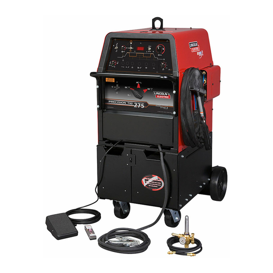
Page 7: Product Description
® PRODUCT DESCRIPTION PRECISION TIG PRODUCT DESCRIPTION The Precision TIG ® 275 is part of a family of industrial arc welding RECOMMENDED EQUIPMENT/INTERFACE power sources providing constant current, single range square wave AC/DC TIG (GTAW) with patented Micro-Start II Technology, TIG (air cooled) Presettable Min. - Page 8 ® PRECISION TIG INSTALLATION TECHNICAL SPECIFICATIONS-Precision TIG ® 275 (K2620-1 Export-50/60Hz) RATED INPUT - SINGLE PHASE ONLY Duty Cycle-Applications Voltage Max. Amps With Out Max. Amps With + 10% Power Factor Capacitor Power Factor Capacitor AC/DC Stick / Balance TIG 95/55/50 80/46/43 Unbalance (70% Penetration...
-
Page 9: Physical Dimensions
® PRECISION TIG INSTALLATION RECOMMENDED INPUT WIRE AND FUSE SIZES For all Stick, DC TIG, and Balanced AC TIG Welding at 275A/40% Duty Cycle with out Standard Power Factor Correction Capacitors Based on the 1999 U.S. National Electrical Code Input Type 75°C Fuse Input... -
Page 10: Installation
® PRECISION TIG INSTALLATION SAFETY PRECAUTIONS ENVIRONMENTAL RATING Read entire installation section before starting Precision TIG ® 275 power sources carry an IP21S Environmental installation. rating. They are rated for use in damp, dirty rain-sheltered envi- ronments. WARNING MACHINE GROUNDING AND HIGH FREQUENCY ELECTRIC SHOCK can kill. -
Page 11: Input And Grounding Connections
® PRECISION TIG INSTALLATION 5. The work terminal must be connected to a ground within ten INPUT and GROUNDING CONNECTIONS feet of the welder, using one of the following methods: WARNING • A metal underground water pipe in direct contact with the ELECTRIC SHOCK can kill. -
Page 12: Output Cable, Connections And Limitations
® PRECISION TIG INSTALLATION 1. Connect the terminal marked (below the reconnect panel) Recommended Cable Sizes for Combined Lengths of Copper to an earth ground. Work and Electrode Cables using 75 C Wire: 2. Connect the input leads to terminals marked L1 (U) and L2 (V) Machine Rating 0 to 100 Ft. -
Page 13: Tig Torch Connection
® PRECISION TIG INSTALLATION FIGURE A.2 TIG TO RCH REM OTE CONNECTIO N CONTROL PAN EL RECEPTAC LE STICK STICK WORK WORK WORK STICK ELE CTRODE STUD STUD (Shown without hinged stud cover) FIGURE A CA BLE STRAIN REL I EF HOLE S CYLINDER could explode TIG TORCH CONNECTION if damaged. -
Page 14: Auxiliary Power Connections
ELECTODE ® PRECISION TIG INSTALLATION AND/OR GAS OUTPUT 5/8-18 RH FIGURE A.3 OUTPUT (front) Panel INPUT (back) Panel Air Cooled Torch Torch Adapter For Gas Supply COOLANT OUT GAS INPUT hose 5/8-18 LH 5/8-18 RH with 5/8 - 18RH Two - Cable K2166-2 (Opt.) Male (PTA-9,-7,-26) -
Page 15: Robotic Interface Connection
® PRECISION TIG INSTALLATION ROBOTIC INTERFACE CONNECTION Robotic interface can be made at the Remote Receptacle (See Operation Section B-2). The machine is shipped with the remote receptacle circuit internally connected to receptacle J5 of the Control board for standard Amptrol operation. In order to enable the remote receptacle for robotic interface its connection plug must be moved from J5 to J5A on the Control board. -
Page 16: Operation
® PRECISION TIG OPERATION SAFETY PRECAUTIONS PIPE THAWING The Precision TIG ® 275 is not recommended for pipe thawing. Read and understand this entire section before operating the machine. Duty Cycle WARNING The duty cycle is based upon a 10-minute time period; i.e., for 40% duty cycle, it is 4 minutes welding and 6 minutes idling. -
Page 17: Controls And Settings
® PRECISION TIG OPERATION CONTROLS AND SETTINGS The Front Control Panel contains the knobs and switches necessary for adjusting the operation of the Precision TIG ® 275, with function indicator lights and an electronic display for volts and amps. The components are described below: FIGURE B.1 - CONTROL PANEL 1. - Page 18 ® PRECISION TIG OPERATION • When the Polarity Switch is set to DC (- or +), the TIG mode provides high frequency only for starting. • With the Current Control switch to REMOTE position, this knob sets the maximum welding level that the Peak output Hi-Freq.
- Page 19 ® PRECISION TIG OPERATION 7a MENU BUTTON AND DISPLAY SWITCH – Pressing and hold- TIG Mode Menu (with Advanced Control Panel installed): ing the (Menu) Button for about 5 seconds enters the menu Setting: Description: display which allows: Selection 4: HS (TIG Hot Start % of output setting) (Only setting for SS0, above.) election of up to seven programmable parameters...
- Page 20 ® PRECISION TIG OPERATION 8. DIGITAL METER AND DISPLAY SWITCH– A (3- digit) LED FIGURE B.2 meter is used to monitor the preset and actual welding proce- REMOTE RECEPTACLE * dure based on the Display (momentary) switch position: (Front View) •...
- Page 21 ® PRECISION TIG OPERATION • In 4-Step position allows welding without continuously holding the 15. PULSE % ON TIME/SPOT TIME CONTROL – This knob sets the start switch trigger. The arc start switch functions in the following time for Pulse or Spot modes: manner: •...
-
Page 22: Internal Set Up Controls
® PRECISION TIG OPERATION INTERNAL SET UP CONTROLS TIG WELDING FEATURES Precision TIG ® 275 models which have an Advanced Panel The following DIP switch feature selections function only when (K2621-1) option installed* have the following additional control the Precision TIG ®... - Page 23 ® PRECISION TIG OPERATION FIGURE B.3 (With DIP Switch #2 OFF) (With DIP Switch #2 ON, As Shipped) FIG. 1...
- Page 24 ® PRECISION TIG OPERATION FIGURE B.4 (With DIP Switch #3 ON) (With DIP Switch #3 OFF, As Shipped) FIG. 2...
-
Page 25: Step Trigger Modes
® PRECISION TIG OPERATION TIG WELD CYCLE CHART SEE ITEM 12 SEE ITEM 12 SEE ITEM 12 SEE ITEM 12 SEE ITEM 7a SEE ITEM 6 SEE ITEM 6 & 7 SEE ITEM 7 SEE ITEM 15 SEE ITEM 14 SEE ITEM 7 SEE ITEM 15 SEE ITEM 7a... -
Page 26: Setup For Tig Amptrol Welding
® PRECISION TIG OPERATION FIGURE B.6 Setup for TIG Amptrol Welding Standard Controls Power Switch Mode Switch Polarity Switch AC Balance AUTO Set: More + for alum.oxide " Cleaning" w/o "Spitting" or " wetting" loss. Balanced for equal + and - current. More - for higher "... -
Page 27: Making A Tig Weld With An Amptrol
® PRECISION TIG OPERATION MAKING A TIG WELD WITH AN AMPTROL Close the arc start switch. This opens the gas valve to auto- matically purge air from the hose and torch, then shields the arc strike area. After the 0.5 second preflow time, the high 1. -
Page 28: Accessories
® PRECISION TIG ACCESSORIES OPTIONAL EQUIPMENT • Magnum ® PTA and PTW Series Torches All Air Cooled or Water-Cooled Magnum ® TIG Torches may be used with the Precision TIG ® 275. Connection adapters are FACTORY INSTALLED OPTIONS only required for Air-Cooled Torches (Refer to Diagrams on A-7) INSTALLATION SECTION: The basic Precision TIG ®... -
Page 29: Maintenance
® PRECISION TIG MAINTENANCE SAFETY PRECAUTIONS OVERLOAD PROTECTION FAN-AS-NEEDED (F.A.N.) WARNING The Precision TIG ® 275 has the F.A.N. circuit feature, which ELECTRIC SHOCK can kill. means the cooling fan will operate only while welding; then for • Only qualified personnel should about 8 minutes after welding has stopped to assure proper perform this maintenance. -
Page 30: Under-Cooler Service
® PRECISION TIG MAINTENANCE SERVICE PROCEDURES FIGURE C.1 SPARK GAP Operation of the Precision TIG ® should be trouble-free for the life of the machine. Should a malfunction occur, however, the follow- ing procedures will be useful to trained service personnel with .015 Spark Gap experience in repairing arc welding equipment: COMPONENT ACCESS... -
Page 31: Meter Calibration Adjustment
® PRECISION TIG MAINTENANCE METER CALIBRATION ADJUSTMENT 3. Using a DC (avg.) test voltmeter with at least 1% accuracy at up to 100 volts, connect it across the WORK (+) and ELECTRODE (-) studs on the front The Precision TIG ®... -
Page 32: Troubleshooting
HOW TO USE TROUBLESHOOTING GUIDE WARNING Service and Repair should only be performed by Lincoln Electric Factory Trained Personnel. Unauthorized repairs per- formed on this equipment may result in danger to the technician and machine operator and will invalidate your factory war- ranty. -
Page 33: Troubleshooting
® PRECISION TIG TROUBLE SHOOTING Observe all Safety Guidelines detailed throughout this manual PROBLEMS POSSIBLE RECOMMENDED (SYMPTOMS) CAUSE COURSE OF ACTION OUTPUT PROBLEMS Thermal light comes on. 1. Thermal shut down. Dirt and dust may have clogged the cooling channels inside machine;... - Page 34 ® PRECISION TIG TROUBLE SHOOTING Observe all Safety Guidelines detailed throughout this manual PROBLEMS POSSIBLE RECOMMENDED (SYMPTOMS) CAUSE COURSE OF ACTION METER PROBLEMS Meter does not light up. 1. Bad meter or its connection. 2. Bad connection at P13 of Control PC board.
- Page 35 ® PRECISION TIG TROUBLE SHOOTING Observe all Safety Guidelines detailed throughout this manual PROBLEMS POSSIBLE RECOMMENDED (SYMPTOMS) CAUSE COURSE OF ACTION HI-FREQ PROBLEMS No hi-freq. 1. Circuit breaker CB1 open. 2. Bad connection at P12 of Control PC board. 3. Spark gaps shorted. 4.
- Page 36 ® PRECISION TIG TROUBLE SHOOTING Observe all Safety Guidelines detailed throughout this manual PROBLEMS POSSIBLE RECOMMENDED (SYMPTOMS) CAUSE COURSE OF ACTION PRESET & OUTPUT CONTROL PROBLEMS Meter does not display preset. 1. Faulty potentiometer R1 or its connection. 2. Bad connection at P9 of Control PC board. 3.
- Page 37 ® PRECISION TIG TROUBLE SHOOTING Observe all Safety Guidelines detailed throughout this manual PROBLEMS POSSIBLE RECOMMENDED (SYMPTOMS) CAUSE COURSE OF ACTION STICK WELDING PROBLEMS Stick electrode "blast off" when arc is 1. Current may be set too high for electrode struck.
- Page 38 ® PRECISION TIG TROUBLE SHOOTING Observe all Safety Guidelines detailed throughout this manual PROBLEMS POSSIBLE RECOMMENDED (SYMPTOMS) CAUSE COURSE OF ACTION TIG PROBLEMS Arc "pulsates" in AC polarity, DC polarity is 1.Micro switch S2A on polarity switch does o.k.. not open in AC polarity. Black area along weld bead.
-
Page 39: Wiring Diagrams
® PRECISION TIG WIRING DIAGRAM... -
Page 40: Dimension Prints
® PRECISION TIG DIMENSION PRINT... -
Page 41: Parts List
P-543 P-543 PARTS LIST FOR Precision TIG 275 & 375 ® Precision TIG ® 275 & 375... - Page 42 P-543-A P-543-A ILLUSTRATION OF SUB-ASSEMBLIES IN G IN G L I N L I N IL E IL E W IT W IT IN G IN G 05-20-2010 Precision TIG ® 275 & 375...
- Page 43 P-543-A.1 P-543-A.1 Precision TIG 275 & 375 ® For Codes: 11160, 11163, 11370 & 11371 Do Not use this Parts List for a machine if its code number is not listed. Contact the Service Department for any code numbers not listed. Use the Illustration of Sub-Assemblies page and the table below to determine which sub assembly page and column the desired part is located on for your particular code machine.
- Page 44 P-543-B.1 P-543-B.1 OPTIONAL EQUIPMENT LISTING Miscellaneous Options Available for your machine are listed below: # Indicates a change this printing. DESCRIPTION ...............PART NUMBER Arc Start Switch .
- Page 45 MISCELLANEOUS ITEMS P-543-B.2 P-543-B.2 (THESE ITEMS ARE NOT ILLUSTRATED) # Indicates a change this printing. Use only the parts marked “x” in the column under the heading number called for in the model index page. 1 2 3 4 5 6 7 8 9 DESCRIPTION PART NO.
- Page 46 P-543-C P-543-C Case Front Assembly 5A 5D Advanced Control Panel 19A 19B 19B 19C W AR W AR NI NG L IN L IN T SW T SW S TI S TI E LE E LE C TR C TR 05-20-2010 Precision TIG ®...
- Page 47 P-543-C.1 P-543-C.1 # Indicates a change this printing. Use only the parts marked “x” in the column under the heading number called for in the model index page. 1 2 3 4 5 6 7 8 9 ITEM DESCRIPTION PART NO. QTY.
- Page 48 P-543-C.2 P-543-C.2 # Indicates a change this printing. Use only the parts marked “x” in the column under the heading number called for in the model index page. 1 2 3 4 5 6 7 8 9 ITEM DESCRIPTION PART NO. QTY.
- Page 49 P-543-C.3 P-543-C.3 # Indicates a change this printing. Use only the parts marked “x” in the column under the heading number called for in the model index page. 1 2 3 4 5 6 7 8 9 ITEM DESCRIPTION PART NO. QTY.
- Page 50 P-543-D P-543-D Arc Starter & Bypass Assembly 05-20-2010 Precision TIG ® 275 & 375...
- Page 51 P-543-D.1 P-543-D.1 # Indicates a change this printing. Use only the parts marked “x” in the column under the heading number called for in the model index page. 1 2 3 4 5 6 7 8 9 ITEM DESCRIPTION PART NO. QTY.
- Page 52 P-543-E P-543-E Case Back Assembly 4C 4D 18B 19 18D 18C 05-20-2010 Precision TIG ® 275 & 375...
- Page 53 P-543-E.1 P-543-E.1 # Indicates a change this printing. Use only the parts marked “x” in the column under the heading number called for in the model index page. 1 2 3 4 5 6 7 8 9 ITEM DESCRIPTION PART NO. QTY.
- Page 54 P-543-E.2 P-543-E.2 # Indicates a change this printing. Use only the parts marked “x” in the column under the heading number called for in the model index page. 1 2 3 4 5 6 7 8 9 ITEM DESCRIPTION PART NO. QTY.
- Page 55 NOTES Precision TIG ® 275 & 375...
- Page 56 P-543-F P-543-F Center Assembly 19B19C 19C19D 05-20-2010 Precision TIG ® 275 & 375...
- Page 57 P-543-F.1 P-543-F.1 # Indicates a change this printing. Use only the parts marked “x” in the column under the heading number called for in the model index page. 1 2 3 4 5 6 7 8 9 ITEM DESCRIPTION PART NO. QTY.
- Page 58 P-543-F.2 P-543-F.2 # Indicates a change this printing. Use only the parts marked “x” in the column under the heading number called for in the model index page. 1 2 3 4 5 6 7 8 9 ITEM DESCRIPTION PART NO. QTY.
- Page 59 P-543-F.3 P-543-F.3 # Indicates a change this printing. Use only the parts marked “x” in the column under the heading number called for in the model index page. 1 2 3 4 5 6 7 8 9 ITEM DESCRIPTION PART NO. QTY.
- Page 60 P-543-G P-543-G Cover Assembly 05-20-2010 Precision TIG ® 275 & 375...
- Page 61 P-543-G.1 P-543-G.1 # Indicates a change this printing. Use only the parts marked “x” in the column under the heading number called for in the model index page. 1 2 3 4 5 6 7 8 9 ITEM DESCRIPTION PART NO. QTY.
- Page 62 NOTES Precision TIG ® 275 & 375...
- Page 63 NOTES...
- Page 64 Lincoln Electric for advice or information about their use of our products. We respond to our customers based on the best information in our possession at that time. Lincoln Electric is not in a position to warrant or guarantee such advice, and assumes no liability, with respect to such information or advice.