Lincoln Electric PRECISION TIG 375 Operator's Manual
Lincoln electric welder user manual
Hide thumbs
Also See for PRECISION TIG 375:
- Service manual (143 pages) ,
- Operator's manual (68 pages) ,
- Specification sheet (168 pages)
Table of Contents
Advertisement
For use with machines having Code Numbers:
Safety Depends on You
Lincoln arc welding and cutting
equipment is designed and built
with safety in mind. However, your
overall safety can be increased by
proper installation ... and thoughtful
operation on your part. DO NOT
INSTALL, OPERATE OR REPAIR
THIS
EQUIPMENT
WITHOUT
READING THIS MANUAL AND
THE SAFETY PRECAUTIONS
CONTAINED
THROUGHOUT.
And, most importantly, think before
you act and be careful.
• Sales and Service through Subsidiaries and Distributors Worldwide •
Cleveland, Ohio 44117-1199 U.S.A. TEL: 216.481.8100 FAX: 216.486.1751 WEB SITE: www.lincolnelectric.com
RETURN TO MAIN MENU
PRECISION TIG 375
11161, 11162
IP21S
OPERATORʼS MANUAL
• World's Leader in Welding and Cutting Products •
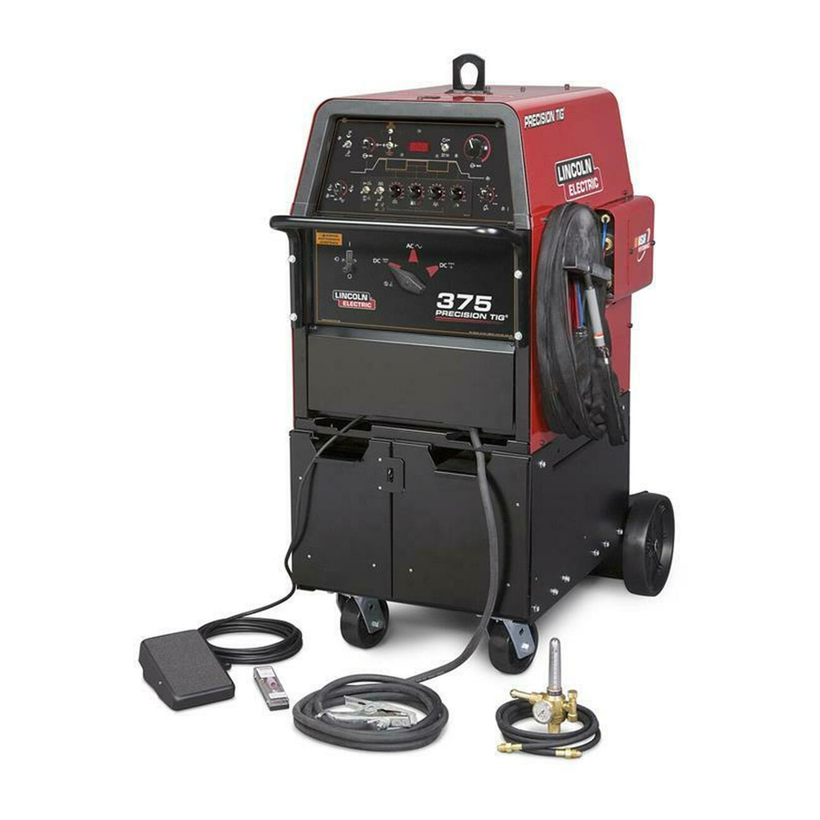
Precision TIG 375 Welding
Package shown with optional
Advanced Control Panel
Copyright © Lincoln Global Inc.
IM898
March, 2008
Advertisement
Table of Contents

Related Manuals for Lincoln Electric PRECISION TIG 375


Summary of Contents for Lincoln Electric PRECISION TIG 375
- Page 1 • Sales and Service through Subsidiaries and Distributors Worldwide • Cleveland, Ohio 44117-1199 U.S.A. TEL: 216.481.8100 FAX: 216.486.1751 WEB SITE: www.lincolnelectric.com RETURN TO MAIN MENU 11161, 11162 Precision TIG 375 Welding Package shown with optional Advanced Control Panel IP21S Copyright © Lincoln Global Inc.
-
Page 2: California Proposition 65 Warnings
Miami, Florida 33135 or CSA Standard W117.2-1974. A Free copy of “Arc Welding Safety” booklet E205 is available from the Lincoln Electric Company, 22801 St. Clair Avenue, Cleveland, Ohio 44117-1199. BE SURE THAT ALL INSTALLATION, OPERATION, MAINTENANCE AND REPAIR PROCEDURES ARE PERFORMED ONLY BY QUALIFIED INDIVIDUALS. -
Page 3: Electric Shock Can Kill
ELECTRIC SHOCK can kill. 3.a. The electrode and work (or ground) circuits are electrically “hot” when the welder is on. Do not touch these “hot” parts with your bare skin or wet clothing. Wear dry, hole-free gloves to insulate hands. - Page 4 WELDING and CUTTING SPARKS can cause fire or explosion. 6.a. Remove fire hazards from the welding area. If this is not possible, cover them to prevent the welding sparks from starting a fire. Remember that welding materials from welding can easily go through small cracks and openings to adjacent areas.
- Page 5 PRÉCAUTIONS DE SÛRETÉ Pour votre propre protection lire et observer toutes les instructions et les précautions de sûreté specifiques qui parraissent dans ce manuel aussi bien que les précautions de sûreté générales suiv- antes: Sûreté Pour Soudage A LʼArc 1. Protegez-vous contre la secousse électrique: a.
- Page 6 We respond to our customers based on the best information in our possession at that time. Lincoln Electric is not in a position to warrant or guarantee such advice, and assumes no liability, with respect to such information or advice.
-
Page 7: Table Of Contents
Installation ...Section A Technical Specifications ...A-1,A-2 Safety Precautions ..Select Suitable Location ...A-3 Grinding ...A-3 Stacking ...A-3 Undercarriage Lifting and Moving ...A-3 Tilting ...A-3 Environmental Rating ...A-3 Machine Grounding and High Frequency Interference Protection ...A-3, A-4 Input and Grounding Connections ...A-4 Output Cable, Connections and Limitations ...A-5 Work Cable Connection ...A-5 Stick Electrode Cable Connection ...A-5... - Page 8 TECHNICAL SPECIFICATIONS-PRECISION TIG 375 (K2624-1 Domestic Package*-60Hz) (K2622-1 Domestic,K2622-2 Canadian-60Hz) RATED INPUT - SINGLE PHASE ONLY Duty Cycle-Applications Number AC/DC Stick / Balance TIG Unbalance (70% Penetration K2622-1 AC/DC Stick / Balance TIG K2624-1 Unbalance (70% Penetration 100% AC/DC Stick / Balance TIG...
-
Page 9: Installation
28.0 in. 41.0 in. 711 mm 1041 mm TEMPERATURE RANGES STORAGE TEMPERATURE RANGE -40°C to +85°C (-40° to +185°F) 180°C (H) PRECISION TIG 375 Auxiliary Power Receptacle for up to: Type 75°C Type 75°C Copper Wire in Input Copper Conduit AWG... -
Page 10: Safety Precautions
• Always connect the Precision TIG 375 to a power supply grounded in accordance with the National Electrical Code and all local codes. -
Page 11: Input And Grounding Connections
4. Keep the torch in good repair and all connections tight to reduce high frequency leakage. 5. The work terminal must be connected to a ground within ten feet of the welder, using one of the fol- lowing methods: • A metal underground water pipe in direct contact with the earth for ten feet or more. -
Page 12: Output Cable, Connections And Limitations
Otherwise, it is user provided. With power source off, connect a separate work cable to the 1/2-13 threaded "WORK" stud of the welder, and secure a tight connection with the flange nut provided. The work cable should be routed through the cable strain relief hole provided in the base directly below the welding output terminal. -
Page 13: Tig Torch Connection
K2166-2 1/2” Stud Connector with with a 7/8-14 LH male fitting. Magnum PTW-18/-20 (or LW-) water-cooled Torches require no adapter for Precision TIG connection. PRECISION TIG 375 TIG TORCH CONNECTION P ANEL WORK... -
Page 14: Auxiliary Power Connections
Cooler or Under-Storage unit, the Foot Pedal (or other remote control accessory) and coiled control cable, or excess cable length, may be conveniently stored in the drawer while remaining connected. PRECISION TIG 375 For Gas Supply hose with 5/8-18RH male (Provided with Weld... -
Page 15: Robotic Interface Connection
0.2A rated switch circuit between pin 1 (+) and pin 2 (com) for an external 40VDC supplied relay (with coil diode). This switch closes when the Peak Pulse is on, and opens when off. PRECISION TIG 375... -
Page 16: Peration
Observe additional Safety Guidelines detailed in the beginning of this manual. OPERATION PRODUCT DESCRIPTION The Precision TIG 375 is part of a new family of indus- trial arc welding power sources providing constant cur- rent, single range square wave AC/DC TIG (GTAW) with patented Micro-Start Min. -
Page 17: Recommended Processes And Equipment
RECOMMENDED PROCESSES AND EQUIPMENT RECOMMENDED PROCESSES The Precision TIG 375 is recommended for the TIG (GTAW) and Stick (SMAW) welding processes within its output capacity range of 2 amps DC, or 5 amps AC, to 420 amps AC/DC. It is compatible with most... -
Page 18: Controls And Settings
* Arc voltage and current are sensed to determine if the arc is established or out. PRECISION TIG 375 1. POWER SWITCH 2. POLARITY SWITCH 3. MODE SWITCH 4. - Page 19 • In STICK mode the Start control is not functional since Hot Start level is fixed, or internal Advanced Panel adjustable (see Section B-7). Pressing the Display (momentary) switch toggle left to Minimum Output position displays minimum amps rating of the machine. PRECISION TIG 375 Technology minimum current...
- Page 20 * Default Factory Setting. (Indicated by "blinking" decimal point.) ◊ Without Factory installed Advanced Control Panel the Stick menu displays “- - -“. PRECISION TIG 375 (Only setting for SS0, above.) (Only setting for SS1 & SS2, above.) ◊ ("Softer" arc)
- Page 21 (LECO S12020-27) ADVANCED PANEL CONTROLS The following Advanced Control Panel controls are standard on the Precision TIG 375: (Refer to Section B-10 Tig Weld Cycle Chart for graphic illustration of these TIG welding functions.) 12. TRIGGER SWITCH – This 2-position switch selects how the arc start switch ( connected to the above Remote receptacle) functions;...
- Page 22 TIG arc starting with minimized Radio Frequency Interference (RFI). Control knob is located on a recessed panel near the easy acces- sible spark gap side panel. As shipped, the control is set to minimum. PRECISION TIG 375...
-
Page 23: Internal Set Up Controls
INTERNAL SET UP CONTROLS Precision TIG 375 Advanced Panel has the following additional control features which are set up using the DIP Switch (S1) provided on the internal panel of this option. Access to this internal panel is obtained by removing... - Page 24 OPERATION FIGURE B.3 (With DIP Switch #2 OFF) (With DIP Switch #2 ON, As Shipped) PRECISION TIG 375...
- Page 25 B-10 B-10 OPERATION FIGURE B.4 (With DIP Switch #3 ON) (With DIP Switch #3 OFF, As Shipped) PRECISION TIG 375...
-
Page 26: Setup Guidelines For Tig Welding With An Amptrol
SEE ITEM 15 SEE ITEM 14 SEE ITEM 15 SEE ITEM 16 SEE ITEM 17 Technology, some tungstens may be PRECISION TIG 375 B-11 SEE ITEM 12 SEE ITEM 7 SEE ITEM 9 SEE ITEM 12 & TIG Welding Features... - Page 27 FIGURE B.6 Setup for TIG Amptrol Welding AC Balance Set: Pulse Frequency 4-6 pps % On Time 40-60% Background Current 40-60% Min.Output PRECISION TIG 375 B-12 Standard Controls Power Switch Mode Switch Polarity Switch Local/Remote Switch Maximum Output Minimum Output Postflow...
-
Page 28: Making A Tig Weld With An Amptrol
Blue Max Stainless Red Baron Stainless Mild steel procedures are based on recommended procedures listed in C2.10 8/94 and the maximum rating of the Precision TIG 375 Excaliber 7018 procedures are based on Jet-LH 78 MR Blue Max procedures are based on C6.1 6/95... -
Page 29: Accessories
See below for more detailed descriptions. FIELD INSTALLED OPTIONS The following Options/Accessories are available for the Precision TIG 375 and are installed per instructions in this manual and / or provided in the package: • K1828-1 Under-Cooler Cart Includes a "cooler-in-a-drawer" with hoses and a lockable storage drawer on a dual bottle undercar- riage (see below). - Page 32 Step 1. LOCATE PROBLEM (SYMPTOM). Step 2. POSSIBLE CAUSE. Step 3. RECOMMENDED COURSE OF ACTION...
- Page 43 ● ● ● ● ● ● ● ● ● ● ● ● ● ● ● ● ● ● ● ●...
- Page 44 ● ● ● ● ● ● ● ● ● ● ● ● ● ● ● ● ● ● ● ● ● ● ●...