Table of Contents
Advertisement
Quick Links
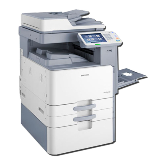
1. Print / Copy speed
• SCX-8030ND : 30 ppm (A4)
• SCX-8040ND : 40 ppm (A4)
2. 800 MHz CPU
3. 250GB HDD
4. 512 MB Memory (Max. 1GB)
Service Manual
Digital Laser MFP
SCX-8030ND / 8040ND series
5. 8.9 inch color graphic touch-screen LCD
6. Various option units
• 3K Booklet fi nisher, 1K Standard fi nisher
DCF, HCF, Punch unit , Multi fax etc.
Advertisement
Table of Contents

Related Manuals for Samsung SCX-8030ND Series


Summary of Contents for Samsung SCX-8030ND Series
-
Page 1: Service Manual
Service Manual Digital Laser MFP SCX-8030ND / 8040ND series 1. Print / Copy speed 5. 8.9 inch color graphic touch-screen LCD • SCX-8030ND : 30 ppm (A4) • SCX-8040ND : 40 ppm (A4) 6. Various option units • 3K Booklet fi nisher, 1K Standard fi nisher 2. - Page 2 GSPN (Global Service Partner Network) Area Web Site Europe,MENA, CIS, https://gspn1.samsungcsportal.com Africa E.Asia, W.Asia, https://gspn2.samsungcsportal.com China, Japan N.America, ⓒ Samsung Electronics Co.,Ltd. August. 2010 https://gspn3.samsungcsportal.com S.America Printed in Korea. VERSION NO. : 0.04 CODE : 80x0-00000E...
-
Page 3: Table Of Contents
Contents chapter 1 Precautions 1.1 Safety Warning …………………………………………………… 1-1 1.2 Caution for safety ………………………………………………… 1-2 1.3 ESD Precautions ………………………………………………… 1-5 chapter 2 Product decription 2.1 Specifi cations …………………………………………………… 2-1 2.2 System confi guration …………………………………………… 2-7 2.3 Sensor location …………………………………………………… 2-16 2.4 Paper handling section …………………………………………... - Page 4 Contents 2.8.1 Drive Motors ………………………………………………… 2-41 2.8.2 Main drive unit (OPC, DEVE, MP, REGI, DUPLEX) …… 2-43 2.8.3 Pick-up Drive ………………………………………………… 2-44 2.8.4 Fuser /Exit Drive …………………………………………… 2-45 2.8.5 Toner Duct Drive …………………………………………… 2-46 2.8.6 Drive of Toner Supply ……………………………………… 2-46 2.8.7 WTB leveling drive …………………………………………...
- Page 5 Contents 2.11.19 Fuser PBA ………………………………………………… 2-87 2.11.20 Waste Sensor PBA ……………………………………… 2-88 2.11.21 LED Panel PBA …………………………………………… 2-88 2.11.22 Scan Joint PBA …………………………………………… 2-89 2.11.23 CCDM PBA ……………………………………………… 2-90 2.11.24 Scan Cover Open Sensor PBA ………………………… 2-91 2.11.25 DADF Length Sensor PBA ……………………………… 2-91 2.11.26 DADF Width Sensor PBA ………………………………...
- Page 6 Contents 3.4.10 Home sensor ……………………………………………… 3-18 3.4.11 Scanner heating cable …………………………………… 3-19 3.4.12 Align set …………………………………………………… 3-23 3.5 Fuser unit ………………………………………………………… 3-24 3.6 Side Unit …………………………………………………………… 3-35 3.6.1 Duplex sensors ……………………………………………… 3-36 3.7.2 Transfer sensors …………………………………………… 3-37 3.7.3 MP unit ……………………………………………………… 3-39 3.7 Electrical components ……………………………………………...
- Page 7 Contents 3.15 Frame Duct …………………………………………………… 3-74 3.16 DADF Unit ……………………………………………………… 3-75 3.16.1 Width / Length sensor PBA ……………………………… 3-84 3.16.2 DADF Main PBA …………………………………………… 3-85 3.16.3 DADF Motors ……………………………………………… 3-87 3.16.4 DADF cover open sensor ………………………………… 3-90 3.16.5 Pick-Up Guide Sensor PBA ……………………………… 3-91 3.16.6 DADF Solenoid ……………………………………………...
- Page 8 Contents 4.5.1 Engine diagnostics ………………………………………… 4-13 4.5.1.1 NVM Read/Write ……………………………………… 4-13 4.5.1.2 Engine Test Routines ………………………………… 4-13 4.5.2 Fax diagnostics …………………………………………… 4-14 4.5.2.1 Fax NVM Read/Write ………………………………… 4-14 4.5.2.2 Fax Test Routines ……………………………………… 4-15 4.5.3 Scanner diagnostics ……………………………………… 4-17 4.5.3.1 Shading Test …………………………………………...
- Page 9 Contents chapter 6 Preventive Maintenance (PM) 6.1 PM Supplies ……………………………………………………… 6-1 6.2. PM Procedures ………………………………………………… 6-5 6.2.1 Toner cartridge ……………………………………………… 6-5 6.2.2 Imaging unit ………………………………………………… 6-7 6.2.3 2nd Transfer roller ………………………………………… 6-11 6.2.4 Fuser Unit …………………………………………………… 6-12 6.2.5 Pick up/ Retard/ Forward roller …………………………… 6-13 6.2.6 Ozone Filter …………………………………………………...
- Page 10 Contents 7.3.6 Uneven pitch and jitter image ……………………………… 7-107 7.3.7 Skewed image ……………………………………………… 7-108 7.3.8 Low image density ………………………………………… 7-109 7.3.9 Blank copy, Black copys …………………………………… 7-110 7.3.10 Uneven density in sub scan direction …………………… 7-112 7.3.11 Uneven density in main scan direction ………………… 7-113 7.3.12 Poor fusing performance …………………………………...
- Page 11 Contents Reference Information chapter 10 10.1 Tools for troubleshooting ……………………………………… 10-1 10.2 Abbreviations …………………………………………………… 10-4...
-
Page 12: Safety Warning
High voltages and lasers inside this product are da ngerous. This printer should only be serviced by a qualified service technician. (2) Use only Samsung replacement parts (2) Use only Samsung replacement parts. There are no user serviceable parts inside the print ter. -
Page 13: Caution For Safety
(12) Do not insert any metal objects into the machine th hrough the ventilator fan or other part of the casing, it could make contact with a high voltage conductor inside the machine and cause an electric shock. Service Manual SAMSUNG ELECTRONICS SCX-8030/8040 series Version 0.05... -
Page 14: Handling Precautions
OPC-ACR surely. 1.2.4 Assembly / Disassembly Precau utions Replace parts carefully and always use Samsung part ts. Take care to note the exact location of parts and cable routing before dismantling any part of the machi ne. - Page 15 - If you are moving the machine a long distance, you s should remove toner & imaging unit, lock scan carrier & staple unit, tape and disassemble all trays. (e.g : mo oved by truck or so) Service Manual SAMSUNG ELECTRONICS SCX-8030/8040 series Version 0.05...
-
Page 16: Esd Precautions
ESDs. Normal motions, such as the brushing together of clothing fabric and lifting on ne’s foot from a carpeted floor, can generate static electricity sufficient to damage an ESD electricity sufficient to damage an ESD. Service Manual SAMSUNG ELECTRONICS SCX-8030/8040 series Version 0.05... -
Page 17: Product Description
Note - See the Rating label on the machine for correct voltage, frequency (hertz) wire in DCF/HCF and type of current. The voltage rating of h heating wire is the same as the machine’s voltage rating. Service Manual SAMSUNG ELECTRONICS SCX-8030/8040 series Version 0.05... -
Page 18: Printer Specifications
• Platen : 600 x 600 dpi Copy resolution • Document feeder: Up to 60 00 x 600 dpi • Platen : 25% to 400% Zoom range Zoom range • Document feeder: 25% to 4 400% Service Manual SAMSUNG ELECTRONICS SCX-8030/8040 series Version 0.05... -
Page 19: Scanner Specifications
03 x 196 dpi Resolution • Super F Fine : 300 x 300 dpi • Ultra Fin ne : 600 x 600 dpi Memory HDD Bac ckup Auto dialer up to 500 numbers Service Manual SAMSUNG ELECTRONICS SCX-8030/8040 series Version 0.05... -
Page 20: Paper Specifications
Imaging unit MLT-R607K 100K pa ages Waste Toner Container MLT-W606 300K pa ages * American 35K Toner can be used for SCX-8030ND ** Declared yield value in accordance with 6% covera age. Service Manual SAMSUNG ELECTRONICS SCX-8030/8040 series Version 0.05... - Page 21 Heating wire for Scan 220V V, 5W and 10W (equipped by service person at field, CLX-DHK12S volta age rating of Heating Wire is the same as the machine’s volta age rating) Service Manual SAMSUNG ELECTRONICS SCX-8030/8040 series Version 0.05...
- Page 22 (CLX-D DSK10T) DSK10T) (CLX PFP000) (CLX-PFP000) (CLX HCF102) (CLX-HCF102) Expansion memory module 512M Expansion memory module 512M D I kit D I kit (SCX-MEM300) (CLX X-KIT10F) Cassette / Scanner Heating cable (CLX-DHK11C/12C/11S/12S) Service Manual SAMSUNG ELECTRONICS SCX-8030/8040 series Version 0.05...
-
Page 23: System Confi Guration
DADF width guides Standard tray (tray1, tray2) DADF input tray Front door DADF output tray Front door handle Standard tray right bottom door Control panel DCF right bottom door Center tray * Optional device Service Manual SAMSUNG ELECTRONICS SCX-8030/8040 series Version 0.05... -
Page 24: Front View 2
2. Product D Description Front view 2 Scanner glass Power-switch it h White sheet Power receptacle Multi-purpose tray USB port (2 EA) Multi-purpose tray width guide Job separator* * Optional device Service Manual SAMSUNG ELECTRONICS SCX-8030/8040 series Version 0.05... - Page 25 2. Product D Description Rear view DCF cable DCF cable USB host port USB host port DADF cable Finisher connector Scanner locking screw Network port USB port (Connection port to compu uter) Service Manual SAMSUNG ELECTRONICS SCX-8030/8040 series Version 0.05...
-
Page 26: Inner View
Locking lever NOTE If you want to see the imaging unit, you need to o remove the waste toner container. Lift the locking lever upward. Then remove the waste toner con ntainer. Service Manual SAMSUNG ELECTRONICS SCX-8030/8040 series Version 0.05... - Page 27 2. Product D Description View with standard finisher (option Standard finisher front door Top tray Manual stapler Top door Manual stapler button Standard finisher Front door handle Finishing tray Staple Service Manual SAMSUNG ELECTRONICS SCX-8030/8040 series Version 0.05...
- Page 28 2. Product D Description View with booklet finisher1 (optiona Booklet tray Manual stapler button Finishing tray Top tray Booklet finisher front door Top door Manual stapler Booklet finisher front door handle Service Manual SAMSUNG ELECTRONICS SCX-8030/8040 series Version 0.05...
- Page 29 Booklet Staple (2 EA) Fold wheel Booklet maker cover Booklet jam removal wheel Note If you want to open the booklet maker, hold the bo ooklet maker handle and pull it out. Service Manual SAMSUNG ELECTRONICS SCX-8030/8040 series Version 0.05...
- Page 30 Face down output tray Optional tray Document output tray (Stand / HCF / DCF) Toner cartridges Pick up r rollers Document input tray Laser scanning unit MP tray Imaging units Transfer roller unit Service Manual SAMSUNG ELECTRONICS SCX-8030/8040 series Version 0.05...
-
Page 31: Paper Path
2. Product D Description Paper Path The following diagram displays the path the paper follo ows during the printing process. DADF path Finisher path Duplex path Simplex path Service Manual SAMSUNG ELECTRONICS SCX-8030/8040 series Version 0.05... -
Page 32: Sensor Location
JC92 02302A PHOTO-INTERRUPTER 0604-00 01393 M1-4211 SCX-8040ND PHOTO-INTERRUPTER 0604-00 01393 M1-4211 : JC92-02221A PHOTO-INTERRUPTER 0604-00 01393 C7-1311 SENSOR-PAPER SIZE JC32-00 0013A M1-4111 SENSOR-PAPER SIZE JC32-00 0013A M1-4211 SENSOR-HUMIDITY JC32-00 0005A A3-3311 / A3-3312 Service Manual SAMSUNG ELECTRONICS SCX-8030/8040 series Version 0.05... - Page 33 Description Description Controller PCB Controller PCB Relative Error Code Relative Error Code Number PBA-ENGINE JC32-00010 C3-5212 Charger Clean SNR SCX-8030ND : JC92-02302A Toner SNR 3405-00109 C3-5422 SCX-8040ND : JC92 02221A : JC92-02221A Service Manual SAMSUNG ELECTRONICS SCX-8030/8040 series Version 0.05...
- Page 34 M3-1213 M3-1214 PHOTO-INTERRUPTER 0604-00139 M3-2430 M3-1411 PBA ENGINE PBA-ENGINE PHOTO INTERRUPTER PHOTO-INTERRUPTER 0604 00139 0604-00139 M3 1413 M3-1413 (JC92-02221A) M3-1414 M2-2411 PHOTO-INTERRUPTER 0604-00138 M2-2413 M2-2414 M2-1331 PHOTO-INTERRUPTER 0604-00139 M2-1333 M2 1334 M2-1334 Service Manual SAMSUNG ELECTRONICS SCX-8030/8040 series Version 0.05...
- Page 35 M2-1121 M1 1113 M1-1113 PHOTO-INTERRUPTER 0604-00 01393 M1-5112 PHOTO-INTERRUPTER 0604-00 01393 M1-4111 PHOTO-INTERRUPTER 0604-00 01393 S2-4A10 M1-1213 M2-1134 PHOTO-INTERRUPTER 0604-00 01381 M2-1135 M2-1131 M1-1213 PHOTO-INTERRUPTER 0604-00 01393 M1-5212 PHOTO-INTERRUPTER 0604-00 01393 M1-4211 Service Manual SAMSUNG ELECTRONICS SCX-8030/8040 series Version 0.05...
-
Page 36: Paper Handling Section
2.4.1 Overview The following diagrams display the positions of the pa per path rollers. EXIT (OPTION) EXIT SIDE TAKEAWAY CASSETTE DUPLEX DUPLEX REGI PICKUP Service Manual SAMSUNG ELECTRONICS SCX-8030/8040 series Version 0.05... - Page 37 Pick Up size detection Tray1 transport detection Tray2 paper empty detection Tray2 lift Tray2 transport detection motor Tray2 paper size detection Tray2 upper limit detection Tray2 pape er remaining quantity det tection Service Manual SAMSUNG ELECTRONICS SCX-8030/8040 series Version 0.05...
- Page 38 MP media size detection Detects MPF paper s size CN7 @ SIDE JOINT PBA, 3Pin (Long media) MPF Paper empty detection Detects MPF paper e empty CN2 @ SIDE JOINT PBA, 3Pin Service Manual SAMSUNG ELECTRONICS SCX-8030/8040 series Version 0.05...
-
Page 39: Components
Roller fuser Sensor fuser out Roller exit Roller face down exit Actuator face down bin f ll full Sensor duplex return Roller duplex return Roller 2nd exit Actuator 2nd Exit bin full Service Manual SAMSUNG ELECTRONICS SCX-8030/8040 series Version 0.05... -
Page 40: Functions
Registration Sensor This sensor detects that the leading edge of the paper r has reached the registration roller and that the trailing edge of the paper has passed the registration r roller. Service Manual SAMSUNG ELECTRONICS SCX-8030/8040 series Version 0.05... -
Page 41: Paper Tray
-. Special Paper : 12"×18", Label (Label : 50 shee ets) • Weight : plain paper 60 ~ 163 g/㎡ • Plate knock up Lift type : Lift Motor + Up Limit Senso Service Manual SAMSUNG ELECTRONICS SCX-8030/8040 series Version 0.05... -
Page 42: Pick Up Unit
The following is a diagram of the pickup roller: Forward Roller Retard Roller Actuator-Empty Sensor Pick Up Roller Service Manual SAMSUNG ELECTRONICS SCX-8030/8040 series Version 0.05... -
Page 43: Registration Unit
-. Duplex Top Margin : 4.23 ± 2.5 mm ( Tray3 , 4, HCF : 4.23 ± 3.0 mm ) -. Duplex Side Margin : 3 ± 2.5 mm ( Tray3, 4 , HCF : 3 ± 3.0 mm ) Service Manual SAMSUNG ELECTRONICS SCX-8030/8040 series Version 0.05... -
Page 44: Mpf Unit
This machine uses an FRR (Feed and Reverse Roller) system for feeding paper. There is friction between the feed roller [E] and Retard roller [D]. This friction separates the top sheet of paper from the stack. Service Manual SAMSUNG ELECTRONICS SCX-8030/8040 series Version 0.05... -
Page 45: Printing Process Overview
6. Quenching for OPC drum: Quenching is done by illuminating the whole area of the drum with the LED lamps at the end of every job. Service Manual SAMSUNG ELECTRONICS SCX-8030/8040 series Version 0.05... -
Page 46: Imaging Unit
The CRUM chip in the image unit stores the data abou ut the Imaging unit. Light guide Cleaning blade Scorotron Scorotron OPC Drum Magnetic Roller Mixing Auger Service Manual SAMSUNG ELECTRONICS SCX-8030/8040 series Version 0.05... -
Page 47: Drum Drive
OPC and Mag Roller is driven by a motor. The OPC D Drum and Mag roller are supplied with power from the coupling. Drive transmission gear Drive motor BLDC Coupling Drum-K BLDC motor Gear-Drive OPC Coupling OPC Coupling Deve Service Manual SAMSUNG ELECTRONICS SCX-8030/8040 series Version 0.05... - Page 48 Th e imaging unit is equipped with a CRUM in which some information about the imaging unit is stored. [A] Magnetic Roller Mixing Auger [C] TC Sensor [B] Mixing Auger Service Manual SAMSUNG ELECTRONICS SCX-8030/8040 series Version 0.05...
- Page 49 Filters [B] on the top of the development unit ensure tha at the internal pressure does not become too high. During the operating , this prevents contamination of th he imaging unit by the toner. [B] Filte [A] Auger Service Manual SAMSUNG ELECTRONICS SCX-8030/8040 series Version 0.05...
-
Page 50: Fuser Unit
Thermistor um-Fuser Belt Center : 0.5mm-1.0mm distance Side : Contact Thermostat NC Sensor Pressure Roller Halogen L Halogen L Lamp Lamp Service Manual SAMSUNG ELECTRONICS SCX-8030/8040 series Version 0.05... -
Page 51: Fuser Unit Components
NC sensor malfunction. These thermostats are used to prevent abnormal ope eration. When the thermostat is triggered, it must be replaced (as well as the other damaged parts in the f fuser unit). Service Manual SAMSUNG ELECTRONICS SCX-8030/8040 series Version 0.05... -
Page 52: Fuser Unit Drive
The fusing/paper exit motor [A] drives the pressure rolle er [B] through the gear train. The fuser belt [C] is driven by pressure with the pressure roller [B]. ith th Exit Motor [A] Fuser Belt [C] Pressure Roller [B] Service Manual SAMSUNG ELECTRONICS SCX-8030/8040 series Version 0.05... -
Page 53: Temperature Control
170°C, it opens and cuts power to the fusing lamp. If the other thermostat temperature becomes h higher than 170°C, it also opens and cuts power to the fusing lamp. Service Manual SAMSUNG ELECTRONICS SCX-8030/8040 series Version 0.05... -
Page 54: Laser Scanning Unit
LSU from the contamination. For interface with set, LSU has the LD PBA on front side. Scan direction Information Part Code : JC97-03700A [LSU] LD PBA P/Mirror Motor P/Mirror Motor F1 Lens F2 Lens Cover glass Service Manual SAMSUNG ELECTRONICS SCX-8030/8040 series Version 0.05... - Page 55 : 40/30 ppm common use P/Motor 22,677 rpm 16,299 rpm speed Process 192 mm/sec 138 mm/sec Speed Harness : 22 Pin Harness : 22 Pin interface (Interface with set ) (Interface with set ) Service Manual SAMSUNG ELECTRONICS SCX-8030/8040 series Version 0.05...
-
Page 56: Laser Synchronizing Detectors
Main Scan Start Detection A beam is detected by the BD PBA at the scanning sta art point and creates the horizontal sync signal (Hsync). The picture below shows the data scanning direction. Service Manual SAMSUNG ELECTRONICS SCX-8030/8040 series Version 0.05... -
Page 57: Printer Drive System
The following table list the descriptions for the tagged drive locations. Related ITEM Type Function error Duplex Return HB-STEP Duplex return driving BLDC Fuser/Exit driving Fuser/Exit E CLT E-CLT E it d i i Exit driving Service Manual SAMSUNG ELECTRONICS SCX-8030/8040 series Version 0.05... - Page 58 MP / Regi / Duplex control OPC / DEVE BLDC OPC/DEVE PR Release PM-STEP PR Release driving PM-STEP PM-STEP Waste Tank leveling Waste Tank leveling CST Lift 1st , 2nd CST Lift Service Manual SAMSUNG ELECTRONICS SCX-8030/8040 series Version 0.05...
-
Page 59: Main Drive Unit (Opc, Deve, Mp, Regi, Duplex)
BLDC (MP/REGI/DUP) (MP/REGI/DUP) BLDC (OPC/Dev) Regi Control Clutch Rear View OPC Coupling Deve (Auger) Duplex Drive Gear Coupling REGI Drive Gear MP Drive Gear Information Part Code : JC93-00118A [DRIVE MAIN] Service Manual SAMSUNG ELECTRONICS SCX-8030/8040 series Version 0.05... -
Page 60: Pick-Up Drive
H-Step Pulley Gear Pulley Gear Gear Gear Clutch Clutch Pick-up 1 driving Pick up 1 driving Belt Belt Gear Feed 1 driving Feed 2 driving Gear Gear Gear E-Clutch Pick-up 2 driving Service Manual SAMSUNG ELECTRONICS SCX-8030/8040 series Version 0.05... -
Page 61: Fuser/Exit Drive
-Duplex Return : HB-Step is interlocked. 1. BLDC FUSER A/B Fuser Roll driving EXIT RDCN EXIT IDLE A EXIT IDLE B Clutch-E Exit Roll driving Duplex Re eturn driving 2. H-Step DUP RDCN Service Manual SAMSUNG ELECTRONICS SCX-8030/8040 series Version 0.05... -
Page 62: Toner Duct Drive
GEAR DUCT RDCN Toner Du uct Driving 2.8.6 Drive of Toner Supply The following photo displays the location of the Toner Supply drive: Bottle Coupling Information Part Code : JC31-00124A [MOTOR GEARED-T_SUPPLY] Service Manual SAMSUNG ELECTRONICS SCX-8030/8040 series Version 0.05... -
Page 63: Wtb Leveling Drive
PM Step motor & Worm : PR R Release Driving GEAR PR GEAR PR RDCN RDCN Step (PM) Step (PM) GEAR WORM WHEEL GEAR WORM WHEEL PR Release Driving PR Release Driving GEAR ENCODER GEAR ENCODER Service Manual SAMSUNG ELECTRONICS SCX-8030/8040 series Version 0.05... -
Page 64: Scanner System
7. Auto Paper Sensor Reflector 2. FR module 3. HR module 1. DADF Glass Xe-Lamp 6. Scan Main Board 5. CCD Board 4. Lens Driving Pulley Service Manual SAMSUNG ELECTRONICS SCX-8030/8040 series Version 0.05... - Page 65 This is a plate to efficiently direct the light from the e Xe-lamp to the surface of the Document on the glass. • • Mirror 1 Mirror-1 This mirror directs the light reflected from the Doc ument to the mirror-2 (described later). Service Manual SAMSUNG ELECTRONICS SCX-8030/8040 series Version 0.05...
- Page 66 This is a board to perform image correction, such as shading correction and Image Enhancement. 7. Auto Paper Sensor The size of an original placed on the glass is instantly y detected using the Auto Paper Sensor fixed on the Align-frame. Service Manual SAMSUNG ELECTRONICS SCX-8030/8040 series Version 0.05...
-
Page 67: Dadf System
Feed out roller Ejects a sca anned original. Duplex registration roller Aligns paper r and transfers it to the paper path in duplex mode. Feed in roller Feeds an or iginal before scanning. Service Manual SAMSUNG ELECTRONICS SCX-8030/8040 series Version 0.05... -
Page 68: Electric Parts Layout
U3 3614 U3-3311, U3-3313, PHOTO-INTERRUPTER 0604-00 01381 PBA-ADF U3-3314, U3-3511, (Scan Read) U3-3513, U3-3514 PBA-WIDTH SENSOR JC92-02 2167A PBA-ADF PHOTO-INTERRUPTER 0604-00 01393 PBA-ADF PHOTO-INTERRUPTER 0604-00 01393 PBA-ADF PHOTO-INTERRUPTER 0604-00 01393 PBA-ADF U3-4210 Service Manual SAMSUNG ELECTRONICS SCX-8030/8040 series Version 0.05... -
Page 69: Dadf Drive System
When the direction of the original is changed during duplex mode, it transports the original to the e Regi motor. Pick up m motor drive section Regi motor drive section xit motor drive section Feed motor drive section Service Manual SAMSUNG ELECTRONICS SCX-8030/8040 series Version 0.05... - Page 70 3. When all originals are fed and the tray is empty, the e pick-up motor rotates in reverse and the stopper moves down. The printer enters stand-by status. Pick up motor Pick up roller ADF roller Service Manual SAMSUNG ELECTRONICS SCX-8030/8040 series Version 0.05...
- Page 71 The registration motor repeats rotation and stopping to align each origi inal. Regi motor PULLEY-S2M Z26 PULLEY-S2M Z48/26 PULLEY-S2M Z26 ROLLER-REGI SIM ROLLER-DU UP REGI Service Manual SAMSUNG ELECTRONICS SCX-8030/8040 series Version 0.05...
- Page 72 The feed motor rotates continually during scan operation. As a result, optimum scan quality is achiev ved. Feed motor PULLEY-S2M Z48/26 PULLEY-S2M Z26 PULLEY-S2M Z26 ROLLER-FEED IN ROLLER-FEED Service Manual SAMSUNG ELECTRONICS SCX-8030/8040 series Version 0.05...
- Page 73 The fixed feed roller rotates. The idle roller creates feeding force by using spring pressure. Exit motor PULLEY-S2M Z2 PULLEY-S2M Z48/26 EXIT PULLEY-S2M Z26 PULLEY-S2M Z26 ROLLER-EXIT ROLLER EXIT ROLLER EXIT TURN DUP ROLLER-EXIT T-TURN Service Manual SAMSUNG ELECTRONICS SCX-8030/8040 series Version 0.05...
- Page 74 In the on position, it opens to the direction of reverse path for 2-side scann ing. In the off position, it opens to the direction of the simplex exit section. Solenoid-R GUIDE-GATE-SIMPLEX Solenoid-F GUIDE-GATE-JUN NCTION Service Manual SAMSUNG ELECTRONICS SCX-8030/8040 series Version 0.05...
-
Page 75: Hardware Configuration
Engine e Controller. The Fax Controller (FCON) is used to control all faxin g jobs and transceiving fax data to and from the Video Controller through the PCIe high speed bus. Service Manual SAMSUNG ELECTRONICS SCX-8030/8040 series Version 0.05... - Page 76 The soft Power Switch in the OPE Controller left- side is used to safely shut down the system power. It i s controlled by the MICOM. Service Manual SAMSUNG ELECTRONICS SCX-8030/8040 series Version 0.05...
-
Page 77: Circuit Board Locations
2. Product D Description Circuit Board Locations The following diagrams show the locations of the print er circuit boards: Engine Controller Video Controller DC Power SMPS Toner Connector Paper tray HVPS Joint Service Manual SAMSUNG ELECTRONICS SCX-8030/8040 series Version 0.05... -
Page 78: Video Controller
USB Ch0. Local Bus MSOK BOOT Flash 8MB FLASH Device PROM 512Kbit 32MB 32MB ISP1582 ISP1582 sCRUM 2Kbit Engine HOST Port USB HUB Scanner Controller Controller [ Video Cont troller Diagram ] Service Manual SAMSUNG ELECTRONICS SCX-8030/8040 series Version 0.05... - Page 79 CON-JOINT I/F PBA CONNECTOR MSOK PBA I/F CONNECTOR ENGINE CONTROLLER I/F CONNECTOR HDD I/F CONNECTOR POWER CONNECTOR POWER CONNECTOR FDI CONNECTOR SODIMM CONNECTOR Information SEC-CODE : JC92-02218A PBA Name : PBA-MAIN Service Manual SAMSUNG ELECTRONICS SCX-8030/8040 series Version 0.05...
- Page 80 When a Video Controller PBA needs to be exchanged d, the MSOK PBA should be re-installed to the new Video Controller PBA to retain the system information Information SEC-CODE : JC92-02267A PBA Name : PBA-MSOK Service Manual SAMSUNG ELECTRONICS SCX-8030/8040 series Version 0.05...
- Page 81 FCON and Modem cards. Information SEC-CODE : JC92-02269A PBA Name : PBA-FAX JOINT Connection FCON PBA I/F CONNECTOR Primary MODEM CARD I/F CONNECTOR Secondary MODEM CARD I/F CONNECTO Service Manual SAMSUNG ELECTRONICS SCX-8030/8040 series Version 0.05...
- Page 82 CON is connected to the Con-Joint PBA and controls t d t th C J i t PBA the Dual MODEM CARDs also connected to the Con-J Joint PBA. Information SEC-CODE : JC92-02148A PBA Name : PBA-DUAL FAX CONTROL Service Manual SAMSUNG ELECTRONICS SCX-8030/8040 series Version 0.05...
- Page 83 Information FAX-Kit model name : CLX-FAX150 SEC-CODE : JC92-02141B PBA Name : PBA-FAX CARD Connection CON JOINT I/F CONNECTOR CON JOINT I/F CONNECTOR TEL LINE I/F CONNECTOR EXTERNAL PHONE I/F CONNECTOR Service Manual SAMSUNG ELECTRONICS SCX-8030/8040 series Version 0.05...
- Page 84 Tel line connector, no external phone connector. Information FAX-Kit model name : CLX-FAX250 SEC-CODE : JC92-02250A PBA Name : PBA-SECOND FAX CARD Connection CON JOINT I/F CONNECTOR TEL LINE I/F CONNECTOR Service Manual SAMSUNG ELECTRONICS SCX-8030/8040 series Version 0.05...
- Page 85 The Module interfaces to the Vide eo Controller. Information SEC-CODE : JC92-01616A PBA Name : PBA SUB-FDI Connection CONNECTOR TO VIDEO CONTROLL Service Manual SAMSUNG ELECTRONICS SCX-8030/8040 series Version 0.05...
-
Page 86: Ope Controller
& Touch Panel DDR2 MEMORY Touch Screen Processor 128MB Controller 32-bit AU1250 700MHz USB Host SUB KEY PBA for a key b’d BUZZER USB HUB Video Controller Controller Engine Controller Engine Controller Service Manual SAMSUNG ELECTRONICS SCX-8030/8040 series Version 0.05... - Page 87 Information SEC-CODE : JC92-02140A PBA Name : OPE MAIN Connection KEY PBA I/F CONNECTOR KEY PBA I/F CONNECTOR HUB PBA I/F CONNECTOR LCD I/F CONNECTOR USB HOST PORT FOR KEY BOARD Service Manual SAMSUNG ELECTRONICS SCX-8030/8040 series Version 0.05...
- Page 88 2. Product D Description 2.11.2.1 Sub Key PBA Information SEC-CODE : JC92-02266A PBA Name : SUB KEY Connection INTERFACE CONNECTOR TO OPE M INTERFACE CONNECTOR TO OPE M MAIN MAIN Service Manual SAMSUNG ELECTRONICS SCX-8030/8040 series Version 0.05...
- Page 89 O THE OPE MAIN PBA USB HOST PORT FOR INTERFAC CE EXT.DEVICES WLAN I/F CONNECTOR USB UPSTREAM PORT TO THE V USB UPSTREAM PORT TO THE V VIDEO MAIN PBA VIDEO MAIN PBA CASSETTE Indicating LED Service Manual SAMSUNG ELECTRONICS SCX-8030/8040 series Version 0.05...
-
Page 90: Engine Controller
DUCT PWM:24CH PWM:24CH :6CH :6CH nEN_WASTE_LED nEN_WASTE_LED AN44061A x 3 AN44061A x 3 DUPLEX DUPLEX DUPLEX TONER_DC TONER_DC DUPLEX DUPLEX DUPLEX 1003-002123 1003-002123 WASTE WASTE WASTE [ Engine Controller C Connection Diagram] Service Manual SAMSUNG ELECTRONICS SCX-8030/8040 series Version 0.05... - Page 91 FINISHER I/F SIDE DRAWER HCF_DCF I/F FUSER DRAWER POWER 5V CRUM I/F POWER 24V BOTTLE POWER SMPS I/F BOTTLE JOINT FFC HVPS SCAN I/F PICKUP/LSU FAN OPE I/F CASSETTE JOINT NVRAM WASTE STEP Service Manual SAMSUNG ELECTRONICS SCX-8030/8040 series Version 0.05...
- Page 92 OK PBA should be re-installed to the new PBA to retain the system information. Information SEC CODE : JC92 02263A SEC-CODE : JC92-02263A PBA Name : PBA-MSOK Connection Connection CONNECTOR TO ENGINE CONTRO LLER Service Manual SAMSUNG ELECTRONICS SCX-8030/8040 series Version 0.05...
-
Page 93: Scan Controller
Main PBA, and PCI to PCIe bridge. DDR2 CIP6 idge Information SEC-CODE : JC92-02170A PBA Name : PBA-SCAN Connection SCAN JOINT PBA APS SENSOR APS SENSOR CCDM PBA CCDM PBA LED PANEL PBA Service Manual SAMSUNG ELECTRONICS SCX-8030/8040 series Version 0.05... -
Page 94: Dadf Controller
MIXED SENSOR PBA LENGTH SENSOR PBA PLATEN/EXIT MOTOR REAR SOLENOID PICKUP/REGI MOTOR SCAN JOINT PBA PICKUP CHECK/ COVER OPEN SENSOR LED PANEL PBA/ FRONT SOLENOID EXIT/ EXIT TURN SENSOR EXIT/ EXIT TURN SENSOR Service Manual SAMSUNG ELECTRONICS SCX-8030/8040 series Version 0.05... -
Page 95: Interface Part
The signal wir res provide electronic control signals that are used for starting and stopping the motors, operating clutches, a activating solenoids, sensing the unit state, etc. Service Manual SAMSUNG ELECTRONICS SCX-8030/8040 series Version 0.05... -
Page 96: Smps Board
DC 24V : 432W MPS FAN OUT MPS Control Signal1 (from Engine PBA) ser_AC Output UTPUT_24V1/2/3/4/5/6 (to DC POWER PBA) MPS Control Signal2 (from Engine PBA) MPS FAN IN UTPUT_5V1/2/3/4/S1/S2 (to DC POWER PBA) Service Manual SAMSUNG ELECTRONICS SCX-8030/8040 series Version 0.05... - Page 97 PIN NAME PIN ASSIGN Power +5VS FAN Control pwm_fan1 5V Ground FAN Control nDetect_fan1 Power +5VS Power Control 24v_on/off 5VS Ground Power Control Power Control 5v_on/off Power Control 24/5v off Relay Ground Service Manual SAMSUNG ELECTRONICS SCX-8030/8040 series Version 0.05...
-
Page 98: Hvps Board
-460V(@ADC 128 & 50Mohm load) -1000V(@ADC 118 & 25Mohm load) 40uA(@ADC 95 & 70Mohm load) *static current -1300V(@80Mohm load) *Enable DEVE DC -450V(@ADC 141 & no load) DEVE AC 209V(@ADC 128 & 100pF) Service Manual SAMSUNG ELECTRONICS SCX-8030/8040 series Version 0.05... -
Page 99: Eraser Pba
Information SEC-CODE : JC92-02261A PBA Name : DC POWER Connection 24V to Engine Relay Control 5V to Engine 24V INPUT Micro Switch 5V INPUT 5V/24V to Video Service Manual SAMSUNG ELECTRONICS SCX-8030/8040 series Version 0.05... -
Page 100: Cassette Joint Pba
SIDE JOINT I/F MP MEDIA A SIZE PBA Name : SIDE JOINT DUPLEX 2, ID SENSOR MP SENSO OR, CLUTCH DUPLEX, FUSER OUT PAPER CU URL SENSOR SENSOR DUPLX CLUTCH DUPLX CLUTCH Service Manual SAMSUNG ELECTRONICS SCX-8030/8040 series Version 0.05... -
Page 101: Toner Connector Pba
BOTTLE CRUM TONER SUPPLY EXIT UNIT LSU FAN(NC) DUPLEX FAN FUSER FAN SPI I/F TONER CONNECTOR I/F TONER CONNECTOR POWER Information Information SEC-CODE : JC92-02339A PBA Name : TONER CONNECTOR Service Manual SAMSUNG ELECTRONICS SCX-8030/8040 series Version 0.05... -
Page 102: Crum Pba
nformation SEC-CODE : JC92-02172A PBA Name : DEVE CRUM I/F PBA Name : DEVE CRUM I/F Connection TC SENSOR ERASER OPC CLEAN SENSOR DEVE CRUM I/F DEVE CRUM I/F Service Manual SAMSUNG ELECTRONICS SCX-8030/8040 series Version 0.05... -
Page 103: Deve Crum Joint Pba
Unit Life Cycle counting. It also provides a connec ction interface for the Fuser Step Motor position detect ing sensor. Connection Fuser EEPROM, Pressure Sensor I/F Pressure Sensor nformation SEC-CODE : JC92-02155A PBA Name : FUSER Service Manual SAMSUNG ELECTRONICS SCX-8030/8040 series Version 0.05... -
Page 104: Waste Sensor Pba
Paper tray unit status mponents for indicating the Paper tray unit status (paper empty, paper low, and paper lifting). Information SEC-CODE : JC92-02158A PBA Name : LED PANEL Service Manual SAMSUNG ELECTRONICS SCX-8030/8040 series Version 0.05... -
Page 105: Scan Joint Pba
R DRIVER IC Information SEC-CODE : JC92-02144A PBA Name : PBA-SCAN JOINT Connection SCAN PBA ENGINE PBA SCAN MOTOR ADF PBA INVERTER COVER OPEN SENSOR PBA, HOME E POSITION SENSOR Service Manual SAMSUNG ELECTRONICS SCX-8030/8040 series Version 0.05... -
Page 106: Ccdm Pba
And for high speed data t transmission, the digital data signal is converted to LVDS format with serialization. CCD SENSOR Information SEC-CODE : JC92-02271A PBA Name : PBA-CCDM Connection SCAN PBA SCAN PBA Service Manual SAMSUNG ELECTRONICS SCX-8030/8040 series Version 0.05... -
Page 107: Scan Cover Open Sensor Pba
DADF page width sensor, and the interface w with the DADF. Information SEC-CODE : JC92-02168A PBA Name : PBA-LENGTH SENSOR Connection ADF PBA WIDTH SENSOR PBA LENGTH SENSOR 1,2,3 Service Manual SAMSUNG ELECTRONICS SCX-8030/8040 series Version 0.05... -
Page 108: Dadf Width Sensor Pba
The DADF Mixed PBA includes 3 photo interrupt sen sors. It uses these sensors to detect the document width Information SEC-CODE : JC92-02166A PBA Name : PBA-MIXED SENSOR Connection Connection DUPLEX REGI SENSOR ADF PBA Service Manual SAMSUNG ELECTRONICS SCX-8030/8040 series Version 0.05... -
Page 109: Dadf Led Panel Pba
LEDs turn on for a moment. Information SEC-CODE : JC92-02185A PBA Name : PBA-LED PANEL Connection Connection SCAN PBA Service Manual SAMSUNG ELECTRONICS SCX-8030/8040 series Version 0.05... -
Page 110: Heating Cables
Scanner Heating cables are placed under the scanne er and align cover, and are used to prevent dew from forming on the glass and the mirrors by heightening i nternal scanner temperature in very cold environments. Service Manual SAMSUNG ELECTRONICS SCX-8030/8040 series Version 0.05... - Page 111 3. Unplug the power cord. 4. Use a flat and clean surface. 5. Replace only with authorized components. 6. Do not force plastic-material components. 7. Make sure all components are in their proper positio Service Manual SAMSUNG ELECTRONICS SCX-8030/8040 series Version 0.05...
-
Page 112: Cover
3 2 1 Front cover 3.2.1 Front cover Perform the following procedure to remove the front co over: 1. Open the front cover [A]. 2. Remove 2 screws [B] and 2 pins [C]. Service Manual SAMSUNG ELECTRONICS SCX-8030/8040 series Version 0.05... -
Page 113: Left Cover
3. Remove the left upper cover [C] after removing 4 screws. 3.2.3 Rear cover 1. Remove the rear upper cover [A] after removing 2. Remove the rear lower cover [B] after 7 screws. removing 5 screws Service Manual SAMSUNG ELECTRONICS SCX-8030/8040 series Version 0.05... -
Page 114: Right Cover
Procedure 3.2.4 Right cover 1. Remove the right lower cover [A] after removing 2. Remove 2 screws. 2 screws. 3. Remove the right cover [B] after opening the side door side door. Service Manual SAMSUNG ELECTRONICS SCX-8030/8040 series Version 0.05... -
Page 115: Ope Unit
3 3 1 OPE 3.3.1 OPE assembly 1. Open the side unit. 3. Remove the USB cover. 2. To remove the USB cover, remove 1 screw. 4. Remove 3 rubbers screw covers. Service Manual SAMSUNG ELECTRONICS SCX-8030/8040 series Version 0.05... - Page 116 3.Replacemen nt Procedure 5. Remove 3 screws. 7. Pull out the connector from the holder hole. 8. Take off the OPE assembly. 6. Unplug the connector. Service Manual SAMSUNG ELECTRONICS SCX-8030/8040 series Version 0.05...
- Page 117 3. Remove 2 screws, and shift the cover-rail [B] in th di the direction of the arrow. f th 2. Remove 4 screws, and then shift the cover-rail [B] 4. Remove 2 screws. in the direction of the arrow. Service Manual SAMSUNG ELECTRONICS SCX-8030/8040 series Version 0.05...
- Page 118 5. Take off the cover-rail [B]. screws and 3 cables. CAUTION Be careful not damage in FFC cable. 8. Remove the bracket-LCD [D] after removing 3 6. Remove the bracket-rear [C] after removing screws. 5 screws. Service Manual SAMSUNG ELECTRONICS SCX-8030/8040 series Version 0.05...
- Page 119 10. Remove the Key-PBA [F] after removing 2 screws. 3.3.3 Key buttons 2 Remove the key buttons 2. Remove the key buttons. 1 Remove the rubber-key [A] 1. Remove the rubber-key [A]. Service Manual SAMSUNG ELECTRONICS SCX-8030/8040 series Version 0.05...
-
Page 120: Scan Unit
(, , ) ) 4mm Line should be printed at least in (, ) 2) Difference of Edge line value of should not be over 2.6mm Evaluation Chart : Samsung Test Chart A3 (JC81-08430A) Service Manual SAMSUNG ELECTRONICS SCX-8030/8040 series Version 0.05... -
Page 121: Scan Glass
3. Remove the Cover scan glass [C] after removing screws. 2 screws. 2. Remove the glass scan ADF [B] after removing 2 4. Remove the glass scan [D] after removing 2 screws. screws. Service Manual SAMSUNG ELECTRONICS SCX-8030/8040 series Version 0.05... -
Page 122: Scan Main Pba
2. Remove the align cover [A] after removing 4 screws. [A] f CAUTION Observe precautions For handling For handling Electrostatic Sensitive Devices 3. Remove the Scan Main PBA after removing 3 screw Service Manual SAMSUNG ELECTRONICS SCX-8030/8040 series Version 0.05... -
Page 123: Lamp
2. Remove the connector cover [A]. Remove 1 screw w (ground harness). And unplug the connector. 3. Remove 2 screws. 4. Remove the rear cover [B] by slightly lifting up and push back. Service Manual SAMSUNG ELECTRONICS SCX-8030/8040 series Version 0.05... - Page 124 7. Take off the lamp. And take off the lamp. 6. Unplug the connector. Release it from harness 8. Check the Wire position in assembled status. holder. 9. Refer the marking position of Wire. Service Manual SAMSUNG ELECTRONICS SCX-8030/8040 series Version 0.05...
-
Page 125: Original Size Detection Sensor
Perform the following procedure to remove the Joint P PBA from the Scan Unit PBA from the Scan Unit. 1. Remove the rear cover. (3.4.3) 2. Remove 5 screws and unplug 2 connectors. Service Manual SAMSUNG ELECTRONICS SCX-8030/8040 series Version 0.05... -
Page 126: Joint Sub Pba
4. Remove the FAN (with long-shaped tool like screw d driver) after removing 4 screws and 1 connector. “OUT” label CAUTION Please attach “OUT” label on the replacement FAN to match the direction and location on the original fan. Service Manual SAMSUNG ELECTRONICS SCX-8030/8040 series Version 0.05... -
Page 127: Pulley-Belt
2. Remove the E-Ring [A] with tweezers, and remove th he Pulley-belt [B]. NOTE Remove cover [A] (see below), this allows you to easily y remove the scan gear and gear belt. Service Manual SAMSUNG ELECTRONICS SCX-8030/8040 series Version 0.05... -
Page 128: Scan Motor And Gear Belt
Perform the following procedure to remove the Home S Sensor from the Scan Unit. 1. Remove the scan glass(3.4.1) and rear cover(3.4.3). 2. Release the home sensor [A] by pushing sensor hing ge from the rear. Service Manual SAMSUNG ELECTRONICS SCX-8030/8040 series Version 0.05... -
Page 129: Scanner Heating Cable
3. Assemble the Heater-a[B] and Scan_heater2 harnes ss in the below order. Heater-a <Scan_h heater2 harness> Connect [C], [D] as shown Fix the black wire wit th the Connect [E] as shown above. clamp. above. Service Manual SAMSUNG ELECTRONICS SCX-8030/8040 series Version 0.05... - Page 130 4. Insert 2 bars of the heater-a [B] to the align cover [A] ’s slits and screw up 2 points. CAUTION Please be careful of the harness is not caught betwee n Align cover[A] and heater-a[B]. 5. Insert harness to clamps. Service Manual SAMSUNG ELECTRONICS SCX-8030/8040 series Version 0.05...
- Page 131 Please be careful of the harness is not caught betwee n heater and frame base. 8. Shift the lamp unit to the left side 9. Cover the harness of the heater-f[H] with bracket [I] and screw up 2 points. Service Manual SAMSUNG ELECTRONICS SCX-8030/8040 series Version 0.05...
- Page 132 11. Put the align cover on the scanner and connect the connector [J] of heater-f. 12. Put the connector [J], [F] in the align cover . 13. The assembly is reverse order of disjointing. Service Manual SAMSUNG ELECTRONICS SCX-8030/8040 series Version 0.05...
-
Page 133: Align Set
1. Remove the Scan glass and align cover. (Refer to 3.4 4.1~3.4.2) ) 2. Remove the Align set [A] after removing 4 screws an nd unplugging 3 connectors. CAUTION Connectors for FFC of CCD are very fragile. Service Manual SAMSUNG ELECTRONICS SCX-8030/8040 series Version 0.05... -
Page 134: Fuser Unit
When replacing it, you may get burned. Before replacing it, make sure that fuser unit has cooled. 1. Open the Cover-Side. 2. Remove 4 screws from the left/right. 3. Remove the fuser unit by holding the handles [A]. Service Manual SAMSUNG ELECTRONICS SCX-8030/8040 series Version 0.05... - Page 135 1. Lift the Frame fuser top [A] after removing 3 screw. 2. Release the left cover [B] after removing 3 screws. 3. Release the gear cover [B] after removing 1 screw. Remove the E-ring [C] and gear [D]. Service Manual SAMSUNG ELECTRONICS SCX-8030/8040 series Version 0.05...
- Page 136 4. Release the right cover [F] after removing 4 screws. 5. Release the cover [G] after removing 6 screws. 6 Release the bracket [H] after removing 4 6. Release the bracket [H] after removing 4 screws. Service Manual SAMSUNG ELECTRONICS SCX-8030/8040 series Version 0.05...
- Page 137 3.Replacemen nt Procedure 7. Release the bracket [I] after removing 4 screws. 8. Remove 2 screws. 9. Remove 1 screw. Service Manual SAMSUNG ELECTRONICS SCX-8030/8040 series Version 0.05...
- Page 138 3.Replacemen nt Procedure 10. Release the gear bracket assy. 11. Open the harness clamp. Unplug the thermostat connector. 12. Release the bracket after removing 3 screws screws. Service Manual SAMSUNG ELECTRONICS SCX-8030/8040 series Version 0.05...
- Page 139 3.Replacemen nt Procedure 13. Release the pin connector with tweezers. CAUTION When reassembling the pin connector, make sure the colors are positioned as shown the left mark. White Blue/ Black Service Manual SAMSUNG ELECTRONICS SCX-8030/8040 series Version 0.05...
- Page 140 3.Replacemen nt Procedure 14. Release the holder harness after removing 2 screws. 15. Remove the thermostat after removing 3 screws. 16. Release the lamp connector from the hole. Service Manual SAMSUNG ELECTRONICS SCX-8030/8040 series Version 0.05...
- Page 141 17. Release the bracket after removing 2 screws. 18. Remove the E-ring and spring. E-ring Spring 19. In the opposite side, release the bracket after removing 2 screws after removing 2 screws. Service Manual SAMSUNG ELECTRONICS SCX-8030/8040 series Version 0.05...
- Page 142 3.Replacemen nt Procedure 20. Lift the NC thermistor assy. 21. Remove 3 screws. 22. Release the NC thermistor after unplugging its connector its connector. Service Manual SAMSUNG ELECTRONICS SCX-8030/8040 series Version 0.05...
- Page 143 3.Replacemen nt Procedure 23. Lift up the lamp and belt assy. 24. Remove 4 screws from both sides. 25. Pull the halogen lamp to the direction of arrow arrow. Service Manual SAMSUNG ELECTRONICS SCX-8030/8040 series Version 0.05...
- Page 144 3.Replacemen nt Procedure 26. Release the belt. 27. Remove the E-ring and gear. E-ring 28. Remove 3 screws. 29. Lift up the pressure roller. Service Manual SAMSUNG ELECTRONICS SCX-8030/8040 series Version 0.05...
-
Page 145: Side Unit
1. Open the side door. id d 2. Remove 4 screws from both sides. 3. Remove the Side unit. CAUTION When removing 4 screws. hold the side unit not to drop it. Service Manual SAMSUNG ELECTRONICS SCX-8030/8040 series Version 0.05... -
Page 146: Duplex Sensors
Procedure 3.6.1 Duplex sensors 1. Remove 2 screws. Release 2 hooks. Hook Hook 2. Turn the Side-Duplex Entrance up. Release the def fective sensor after removing 1 screw. Sensor Sensor Sensor Service Manual SAMSUNG ELECTRONICS SCX-8030/8040 series Version 0.05... -
Page 147: Transfer Sensors
3.Replacemen nt Procedure 3.6.2 Transfer sensors 1. Release the transfer roller assy. 2. Remove 3 screws. 3. Lift up the Cover-Guide Feed. 4. Remove a sensor from the Cover-Guide Feed. Sensor Service Manual SAMSUNG ELECTRONICS SCX-8030/8040 series Version 0.05... - Page 148 Procedure 5. Remove the Guide-TR Upper after removing 6 screws. 6. Remove the shaft after unhooking both holders. Hook Hook 7. There are 3 sensors. Remove it after unplugging the connector. Service Manual SAMSUNG ELECTRONICS SCX-8030/8040 series Version 0.05...
-
Page 149: Mp Unit
3.Replacemen nt Procedure 3.6.3 MP unit 1. Open the MP tray. Remove 1 screw. 2. Remove 2 screws. 3. Remove the connector-cover [A] after removing 3 screws. Service Manual SAMSUNG ELECTRONICS SCX-8030/8040 series Version 0.05... - Page 150 3.Replacemen nt Procedure 4. Unplug 2 connectors and remove 1 screw. 5. Remove the MP tray. Service Manual SAMSUNG ELECTRONICS SCX-8030/8040 series Version 0.05...
- Page 151 3.Replacemen nt Procedure 3.6.3.1 MP Solenoid 1. Remove the Cover-Top MP [A] after removing 2 screws. 2. Release the linker. 3. Remove 2 screws. Service Manual SAMSUNG ELECTRONICS SCX-8030/8040 series Version 0.05...
- Page 152 Procedure 4. Remove the Link-Solenoid [B]. 5. Remove the Clutch [C] after removing the E-ring. 6. Remove 3 E-rings [D] and 3 Bushes [E]. 7. Remove the E-ring [D] and Bush[E]. Service Manual SAMSUNG ELECTRONICS SCX-8030/8040 series Version 0.05...
- Page 153 3.Replacemen nt Procedure 8. Remove the MP-Bracket Pick Up [F]. 9. Remove the MP Solenoid [G] after removing 2 screws. Service Manual SAMSUNG ELECTRONICS SCX-8030/8040 series Version 0.05...
-
Page 154: Electrical Components
Move the rear shield [B] in the direction of the arrow (y Move the rear shield [B] in the direction of the arrow (y yellow) Remove it yellow). Remove it. Service Manual SAMSUNG ELECTRONICS SCX-8030/8040 series Version 0.05... -
Page 155: Hard Disk Drive (Hdd)
When replacing the engine board, you must insert the MSOK and Memory on new engine board. 3.7.2 Hard Disk Drive (HDD) To remove the HDD from the printer, remove 4 screws and the cable. Service Manual SAMSUNG ELECTRONICS SCX-8030/8040 series Version 0.05... -
Page 156: Video Controller
When replacing the Video board, you must Observe precautions insert the MSOK and Memory on the new video For handling PBA. Electrostatic Sensitive Devices 3. Take off the Bottom Slot [B] after removing 2 screws. Service Manual SAMSUNG ELECTRONICS SCX-8030/8040 series Version 0.05... -
Page 157: Joint Pba
PBA from the printer PBA from the printer. 3. To remove a Toner PBA, remove 1 screw and 1 1. Unplug the flat cable and remove 4 screws. connector. 2. Open the engine shield. Service Manual SAMSUNG ELECTRONICS SCX-8030/8040 series Version 0.05... -
Page 158: Toner Motor
Motor from the printer. 3. To remove a Toner motor, remove 3 screws 1. Unplug the flat cable and remove 4 screws. and 1 connector. 2. Open the engine shield. hi ld Service Manual SAMSUNG ELECTRONICS SCX-8030/8040 series Version 0.05... -
Page 159: Dc Power Pba
2. Remove the Lower Rear Cover [B] after removing 5 screws. 3. Unplug all of the connectors, remove 4 screws, and remove the DC Power PBA. CAUTION Observe precautions For handling Electrostatic Sensitive Devices Service Manual SAMSUNG ELECTRONICS SCX-8030/8040 series Version 0.05... -
Page 160: Hvps Pba
2. Unplug 2 connectors. 4. Put the SMPS box [B] down as shown below. CAUTION Observe precautions For handling Electrostatic Sensitive Devices CAUTION When unplugging this connector, be careful not to get hurt yourself. Service Manual SAMSUNG ELECTRONICS SCX-8030/8040 series Version 0.05... -
Page 161: Lift Motor
Perform the following procedure to remove the 2 Lift Mo otors from the printer otors from the printer. There are 2 identical lift motors. To remove a lift motor, remove 3 screws and 1 connector. Service Manual SAMSUNG ELECTRONICS SCX-8030/8040 series Version 0.05... -
Page 162: Smps Pba
PBA from the printer. 1. Remove the rear cover. (refer to 3.2.3) 3. Take off the SMPS board after removing 8 2. Remove the 6 screws from the SMPS box. screws and all connectors. Service Manual SAMSUNG ELECTRONICS SCX-8030/8040 series Version 0.05... -
Page 163: Smps Fan
1. Remove the rear cover. (refer to 3.2.3) 2. Remove the 6 screws from the SMPS box. 3. Unplug 2 connectors from DC power PBA. 4. Unplug the connector from the fan you want to replace. Service Manual SAMSUNG ELECTRONICS SCX-8030/8040 series Version 0.05... - Page 164 6. Remove Fan A or Fan B from the SMPS box after removing 2 screws. CAUTION CAUTION Please attach “OUT” label on the replacement FAN to match the direction and location on the original fan. Service Manual SAMSUNG ELECTRONICS SCX-8030/8040 series Version 0.05...
-
Page 165: Ozone Filter Fan
1. Remove the video controller shield after removing 4 4 screws. 2. Remove the Ozone filter [A]. 3. Remove the 5 screws. 4. Release the harness from the holder and Unplug th e connector. 5. Remove the Ozone Filter Fan. Service Manual SAMSUNG ELECTRONICS SCX-8030/8040 series Version 0.05... -
Page 166: Side Joint Pba
2 screws. correct. Push ! The harness on the side joint board The harness on the side joint board. The harness of Face up Sensor. Service Manual SAMSUNG ELECTRONICS SCX-8030/8040 series Version 0.05... -
Page 167: Eraser Lamp
To remove the eraser lamp. first, remove the toner car rtridge, imaging unit and inner cover. Refer to the step 1~12 of the 3.14 LSU disassembly. 1. Remove 1 screw. 2. Unplug the connector and remove the eraser lamp. Service Manual SAMSUNG ELECTRONICS SCX-8030/8040 series Version 0.05... -
Page 168: Waste Sensor Pba
To remove the waste sensor PBA. first, remove the to ner cartridge, imaging unit and inner cover. Refer to the step 1~12 of the 3.14 LSU disassembly. Remove the waste sensor PBA after removing 1 screw w and connector. Service Manual SAMSUNG ELECTRONICS SCX-8030/8040 series Version 0.05... -
Page 169: Temperature Sensor
1. Open the Cover-Side and remove the fuser unit. (Re efer to 3.5 Fuser unit) 2. Remove the sensor cover after removing 3 screw. 3. Unplug the connector and release the temperature s sensor. Service Manual SAMSUNG ELECTRONICS SCX-8030/8040 series Version 0.05... -
Page 170: Main Drive Unit
Main Drive Unit of the printer. 1. Remove 2 screws. 2. Release the harness from the holder. 3. Remove the harness holder after removing 1 screws. 4. Unplug 2 connectors. Service Manual SAMSUNG ELECTRONICS SCX-8030/8040 series Version 0.05... - Page 171 3.Replacemen nt Procedure 5 . Remove the Main Drive unit after removing 5 screw Service Manual SAMSUNG ELECTRONICS SCX-8030/8040 series Version 0.05...
-
Page 172: Main Drive Motor
2. Remove the clutch after unplugging the connector 1 Remove the bracket after removing 2 screws and 1. Remove the bracket after removing 2 screws and and E-ring. the Fixer. Fixer E-ring Service Manual SAMSUNG ELECTRONICS SCX-8030/8040 series Version 0.05... -
Page 173: Exit Drive Unit
1. Remove the engine controller shield. 2. Remove fuser out fan and duplex fan after removing g 4 screws. 3. Remove exit drive unit after removing 3 screws and d all of the connectors. Service Manual SAMSUNG ELECTRONICS SCX-8030/8040 series Version 0.05... - Page 174 3.Replacemen nt Procedure 3.9.1 Exit drive motor 1. Remove the Exit drive unit. (refer to 3.9) 2. To remove the motor, remove 4 screws and 1 conne ector. Service Manual SAMSUNG ELECTRONICS SCX-8030/8040 series Version 0.05...
-
Page 175: Toner Duct Drive Unit
Perform the following procedure to remove the Toner Duct Drive unit from the printer. 3. To remove a Toner motor, remove 2 screws. 1. Unplug the flat cable and remove 4 screws. 2. Open the engine shield. hi ld Service Manual SAMSUNG ELECTRONICS SCX-8030/8040 series Version 0.05... -
Page 176: Pr Release Drive Unit
1. Remove the Main Drive unit and Exit Drive unit. (Refe er to 3.8~3.9.1) 2. Remove the PR Release Drive unit after removing 3 th PR R l it ft screws and 1 connector. Service Manual SAMSUNG ELECTRONICS SCX-8030/8040 series Version 0.05... -
Page 177: Pick-Up Drive Unit
Pick-up Drive Unit components of the printer. Perform the following procedure to remove the Pick-up p Drive Unit. 1. Remove the SMPS box. th SMPS b 2. Remove Pickup Drive Unit after removing 3 screws and all connectors Service Manual SAMSUNG ELECTRONICS SCX-8030/8040 series Version 0.05... -
Page 178: Wtb Leveling Drive Unit
Cover it with a piece of paper to protect it if necessary. 5. Remove 2 screws and 2 pins [H]. 6. Remove the front cover. Service Manual SAMSUNG ELECTRONICS SCX-8030/8040 series Version 0.05... - Page 179 9. Remove the tray1 cassette. 10. Remove the inner cover by pushing 2 hooks. 11. Open the harness holder. CAUTION When reassembling the inner cover, do not forget to place the harness in its holder. Service Manual SAMSUNG ELECTRONICS SCX-8030/8040 series Version 0.05...
- Page 180 3.Replacemen nt Procedure 12. Unplug the connector. CAUTION When reassembling the inner cover, do not forget to plug the connector. 13. Remove the WTB leveling drive unit after removing 4 screws. Service Manual SAMSUNG ELECTRONICS SCX-8030/8040 series Version 0.05...
-
Page 181: Lsu (Laser Scanning Unit)
Cover it with a piece of paper to protect it if necessary. 5. Remove 2 screws and 2 pins [H]. 6. Remove the front cover. Service Manual SAMSUNG ELECTRONICS SCX-8030/8040 series Version 0.05... - Page 182 9. Remove the tray1 cassette. 10. Remove the inner cover by pushing 2 hooks. 11. Open the harness holder. CAUTION When reassembling the inner cover, do not forget to place the harness in its holder. Service Manual SAMSUNG ELECTRONICS SCX-8030/8040 series Version 0.05...
- Page 183 13. Remove 3 screws and 1 connector. CAUTION C U O Be careful not to touch the LSU window. 14. Take out the LSU. 14. Take out the LSU. Service Manual SAMSUNG ELECTRONICS SCX-8030/8040 series Version 0.05...
-
Page 184: Frame Duct
To remove the Frame-Duct. first, remove the toner car rtridge, imaging unit and side-unit. Refer to the step 1~10 of the 3.14 LSU disassembly. 1. Remove 2 screws. 2. Remove the Frame-Duct. Service Manual SAMSUNG ELECTRONICS SCX-8030/8040 series Version 0.05... -
Page 185: Dadf Unit
To remove the DADF Unit, perform the following proce edure. 1. Remove the left/right hinge cover. Hinge cover 2. Remove 1 screw. 3. Open the connector cover. Remove 1 screw. And unplug the connector. Service Manual SAMSUNG ELECTRONICS SCX-8030/8040 series Version 0.05... - Page 186 3.Replacemen nt Procedure 4. Loosen 3 screws. 5. Pull down the stoppers and tighten 3 screws. 6. Open the DADF. 7. Take off the sponge-sheet. Service Manual SAMSUNG ELECTRONICS SCX-8030/8040 series Version 0.05...
- Page 187 3.Replacemen nt Procedure 8. Remove 2 screws. 9. Lift up and release the DADF. *See illustration for rear side view of DADF Service Manual SAMSUNG ELECTRONICS SCX-8030/8040 series Version 0.05...
- Page 188 To reassemble the DADF, perform the following proce edure. 1. Lift the DADF, and put in the DADF brackets to the machine as shown below. 2. Loosely tighten the two handle hinges for fixing the e DADF. Service Manual SAMSUNG ELECTRONICS SCX-8030/8040 series Version 0.05...
- Page 189 A scale mark is approximately 0.5 mm. NOTE - You can locate the scale mark by handling it b back and forth while tightening or loosening the screw at the backside. Service Manual SAMSUNG ELECTRONICS SCX-8030/8040 series Version 0.05...
- Page 190 3.Replacemen nt Procedure 4. Tighten the two handle hinges for fixing the DADF. 5. Close the DADF. Service Manual SAMSUNG ELECTRONICS SCX-8030/8040 series Version 0.05...
- Page 191 CAUTION - If the gap is more than 0.5 mm (0.02 inch) ), adjust the screw on both sides as shown below until the gap is smaller 0.5 mm (0.02 inch). You have to che eck all rubber pads and plastic projections. Service Manual SAMSUNG ELECTRONICS SCX-8030/8040 series Version 0.05...
- Page 192 Procedure 8. Fit the plastic covers in the both hinges of the DADF 9. Plug the DADF interface cable into the connector. T Tighten the screw to ground the ground wire. Service Manual SAMSUNG ELECTRONICS SCX-8030/8040 series Version 0.05...
- Page 193 12. Carefully close the DADF. The white sheet will be a attached to the DADF. If the white sheet is not attached properly when the DADF is opened, stick the white sheet on the DADF properly using the stickers. ti k Service Manual SAMSUNG ELECTRONICS SCX-8030/8040 series Version 0.05...
- Page 194 4. Release the width sensor PBA [B] after removing 1 screw. 5..Remove the length sensor PBA [C] after removing 2 screws. 6. Release the photo sensor [D] after unplugging the p gg g connector. Service Manual SAMSUNG ELECTRONICS SCX-8030/8040 series Version 0.05...
-
Page 195: Dadf Main Pba
(refer to 3.16). Hinge cover 2 Remove 3 screws 2. Remove 3 screws. 3. Push and release the hook from the bottom. 4. Take off the DADF right side cover [D]. Hooks Service Manual SAMSUNG ELECTRONICS SCX-8030/8040 series Version 0.05... - Page 196 3.Replacemen nt Procedure 5. Remove the DADF Main PBA after removing 4 scre ews and all of the connectors. CAUTION Observe precautions For handling Electrostatic Electrostatic Sensitive Devices Service Manual SAMSUNG ELECTRONICS SCX-8030/8040 series Version 0.05...
-
Page 197: Dadf Motors
2. Remove 8 screws securing the hinge unit. 3. Take off the hinge unit after removing 2 screws. 4. Unplug all connectors on the DADF main PBA. CAUTION Observe precautions For handling Electrostatic Electrostatic Sensitive Devices Service Manual SAMSUNG ELECTRONICS SCX-8030/8040 series Version 0.05... - Page 198 7. Remove the Top Left Motor [G] after removing 3 screws. NOTE To remove the Top Left Motor [G], first remove the Top Right Motor [F]. CAUTION When reassembling the Motor [G], be careful not to lose the washer. Washer Service Manual SAMSUNG ELECTRONICS SCX-8030/8040 series Version 0.05...
- Page 199 3.Replacemen nt Procedure 8. Remove the Bottom Left Motor [H] after removing 4 screws. 9. Remove the Bottom Right Motor [I] after removing 4 screws. Service Manual SAMSUNG ELECTRONICS SCX-8030/8040 series Version 0.05...
-
Page 200: Dadf Cover Open Sensor
5 Remove 6 screws 5. Remove 6 screws. (Refer to 3.16.2) 2. Remove the Linker. Linker 3. Remove 1 screw. 6. If the sensor is defective, replace it. 4. Release the DADF Cover Open. Service Manual SAMSUNG ELECTRONICS SCX-8030/8040 series Version 0.05... - Page 201 2 Push and release 4 hooks from the bottom 2. Push and release 4 hooks from the bottom. 3. Remove DADF Left Side Cover [J]. Hooks 4. Release the holder-damper after removing 2 screws. Service Manual SAMSUNG ELECTRONICS SCX-8030/8040 series Version 0.05...
-
Page 202: Pick-Up Guide Sensor Pba
6. Remove the Upper Pick-Up Guide [K] after removin ng 4 screws. 7 Unplug & remove the Pick up Guide Sensor PBA[L] 7. Unplug & remove the Pick-up Guide Sensor PBA[L] ] or photo sensor ] or photo sensor. Service Manual SAMSUNG ELECTRONICS SCX-8030/8040 series Version 0.05... -
Page 203: Dadf Solenoid
2. Take off the Exit Turn Gate solenoid [M] after removing 1 screw. 3. Remove all DADF motors. (Refer to 3.16.3) 4. Take off the Duplex Reverse Gate solenoid after removing 1 screw. Service Manual SAMSUNG ELECTRONICS SCX-8030/8040 series Version 0.05... -
Page 204: Exit Unit
4 Remove 1 screw and Exit cover [B] 4. Remove 1 screw and Exit cover [B]. 2. Remove 4 fuser locking screws. 5. Unplug 2 connectors. 3. Remove the Fuser unit by holding the handles [A]. Service Manual SAMSUNG ELECTRONICS SCX-8030/8040 series Version 0.05... - Page 205 3.Replacemen nt Procedure 6. Remove 2 screws on left side of Exit Unit. 8. Remove the Exit Unit. 7. Remove 1 screw on right side of Exit Unit. Service Manual SAMSUNG ELECTRONICS SCX-8030/8040 series Version 0.05...
-
Page 206: Regi. Unit
1. Open the Cover-Side. 3 Remove the Regi Bracket Assembly after 3. Remove the Regi Bracket Assembly after removing 3 screws and Disconnect one connector. 2. Remove 3 screws and Harness cover [B]. Service Manual SAMSUNG ELECTRONICS SCX-8030/8040 series Version 0.05... - Page 207 3.Replacemen nt Procedure 4. Remove 6 screws, and remove Bracket-Regi [C], an nd Bracket-Base Regi [D]. 5. Regi Sensor[E] : Remove 1 screw. 6. OHP sensor[F] : Release hook from the bracket. Service Manual SAMSUNG ELECTRONICS SCX-8030/8040 series Version 0.05...
-
Page 208: Pick-Up Unit
1. Open the Tray1 [A], Tray2 [B] and Side Cover [C]. 4. Change Upper-limit Sensor [A], Empty Sensor [B] 2. Remove 7 screws [D] and Harness Cover [E]. and Take-away open sensor [C]. Service Manual SAMSUNG ELECTRONICS SCX-8030/8040 series Version 0.05... - Page 209 3.Replacemen nt Procedure 5. Remove the upper bracket [D] after removing 6 screw 6. Remove 2 screws. Service Manual SAMSUNG ELECTRONICS SCX-8030/8040 series Version 0.05...
-
Page 210: Cassette Heating Cable
3.20 Cassette heating cable 1. Remove 2 cassettes. 2. Remove 1 screw. NOTE You will need a short screwdriver. 3. Disconnect the Heating Cable connector and remove the old Heating Cable Assembly. Service Manual SAMSUNG ELECTRONICS SCX-8030/8040 series Version 0.05... - Page 211 3.Replacemen nt Procedure 4. Connect the new Heating Cable Assembly connector [A] to printer connector [B]. 5. Insert 2 new heating cable assemblies in the frame slits. Service Manual SAMSUNG ELECTRONICS SCX-8030/8040 series Version 0.05...
- Page 212 3.Replacemen nt Procedure 6. Install 1 screw using a short screwdriver. NOTE You will need a short screwdriver. Service Manual SAMSUNG ELECTRONICS SCX-8030/8040 series Version 0.05...
-
Page 213: Service Mode
Selecting “Yes” in “Reboot Copier “will reboot the se Selecting “Yes” in “Reset Counter “will clear the cou unt of “Information > General > Printed Impressions since Last Call”. Picture e 1-1 Service Manual SAMSUNG ELECTRONICS SCX-8030/8040 series Version 0.05... -
Page 214: Information Tab
Version Hole Puncher r Firmware Version Print CMS Ve Print CMS Ve ersion ersion Copy CMS Ve ersion Scan CMS Ve ersion IEM Version Power Firmw ware Version PCL5E Versio PCLXL Versio Service Manual SAMSUNG ELECTRONICS SCX-8030/8040 series Version 0.05... - Page 215 P. 4-8 Power Save Hou Fault Log P. 4-8 Supplies Informat tion Usage Counter R Report Print Reports P. 4-8 Fax Protocol Dum mp List Error Information Report Maintenance Rep port Table 2 Service Manual SAMSUNG ELECTRONICS SCX-8030/8040 series Version 0.05...
-
Page 216: Maintenance Counts Tab
Counts Duplex Regi Jam Duplex Scan Jam Duplex Exit Jam Toner Cartr Toner Cartr ridge ridge Imaging Ca artridge Fuser Part Replacement Roller P. 4-12 Count Filter DADF Rolle Fan Filter Table Service Manual SAMSUNG ELECTRONICS SCX-8030/8040 series Version 0.05... -
Page 217: Diagnostics Tab
Capture Log P.4-41 Service Functions Toner Save P.4-41 Count Setting of Large C ount P.4-41 System Recovery P.4-41 User Data Management P.4-42 TR Control Mode P.4-43 Table Table e 2-4 e 2-4 Service Manual SAMSUNG ELECTRONICS SCX-8030/8040 series Version 0.05... -
Page 218: Information
Selecting some items will enable the reset button to r reset the current count to 0 after replacing the unit. Default Unit Item x. Life Threshold Warning Value Toner Cartridge Black 5 ~ 30% Imaging Unit Black 100K 5 ~ 30% Service Manual SAMSUNG ELECTRONICS SCX-8030/8040 series Version 0.05... - Page 219 5% ~ 20% Filter Dust Filter 150K (P M Count) 5% ~ 20% Assembly ADF 200K DADF Roller 5% ~ 20% Roller (PM Cou unt) Scanner Fan Filter 180 day 5% ~ 10% Table Service Manual SAMSUNG ELECTRONICS SCX-8030/8040 series Version 0.05...
-
Page 220: Software Version
This menu displays reports which that can be printed d from the system. The following reports will be available to print. • Supplies Information • Usage Counter Report • Fax Protocol Dump List • Error Information Report • Maintenance Report Service Manual SAMSUNG ELECTRONICS SCX-8030/8040 series Version 0.05... -
Page 221: Maintenance Counts
• S6 Network System • 64 Alert Management Service • 64 Alert Management Service • S7 HDD System S7 HDD S t • 65 Software Update Service • U1 Fusing Unit • U2 LSU Unit Service Manual SAMSUNG ELECTRONICS SCX-8030/8040 series Version 0.05... -
Page 222: Jam Count
H2-2010 Finisher Jam 8 H2-2012 Finisher Jam 9 Finisher Jam 9 H2 2014 H2-2014 Finisher Jam 10 H2-3002 Finisher Jam 11 H2-3005 Booklet Jam Finisher Jam 12 H2-3007 Finisher Jam 13 H2-3194 Service Manual SAMSUNG ELECTRONICS SCX-8030/8040 series Version 0.05... - Page 223 Duplex Scan Out Jam O t J U3 3514 U3-3514 Duplex Scan Idle Jam U3-3511 Duplex Exit In Jam U3-3713 Duplex Exit Jam Duplex Exit Out Jam U3-3714 Duplex Exit Idle Jam U3-3711 Table Service Manual SAMSUNG ELECTRONICS SCX-8030/8040 series Version 0.05...
-
Page 224: Part Replacement Count
HCF Count Clear Ozone F Filter Count Clear Filter Dust Fil Count Clear DADF Roller Assemb bly ADF Roller Count Clear Scanner Scanne r Fan Filter Count Clear Table e 4-2 Service Manual SAMSUNG ELECTRONICS SCX-8030/8040 series Version 0.05... -
Page 225: Diagnotics
Reference C Cycle to clean charger in Environm ment 4 Charger Clean Reference 105-0240 • Env4~6 : N NN Condition 120000 10,000/300,000 Cycle for Enviroment4 (Normal Tem mp (~28℃/82℉), Normal Hum midity(~73%)) Service Manual SAMSUNG ELECTRONICS SCX-8030/8040 series Version 0.05... - Page 226 Recycled 109-0090 2/-2 Temperature offset paper. Transparency Temperature Media type o offset for fuser roll 109-0150 2/-2 offset temperature Envelopes Temperature Media type o offset for fuser roll 109-0170 2/-2 Offset temperature Service Manual SAMSUNG ELECTRONICS SCX-8030/8040 series Version 0.05...
- Page 227 Fusing nip p pressure offset for thin 109-0190 2/-2 Offset paper Fusing nip p pressure offset for 109-0200 Envelopes Pressure Offset 2/-2 envelopes 109-0210 Fuser Bias Offset Fuser bias o offset Table e 5-1 Service Manual SAMSUNG ELECTRONICS SCX-8030/8040 series Version 0.05...
-
Page 228: Engine Test Routines
Detect if fuser motor runs at normal speed 100-5200 LSU motor1 run ready Detects if LSU motor1 runs at normal speed 101-0010 Tray1 pick up clutch Engages drive to pick up a paper from tray1 Service Manual SAMSUNG ELECTRONICS SCX-8030/8040 series Version 0.05... - Page 229 Detect size enum of paper in tray4 102-5040 Bypass paper size number Detect size enum of paper in bypass tray(MP tray) 105-0040 Black MHV bias Black MHV bias voltage on at normal drive level Service Manual SAMSUNG ELECTRONICS SCX-8030/8040 series Version 0.05...
- Page 230 Fnsh Booklet Maker dip switch1 on/off Booklet Maker dip switch1 116-0240 Fnsh Booklet Maker dip switch2 on/off Booklet Maker dip switch2 116-0250 Fnsh Booklet Maker dip switch3 on/off Booklet Maker dip switch3 Service Manual SAMSUNG ELECTRONICS SCX-8030/8040 series Version 0.05...
- Page 231 116-5210 Fnsh Bridge unit detect Detect bridge unit 116-5220 Fnsh Punch unit detect Detect punch unit 116-5230 Fnsh Booklet unit detect Detect booklet unit 116-5300 Fnsh Diverter position sensor Detect divert position Service Manual SAMSUNG ELECTRONICS SCX-8030/8040 series Version 0.05...
- Page 232 Check Stacker full 116-5660 Fnsh Stapler home sensor Check Stapler home 116 5670 116-5670 Fnsh Low staple 1 sensor Fnsh Low staple 1 sensor Check Low staple 1 Check Low staple 1 Service Manual SAMSUNG ELECTRONICS SCX-8030/8040 series Version 0.05...
- Page 233 Inner temperature Display temperature in Machine Display temperature in Machine 123-0050 Inner humidity Display humidity in Machine 123-0060 Outter temperature Display outter temperature 123-0070 Outter humidity Display outter humidity Table e 5-2 Service Manual SAMSUNG ELECTRONICS SCX-8030/8040 series Version 0.05...
-
Page 234: Fax Diagnostics
21-700 Line Monitor Setting 20-800 20 800 21-800 21 800 Modem Speed Modem Speed 20-810 21-810 Fax Transmission Leve 20-830 21-830 Auto Dial Timeout 20-999 21-999 Fax Line Setting Table e 5-3 Service Manual SAMSUNG ELECTRONICS SCX-8030/8040 series Version 0.05... -
Page 235: Fax Test Routines
21-041 V.27ter 2400 bps 20-042 21-042 V.27ter 4800 bps 20-043 21-043 V.29 7200 bps 20-044 21-044 V.29 9600 bps 20 045 20-045 21 045 21-045 V 17 7200 bps V.17 7200 bps Service Manual SAMSUNG ELECTRONICS SCX-8030/8040 series Version 0.05... - Page 236 V.34 21600 bps 20-058 21-058 V.34 24000 bps 20-059 21-059 V.34 26400 bps 20-060 21-060 V.34 28800 bps 20-061 21-061 V.34 31200 bps 20-062 21-062 V.34 33600 bps Table Table e 5-4 e 5-4 Service Manual SAMSUNG ELECTRONICS SCX-8030/8040 series Version 0.05...
-
Page 237: Scanner Diagnostics
Pick up Roller Life Count Read Only 05-0010 Document Duplex Reverse Point Document Duplex Reverse Point Read/Write 05-0020 Document Exit Turn Reverse Point Document Exit Turn Reverse Point Read/Write Table e 5-5 Service Manual SAMSUNG ELECTRONICS SCX-8030/8040 series Version 0.05... -
Page 238: Scanner/Dadf Test Routines
Document Junction Gate On/Off 05-0110 Document Junction Gate Solenoid Solenoid Document Simplex Gate 05-0120 Document Simplex Gate Solenoid On/Off Solenoid Running/ 05-0130 Document Pick up Motor Forward Document Pick up Motor Forward Stop Service Manual SAMSUNG ELECTRONICS SCX-8030/8040 series Version 0.05... - Page 239 06-0011 Scanner Cover Open/Close Sensor 2 High/Low Sensor 2 06-0020 Scanner Platen Motor Forward Scanner Platen Motor Forward Start/Stop Start/Stop 06-0030 Scanner Platen Motor Backward Scanner Platen Motor Backward Table e 5-6 Service Manual SAMSUNG ELECTRONICS SCX-8030/8040 series Version 0.05...
-
Page 240: Adjustment
(ⓐ,ⓑ,ⓔ,ⓕ) in the image are located within the specified limit ⓐ,ⓑ,ⓔ,ⓕ : 10mm, ± 1.5mm Specification Reference Figure 5-1, 5-2 Figure 5-1 Front Side Figure 5-2 Back Side Service Manual SAMSUNG ELECTRONICS SCX-8030/8040 series Version 0.05... - Page 241 Print out and check if all the pos sition of scale marks (ⓐ,ⓑ,ⓔ,ⓕ) in the image are located within the specified limit ⓐ,ⓑ,ⓔ,ⓕ : 10mm, ± 1.5mm Specification Reference Reference Figure 5 1 5 2 Figure 5-1, 5-2 Service Manual SAMSUNG ELECTRONICS SCX-8030/8040 series Version 0.05...
-
Page 242: Copy Adjustment
(ⓐ,ⓑ, ⓔ,ⓕ ) in the image are located 2. Check if all the position of s within the specified limit. ⓐ,ⓑ,ⓔ,ⓕ : 10mm, ± 1.5mm Specification Reference Figure 5-1, 5-2 Service Manual SAMSUNG ELECTRONICS SCX-8030/8040 series Version 0.05... -
Page 243: Scan Area Adjustment
ⓒ of the chart to the 3. To check the magnification, copy. ⓐ,ⓑ : 10 , ± 1.5mm Specification ⓒ : 190 , ± 1.5mm Reference Figure 5-3 Figure 5-3, A4 Sc canner A/S Cart Service Manual SAMSUNG ELECTRONICS SCX-8030/8040 series Version 0.05... - Page 244 ⓐ,ⓑ : 10 , ± 1.5mm Specification ⓒ : 190 , ± 1.5mm Image Position Unit: mm, Scale e: 0.1, Min/Max: -6/+6 Magnification Unit: %, Scale: 0. 1(0.42mm), Min/Max: 99/101 Reference Figure 5-3 Service Manual SAMSUNG ELECTRONICS SCX-8030/8040 series Version 0.05...
-
Page 245: Dadf Adjustment
ⓒ of the chart to the 3. To check the magnification, copy . ⓐ,ⓑ : 10 ±, 1.5mm Specification ⓒ : 190 ±, 1.5mm Reference Figure 5-3 Service Manual SAMSUNG ELECTRONICS SCX-8030/8040 series Version 0.05... - Page 246 ⓐ,ⓑ : 10 , ± 1.5mm Specification ⓒ : 190 , ± 1.5mm Image Position Unit: mm, Scale e: 0.1, Min/Max: -6/+6 Magnification Unit: %, Scale: 0. 1(0.42mm), Min/Max: 99/101 Reference Figure 5-3 Service Manual SAMSUNG ELECTRONICS SCX-8030/8040 series Version 0.05...
-
Page 247: Finisher Adjustment
297 x 420 210.0 ± 1.5 mm LEDGER 279 x 432 216.0 ± 1.5 mm 12 x 18 304.8 x 457.2 228.5 ± 1.5 mm Reference Lead Lead Trail Edge Edge Edge Folding Line Service Manual SAMSUNG ELECTRONICS SCX-8030/8040 series Version 0.05... - Page 248 Staple STS Position Unit: mm. S 0.1, Min/Max: ±50mm DOF Position Unit: mm, Scale: 0.1, Min/Max: ±50mm STS Position Unit: mm, Scale: 0 Reference Rear Finisher ⓒ Lead-Edge Paper Trail-Edge ⓑ ⓐ ront Front Cover Service Manual SAMSUNG ELECTRONICS SCX-8030/8040 series Version 0.05...
- Page 249 Scale: 0.1, Min/Max: ±50mm Specification Front Tamper Position Unit: mm , Scale: 0.1, Min/Max: ±50mm Rear Tamper Position Unit: mm Reference Rear Finisher ⓑ Finishing Tray ⓐ Front Front Front Cover Service Manual SAMSUNG ELECTRONICS SCX-8030/8040 series Version 0.05...
-
Page 250: Acs
Level 4 Level 5 Color Color 0 1 % 0.1 % 0 4 % 0.4 % 1 0 % 1.0 % 1 5 % 1.5 % 2 0 % 2.0 % Coverage Reference Service Manual SAMSUNG ELECTRONICS SCX-8030/8040 series Version 0.05... -
Page 251: Color Management
5. Run the pattern scanning b by pressing “OK” button. 6. Exit Scan CTD mode. Verification Print out a test job and make su ure the image quality has recovered. Specification Reference Service Manual SAMSUNG ELECTRONICS SCX-8030/8040 series Version 0.05... -
Page 252: Main Memory Clear
Use this option when the system behaves abnormally and engineers need to i system behaves abnormally, and engineers need to i investigate problems investigate problems. Service Manual SAMSUNG ELECTRONICS SCX-8030/8040 series Version 0.05... -
Page 253: Port
“HDD Forma at” to format the data in the selected partition. The password of this mode is 1934 The password of this mode is 1934. Service Manual SAMSUNG ELECTRONICS SCX-8030/8040 series Version 0.05... -
Page 254: User Data Management
To use this function users need to prepare a USB ha ard disk that its size is larger than 100GB. Service Manual SAMSUNG ELECTRONICS SCX-8030/8040 series Version 0.05... -
Page 255: Tr Control Mode
OHP printing. Most of OHP type s can be used without this option turned on. Verification Print out a test job and make sur re the transfer problem has resolved. Specification Reference Service Manual SAMSUNG ELECTRONICS SCX-8030/8040 series Version 0.05... -
Page 256: Updating Firmware
You can update the printer firmware by using one of th he following methods: Update the firmware by using the printer control pan Update the firmware by using the network. Service Manual SAMSUNG ELECTRONICS CLX-8030/8040 series Version 0.05... - Page 257 5 . Once the machine successfully accesses the USB d drive, the USB button will be enabled on the Home Screen. Press the [Machine Setup] button. 6. On the Machine Setup screen, press the [Applicatio on Management] button. Service Manual SAMSUNG ELECTRONICS CLX-8030/8040 series Version 0.05...
- Page 258 7. Enter an Administrator ID and Password, and then p press the [OK] button. Note: The default Administrator ID and Password d was created when the machine was first installed. 8. On the Application tab, press the Install button. Service Manual SAMSUNG ELECTRONICS CLX-8030/8040 series Version 0.05...
- Page 259 10. The machine will analyze the firmware file to ensure e the file is not corrupt and that it is the correct file for the machine. Wait for analysis to finish. The proc cess will take a few minutes. Service Manual SAMSUNG ELECTRONICS CLX-8030/8040 series Version 0.05...
- Page 260 Overwrite Allows a technician to override upgrad de logic and force the machine to install the firmware file on the USB drive regardless of versio th USB d i Service Manual SAMSUNG ELECTRONICS CLX-8030/8040 series Version 0.05...
- Page 261 Press the Close button. The machin e will reboot completing the firmware upgrade process. 14. Press [Machine Setup]> [Machine Details] > [Softw ware Versions], If you wish to check your firmware version. Service Manual SAMSUNG ELECTRONICS CLX-8030/8040 series Version 0.05...
- Page 262 2. On the left menu tab, click [Application Manageme ent]. You must check or print out the current firmware versions of each unit and software. You should com mpare the version after the firmware update is finished. Service Manual SAMSUNG ELECTRONICS CLX-8030/8040 series Version 0.05...
- Page 263 See 5-2 page “Login as Administrator” for adminis strator’s password and other information. 4. Go to [Maintenance] and [Application Managemen nt], Click the [Add] button for installing applications. Service Manual SAMSUNG ELECTRONICS CLX-8030/8040 series Version 0.05...
- Page 264 MFP device. [Y: Updatable] means the MFP device is ready to up pdate firmware. ※ For updating firmware, even if firmware is same v version or unmatched model, check [Overwrite] box. Service Manual SAMSUNG ELECTRONICS CLX-8030/8040 series Version 0.05...
- Page 265 In normal case, wer off and power on automatically. In normal case, Firmware update takes around 10~15 min. And, fu ull set firmware takes around 30 min at maximum. Service Manual SAMSUNG ELECTRONICS CLX-8030/8040 series Version 0.05...
- Page 266 In normal case, wer off and power on automatically. In normal case, Firmware update takes around 10~15 min. And, fu ull set firmware takes around 30 min at maximum. Service Manual SAMSUNG ELECTRONICS CLX-8030/8040 series Version 0.05...
-
Page 267: Pm Supplies
The following tables contain the names of the PM parts s and the scheduled time for cleaning (C) or replacing (R). Toner cartridge Part code High Yield Toner cartridge MLT-K606S Standard Yield Toner cartridge MLT-K607S Service Manual SAMSUNG ELECTRONICS SCX-8030/8040 series Version 0.05... - Page 268 (Tray 1,2, DCF, HCF) MP Pick Up Roller JC90-00989A MP Retard Roller JC90-00989A MP Forward Roller JC90-00989A Paper Dust Remover JC93-00078B Registration Roller JC66-02414A Feed Roller JC66-02312A Transport route,Guide Sensor JC66-02535A Duplex Roller JC66-02360A Service Manual SAMSUNG ELECTRONICS SCX-8030/8040 series Version 0.05...
- Page 269 Fuser Unit (220V) JC91-00952A Transfer Roller Unit Part code 100K 150K 200K 250K 300K Transfer Roller Unit Transfer Roller Unit JC95-01134A JC95-01134A Frame Part code 100K 150K 200K 250K 300K Ozone Filter JC29-00001A Service Manual SAMSUNG ELECTRONICS SCX-8030/8040 series Version 0.05...
- Page 270 CLX-PMK12C ADF roller 200K DADF Retard roller Retard roller Pick up roller CLX-PMK13C Retard roller 150K MP Tray Forward roller Ozone filter 150K SCX-PMK10K Scanner Fan Filter 150K Transfer roller Unit 150K Service Manual SAMSUNG ELECTRONICS SCX-8030/8040 series Version 0.05...
-
Page 271: Pm Procedures
This section contains the procedures you use to perfo rm preventative maintenance on the printer. 6.2.1 Toner cartridge 2. Pull the toner cartridge out from the machine. 1. Open the front door. Service Manual SAMSUNG ELECTRONICS SCX-8030/8040 series Version 0.05... - Page 272 NOTE – If toner gets on your clothing, wipe it off with a dry cloth and wash clothing in cold water. Hot water sets toner into fabric. NOTE – If the front door is not completely closed, the machine will not operate. Service Manual SAMSUNG ELECTRONICS SCX-8030/8040 series Version 0.05...
-
Page 273: Imaging Unit
1. Open the front door. 3. Open the right door. 4. Pull the imaging unit out from the machine. 2. Lift the locking lever upward. Then remove the waste toner container waste toner container. Service Manual SAMSUNG ELECTRONICS SCX-8030/8040 series Version 0.05... - Page 274 To prevent damage, do not expose the imaging unit to light for more than a few minutes. Cover it with a piece of paper to protect it if necessary piece of paper to protect it if necessary. Service Manual SAMSUNG ELECTRONICS SCX-8030/8040 series Version 0.05...
- Page 275 10. Hold the handles on the new imaging unit, and 12. Insert the waste toner container until it locks in push the imaging unit until it locks into place. place. Service Manual SAMSUNG ELECTRONICS SCX-8030/8040 series Version 0.05...
- Page 276 6. Preventive Maintenance 13. Close the front door. Ensure that the door is secur rely closed. NOTE If the front door is not completely closed, the machine e will not operate. Service Manual SAMSUNG ELECTRONICS SCX-8030/8040 series Version 0.05...
-
Page 277: Nd Transfer Roller
1. Open the Cover-Side to remove the 2nd transfer roller [A]. 2. Pull both holders in the direction of the arrows. And lift up the transfer roller unit. CAUTION Please don’t touch the surface of the transfer ’ roller. Service Manual SAMSUNG ELECTRONICS SCX-8030/8040 series Version 0.05... -
Page 278: Fuser Unit
1. Open the Cover-Side. 2. Remove 4 screws from the left/right. 3. Remove the fuser unit by holding the handles [A]. Service Manual SAMSUNG ELECTRONICS SCX-8030/8040 series Version 0.05... -
Page 279: Pick Up/ Retard/ Forward Roller
Be careful not to hurt yourself by the drawer rail. 6.2.6 Ozone filter 1. Squeeze the retainer clips holding the Ozone Filter. 2. Pull to remove the Ozone Filter from the left side of the printer. Service Manual SAMSUNG ELECTRONICS SCX-8030/8040 series Version 0.05... -
Page 280: Dadf Rollers (Pick Up /Adf/ Retard)
Maintenance 6.2.7 DADF Rollers (Pick up/ ADF/ Re etard) NOTE When replacing DADF rollers, Samsung recommends s that three rollers should be replaced at once. 1. Open the DADF cover. th DADF 2. Remove and replace the Pick up/ ADF roller. - Page 281 6. Preventive Maintenance 3. Remove the original document retard roller cover. 4. Remove the retard roller assy. Service Manual SAMSUNG ELECTRONICS SCX-8030/8040 series Version 0.05...
- Page 282 6. Preventive Maintenance 5. Remove the E-ring. And remove the retard roller. 6. Install the new retard roller. And assemble the E-rin Service Manual SAMSUNG ELECTRONICS SCX-8030/8040 series Version 0.05...
- Page 283 6. Preventive Maintenance 7. Assemble the retard roller assy. 8. Assemble the original document retard roller cover. Service Manual SAMSUNG ELECTRONICS SCX-8030/8040 series Version 0.05...
- Page 284 6. Preventive Maintenance 9. Close the DADF cover. Service Manual SAMSUNG ELECTRONICS SCX-8030/8040 series Version 0.05...
- Page 285 1. Open the MP Tray. 2 Remove the Front Cover [A] 2. Remove the Front Cover [A]. 3. Remove the pick up roller. NOTE When replacing pick up roller, Samsung recommands that three rollers should be replaced at once. Service Manual SAMSUNG ELECTRONICS SCX-8030/8040 series Version 0.05...
- Page 286 4. Open the Cover-Side. 5. Remove the Screw. 6. Remove the Guide Lower A’ssy [B]. 7. Remove the Retard / Forward roller. NOTE When replacing pick up roller, Samsung recommands that three rollers should be replaced at once. Service Manual SAMSUNG ELECTRONICS SCX-8030/8040 series Version 0.05...
-
Page 287: Scanner Fan Filter
2. Separate the scanner fan cover from the copier. 6. Assemble the scanner fan cover into the copier. 3. Remove the old scanner fan filter from scanner fan cover. 4. Remove the released paper from new scanner fan filter. Service Manual SAMSUNG ELECTRONICS SCX-8030/8040 series Version 0.05... -
Page 288: Cleaning The Pm Parts
1. Clean the pick up roller which was removed from the pick up unit using a micro fiber cloth from the pick up unit using a micro fiber cloth. (Refer to 6.2.5) Service Manual SAMSUNG ELECTRONICS SCX-8030/8040 series Version 0.05... -
Page 289: Cleaning The Regi Roller
2. Clean the regi roller[A] by using a cleaning pad with alcohol. 6.3.4 Cleaning the tray1 feed roller 1. Open the Cover-Side 2. Clean the Tray1 Feed roller[A] by using a cleaning pad with alcohol. Service Manual SAMSUNG ELECTRONICS SCX-8030/8040 series Version 0.05... -
Page 290: Cleaning The Tray2 Feed Roller
6.3.5 Cleaning the tray2 feed roller 1. Open the Cover-Side. 2. Open the Tray2 rear cover [A]. 3. Clean the Tray2 Feed roller [B] by using a cleaning pad with alcohol cleaning pad with alcohol. Service Manual SAMSUNG ELECTRONICS SCX-8030/8040 series Version 0.05... - Page 291 6. Preventive Maintenance 6.3.6 Cleaning the DADF retard rubbe er pad 1 Open the DADF cover 1. Open the DADF cover. 2. Clean the DADF retard rubber pad by using a soft cloth. Service Manual SAMSUNG ELECTRONICS SCX-8030/8040 series Version 0.05...
-
Page 292: Cleaning The Dadf Rollers
For disassembling the rollers refer to 6 2 7 For disassembling the rollers, refer to 6.2.7. 3. Clean the rollers which was removed from the DADF unit using a micro fiber cloth. Service Manual SAMSUNG ELECTRONICS SCX-8030/8040 series Version 0.05... -
Page 293: Cleaning The Adf Glass
4. Spread the COATING-GLASS evenly on ADF glass, especially on the smudge or spot. 5. Rub surface of ADF glass until all stain is removed removed. Service Manual SAMSUNG ELECTRONICS SCX-8030/8040 series Version 0.05... -
Page 294: Troubleshooting
. The printer is placed on line in its READY state. . The print engine is initialized. If the startup page fea ature has not been disabled and no error occurred with the printer, the printer prints a startup page. Service Manual SAMSUNG ELECTRONICS SCX-8030/8040 series Version 0.05... - Page 295 1.Check if the toner cartridges and imaging units are in nstalled correctly. 2.Check if the Fuser unit and cartridge transfer unit are e installed correctly. 3.Check if the front cover and side cover are closed. Service Manual SAMSUNG ELECTRONICS SCX-8030/8040 series Version 0.05...
-
Page 296: Error Code And Error Message
Actuator Fan Signal Failure : #A2-29 911. Please open/close door. 7-18 A3-2210 Actuator Sensor Failure : #A3-2210. . Please open/close door. 7-19 A3-3111 Actuator Sensor Failure : #A3-3111. . Please open/close door. 7-20 Service Manual SAMSUNG ELECTRONICS SCX-8030/8040 series Version 0.05... - Page 297 Fuser unit is not installed correctly. Install it. 7-35 C6-1412 Fuser unit is not compatible. Check k user's guide. 7-36 C7-1110 Waste toner container is almost full . Order new one. 7-37 Service Manual SAMSUNG ELECTRONICS SCX-8030/8040 series Version 0.05...
- Page 298 Paper jam inside of finisher bridge. H2-2012 Refer to Finisher SM H2-2014 Paper jam around puncher of finishe Refer to Finisher SM H2-2129 Refer to Finisher SM Finisher Error #H2-2129. Please ope en/close door. Service Manual SAMSUNG ELECTRONICS SCX-8030/8040 series Version 0.05...
- Page 299 Booklet maker Error #H2-3641. Plea ase open/close door. Refer to Finisher SM H2-3705 Booklet maker Error #H2-3705. Plea ase open/close door. Refer to Finisher SM H2-3769 Booklet maker Error #H2-3769. Plea ase open/close door. Service Manual SAMSUNG ELECTRONICS SCX-8030/8040 series Version 0.05...
- Page 300 Paper jam inside of machine. 7-50 M2-1334 Paper jam inside of machine. 7-50 M2-2111 Paper jam at the top of duplex path. 7-51 M2-2113 Paper jam at the top of duplex path. 7-51 Service Manual SAMSUNG ELECTRONICS SCX-8030/8040 series Version 0.05...
- Page 301 7-64 S1-2434 HDD is almost full_1. Check user's g guide. 7-63 S1-2435 HDD is almost full_2. Check user's g guide. 7-63 S1-2436 HDD is almost full_3. Check user's g guide. 7-63 Service Manual SAMSUNG ELECTRONICS SCX-8030/8040 series Version 0.05...
- Page 302 S3-3111 Scan System Failure #S3-3111:Turn n off then on. 7-81 S3-3121 Scanner locking screw is locked or a another problem occurred. 7-82 S3-3211 Scan System Failure #S3-3211:Turn n off then on. 7-83 Service Manual SAMSUNG ELECTRONICS SCX-8030/8040 series Version 0.05...
- Page 303 Original paper jam inside of scanner 7-102 U3-3313 Original paper jam inside of scanner 7-102 U3 3314 U3-3314 Original paper jam inside of scanner Original paper jam inside of scanner 7 102 7-102 Service Manual SAMSUNG ELECTRONICS SCX-8030/8040 series Version 0.05...
- Page 304 Original paper jam in exit area of sca anner. 7-106 U3-4210 Top door of scanner is open. 7-107 Pick Up Cam Error. ADF Cover ope n and close. 7-108 U3-4411 Call for service if the problem persis sts. Service Manual SAMSUNG ELECTRONICS SCX-8030/8040 series Version 0.05...
-
Page 305: Error Code Details
3. Check if the main drive motor connector is connecte ed properly. Reconnect it. If the problem persists, replace the main drive moto Main BLDC (MP/REGI/DUPLEX) ● Replacement part - JC31-00123B (MOTOR BLDC) Service Manual SAMSUNG ELECTRONICS SCX-8030/8040 series Version 0.05... - Page 306 Check if the fuser/exit motor connector is connected d properly. If the problem persists, replace the fuser/exit drive m motor. 5. If the problem persists, replace the fuser unit. ● Replacement part - JC31-00123B (MOTOR BLDC) Service Manual SAMSUNG ELECTRONICS SCX-8030/8040 series Version 0.05...
- Page 307 4. If the problem persists, replace the imaging unit. 5. Replace the toner connector board or Engine board ● Replacement part JC31-00123A : MOTOR BLDC JC92-02302A : PBA-ENGINE (SCX-8030ND) JC92-02221A : PBA-ENGINE (SCX-8040ND) JC92-02339A : PBA-TONER CONNECTOR Service Manual SAMSUNG ELECTRONICS SCX-8030/8040 series Version 0.05...
- Page 308 If the motor doesn’t work, replace it. 6. Replace the Deve joint board or Engine board. ● Replacement part JC31-00124A : MOTOR GEARED-T_SUPPLY JC92-02302A : PBA-ENGINE (SCX-8030ND) JC92-02221A : PBA-ENGINE (SCX-8040ND) JC92-02339A : PBA-TONER CONNECTOR Service Manual SAMSUNG ELECTRONICS SCX-8030/8040 series Version 0.05...
- Page 309 If the motor doesn’t work, replace it. DUCT MOTOR SENSOR 5. Replace the Deve joint board or Engine board. ● Replacement part JC31-00110A : MOTOR STEP 0604-001393 : PHOTO-INTERRUPTER JC92-02302A : PBA-ENGINE (SCX-8030ND) JC92-02221A : PBA-ENGINE (SCX-8040ND) Service Manual SAMSUNG ELECTRONICS SCX-8030/8040 series Version 0.05...
- Page 310 3. Try to test print without the waste toner bottle. If the same error occurs, replace the waste toner m motor and controller. If not, replace the waste toner bottle. ● Replacement part JC31-00110C MOTOR-STEP Service Manual SAMSUNG ELECTRONICS SCX-8030/8040 series Version 0.05...
- Page 311 A2 1310 / A2 1311 JC31 00129A A2-1310 / A2-1311 : JC31-00129A A2-1410 / A2-1411 : JC31-00129A A2-1510 / A2-1511 : JC31-00130A A2-2310 / A2-2311 : JC31-00130A A2-2810 / A2-2811 : JC31-00130A U3-1310 / U3-1311 : JC31-00127A Service Manual SAMSUNG ELECTRONICS SCX-8030/8040 series Version 0.05...
- Page 312 > 111-5000 / 5010 / 5020 / 5030) 3. If TC value is not proper range. (TC Value : 80~12 - Replace the imaging unit. ● Replacement part MLT-R607K : Imaging unit Service Manual SAMSUNG ELECTRONICS SCX-8030/8040 series Version 0.05...
- Page 313 C 2. Remove 4 screws from the left/right. 3. Remove the fuser unit by holding the handles [A]. ● Replacement part - JC91-00952A : FUSER (220V) - JC91-00951A : FUSER (110V) Service Manual SAMSUNG ELECTRONICS SCX-8030/8040 series Version 0.05...
- Page 314 Refer to 3.7.16 in the chapter 3) 3. Check the engine board. Inner temperature sensor ● Replacement part - JC32-00005A : SENSOR-HUMIDITY - JC92-02302A : PBA-ENGINE (SCX-8030ND) - JC92-02221A : PBA-ENGINE (SCX-8040ND) Service Manual SAMSUNG ELECTRONICS SCX-8030/8040 series Version 0.05...
- Page 315 2. Check the output of the outer temperature sensor. 3. Check the engine board. Outer temperature sensor Outer temperature sensor ● Replacement part - JC32-00005A : SENSOR-HUMIDITY - JC92-02302A : PBA-ENGINE (SCX-8030ND) - JC92-02221A : PBA-ENGINE (SCX-8040ND) Service Manual SAMSUNG ELECTRONICS SCX-8030/8040 series Version 0.05...
- Page 316 2. Check the output of the humidity temperature senso 3. Check the engine board. ● Replacement part - JC32-00005A : SENSOR-HUMIDITY - JC92-02302A : PBA-ENGINE (SCX-8030ND) - JC92-02221A : PBA-ENGINE (SCX-8040ND) JC92 02221A : PBA ENGINE (SCX 8040ND) Service Manual SAMSUNG ELECTRONICS SCX-8030/8040 series Version 0.05...
- Page 317 2. Check if the eraser lamp connector is connected pro operly. Reconnect it. 3. If the problem persists, replace the eraser lamp. (Re efer to 3.7.14 in the chapter 3.) Eraser Lamp ● Replacement part - JC92-02244A : PBA-ERASER Service Manual SAMSUNG ELECTRONICS SCX-8030/8040 series Version 0.05...
- Page 318 If its life is at the end, turn the machine off and repla ace the toner cartridge with new one. ace the toner cartridge with new one. ● Replacement part MLT-K606S (SCX-8040ND) : Toner Cartridge MLT-K607S (SCX-8030ND) : Toner Cartridge Service Manual SAMSUNG ELECTRONICS SCX-8030/8040 series Version 0.05...
- Page 319 Check if the toner supply piper in the imaging unit is Check if the toner supply piper in the imaging unit is s blocked. s blocked. If the imaging unit has any problem, replace it. ● Replacement part MLT-R607K : Imaging Unit Service Manual SAMSUNG ELECTRONICS SCX-8030/8040 series Version 0.05...
- Page 320 Check whether the electronic signal is proper or no ot. Check the connector and engine board. ● Replacement part - JC92-02302A : PBA-ENGINE (SCX-8030ND) JC92 02302A : PBA ENGINE (SCX 8030ND) - JC92-02221A : PBA-ENGINE (SCX-8040ND) Service Manual SAMSUNG ELECTRONICS SCX-8030/8040 series Version 0.05...
- Page 321 Toner cartridge is not compatible. You can’t print. ● Troubleshooting method : 1. Check information of the toner cartridge. 2. If the toner cartridge is not a Samsung genuine ton ner cartridge, replace with new one. ● Replacement part MLT-K606S (SCX-8040ND) : Toner Cartridge...
- Page 322 Check the life remaining of the imaging unit. If its life is at the end, turn the machine off and repla ace the imaging unit with new one. ● Replacement part MLT-R607K : Imaging Unit Service Manual SAMSUNG ELECTRONICS SCX-8030/8040 series Version 0.05...
- Page 323 3. Print the supply information report and check the life e remaining of imaging unit. If the life has reached the end, replace with a new im maging unit. ● Replacement part MLT-R607K : Imaging Unit Service Manual SAMSUNG ELECTRONICS SCX-8030/8040 series Version 0.05...
- Page 324 NO! → It’s done. ↓ Check whether the electronic signal is proper or no ot. Check the connector and engine board. ● Replacement part - JC92-02302A : PBA-ENGINE (SCX-8030ND) - JC92-02221A : PBA-ENGINE (SCX-8040ND) Service Manual SAMSUNG ELECTRONICS SCX-8030/8040 series Version 0.05...
- Page 325 Do not strongly pull the charger cleaner to prevent i it from separating from the machine. It can cause damage to the machine. 4. Repeat step 3 and 4 three or four times. ● Replacement part Service Manual SAMSUNG ELECTRONICS SCX-8030/8040 series Version 0.05...
- Page 326 1. Print the supply information report. Check information of the imaging unit. Check information of the imaging unit. 2. If the imaging unit is not a Samsung genuine imagin ng unit, replace with new one. ● Replacement part MLT-R607K : Imaging Unit...
- Page 327 1. Open the Cover-Side. 2. Remove 4 screws from the left/right. 3. Remove the fuser unit by holding the handles [A]. ● Replacement part - JC91-00952A : FUSER (220V) - JC91-00951A : FUSER (110V) Service Manual SAMSUNG ELECTRONICS SCX-8030/8040 series Version 0.05...
- Page 328 4. Remove the fuser unit and re-install it. 5. Turn the machine on. 6. If the problem persists, replace the fuser unit. ● Replacement part - JC91-00952A : FUSER (220V) - JC91-00951A : FUSER (110V) Service Manual SAMSUNG ELECTRONICS SCX-8030/8040 series Version 0.05...
- Page 329 I. If the problem persists, replace the fuser unit. 3. Print the supply information report, if printing is poss sible. Check if EEPROM information is correct. ● Replacement part - JC91-00952A : FUSER (220V) - JC91-00951A : FUSER (110V) Service Manual SAMSUNG ELECTRONICS SCX-8030/8040 series Version 0.05...
- Page 330 3. Remove the new waste toner container from its pac ckage. 4. Insert the new waste toner container until it locks in place. 5. Close the front door. ● Replacement part : MLT-W606 (Waste Toner Co ntainer) Service Manual SAMSUNG ELECTRONICS SCX-8030/8040 series Version 0.05...
- Page 331 If the problem persists, check the followings. a. Replace the transfer roller unit. b. Check the HVPS board and transfer harness. c. Check if the HVPS output is normal. ● Replacement part JC95-01134A : COVER-SIDE TR ROLLER Service Manual SAMSUNG ELECTRONICS SCX-8030/8040 series Version 0.05...
- Page 332 E. Enter the diagnostic mode. Execute “motor test” . I If it is defective, replace it. 2. Replace the engine controller. ● Replacement part - JC93-00175A (FRAME MAIN-PICK UP RUBBER) - JC93-00070A (FRAME MAIN-PICK UP) Service Manual SAMSUNG ELECTRONICS SCX-8030/8040 series Version 0.05...
- Page 333 4. Check if the connector on the Joint PBA is connecte ed properly. Reconnect or replace it. 5. Replace the engine controller PBA. ● Replacement part - JC92-02302A : PBA-ENGINE (SCX-8030ND) - JC92-02221A : PBA-ENGINE (SCX-8040ND) Service Manual SAMSUNG ELECTRONICS SCX-8030/8040 series Version 0.05...
- Page 334 1. If there is any contamination in photo interrupter, cle ean the sensor. 2. If the photo interrupter is broken, replace it. ● Replacement part ● Replacement part - 0604-001393 : PHOTO-INTERRUPTER Service Manual SAMSUNG ELECTRONICS SCX-8030/8040 series Version 0.05...
- Page 335 Reconnect it. 6. Replace the engine controller PBA. ● Replacement part ● Replacement part - 0604-001393 : PHOTO-INTERRUPTER - JC92-02233A : SIDE JOINT - JC92-02302A : PBA-ENGINE (SCX-8030ND) - JC92-02221A : PBA-ENGINE (SCX-8040ND) Service Manual SAMSUNG ELECTRONICS SCX-8030/8040 series Version 0.05...
- Page 336 3. If the problem persists, turn the machine off. i t t Remove the SMPS box. (refer to 3.7.10) And then replace the lift motor. Lift Motor ● Replacement part JC31-00137A : MOTOR GEARED-LIFT 500 Service Manual SAMSUNG ELECTRONICS SCX-8030/8040 series Version 0.05...
- Page 337 1. Check if the optional tray connector is connected to o the machine properly. Reconnect it. 2. Turn the machine off. Check if the HCF/DCF connector on the engine boa ard is connected properly. ● Replacement part JC81-08295A : AS-HARNESS-IF UPPER Service Manual SAMSUNG ELECTRONICS SCX-8030/8040 series Version 0.05...
- Page 338 E. Enter the diagnostic mode. Execute “motor test” . If it is defective, replace it. 2. Replace the engine controller. ● Replacement part - JC93-00175A (FRAME MAIN-PICK UP RUBBER) - JC93-00070A (FRAME MAIN-PICK UP) Service Manual SAMSUNG ELECTRONICS SCX-8030/8040 series Version 0.05...
- Page 339 E. Enter the diagnostic mode. Execute “MP drive mot tor test” . If it is defective, replace it. 2. Replace the engine controller. ● Replacement part JC90-00989A : MP-PICK UP RUBBER Service Manual SAMSUNG ELECTRONICS SCX-8030/8040 series Version 0.05...
- Page 340 Install the tray. ● Symptom / Cause : The tray is not installed properly. ● Troubleshooting method : Remove the tray and then insert it again. ● Replacement part JC90-00927A : CASSETTE Service Manual SAMSUNG ELECTRONICS SCX-8030/8040 series Version 0.05...
- Page 341 Reconnect it. 7. Replace the engine controller. ● Replacement procedure - JC95-01034A (COVER-TAKE AWAY) - JC93-00070A (FRAME MAIN-PICK UP) - JC93-00174A (FRAME MAIN-PICK UP SECOND) Service Manual SAMSUNG ELECTRONICS SCX-8030/8040 series Version 0.05...
- Page 342 4. Check if the regi connector of engine controller is co onnected properly. Reconnect it. 5. Replace the engine controller. ● Replacement part JC31-00132A : MOTOR STEP (Pick up motor) JC92-02302A : PBA-ENGINE (SCX-8030ND) JC92-02221A : PBA-ENGINE (SCX-8040ND) Service Manual SAMSUNG ELECTRONICS SCX-8030/8040 series Version 0.05...
- Page 343 Reconnect the connector. 12. Replace the engine controller PBA. ● Replacement part JC31-00132A : MOTOR STEP (Pick up motor) JC92-02302A : PBA-ENGINE (SCX-8030ND) JC92 02221A PBA ENGINE (SCX 8040ND) JC92-02221A : PBA-ENGINE (SCX-8040ND) Service Manual SAMSUNG ELECTRONICS SCX-8030/8040 series Version 0.05...
- Page 344 10. Check if the Joint PBA connector is connected pro perly. If there is any problem, reconnect the connector or replace the Joint PBA. ● Replacement part - JC92-02233A : SIDE JOINT Service Manual SAMSUNG ELECTRONICS SCX-8030/8040 series Version 0.05...
- Page 345 If there is any problem, reconnect the connector l If th t th or replace the Joint PBA. ● Replacement part - JC92-02233A : SIDE JOINT JC92 02233A : SIDE JOINT Service Manual SAMSUNG ELECTRONICS SCX-8030/8040 series Version 0.05...
- Page 346 B. Check if the reflect type sensor connector is conne ected properly. 9. Check if the exit connector on engine controller. Rec connect it. 10. Replace the engine controller PBA. ● Replacement part JC90-00967A : EXIT Service Manual SAMSUNG ELECTRONICS SCX-8030/8040 series Version 0.05...
- Page 347 D. Check if the photo interrupter is damaged or the c connector is connected properly. 8. Check if the exit connector on engine controller. Re econnect it. 9. Replace the engine controller PBA. ● Replacement part JC90-00967A : EXIT Service Manual SAMSUNG ELECTRONICS SCX-8030/8040 series Version 0.05...
- Page 348 5. Check if the regi connector on the engine controller is connected properly. Reconnect it. 6. Replace the engine controller PBA. ● Replacement part JC90-00967A : EXIT JC92-02302A : PBA-ENGINE (SCX-8030ND) JC92-02221A : PBA-ENGINE (SCX-8040ND) Service Manual SAMSUNG ELECTRONICS SCX-8030/8040 series Version 0.05...
- Page 349 Check that system is working properly after replacing the video board. CAUTION When replacing the Video board, you must insert the M MSOK and Memory on the new video PBA. ● Replacement part JC92-02218A : PBA-MAIN Service Manual SAMSUNG ELECTRONICS SCX-8030/8040 series Version 0.05...
- Page 350 3. If the problem persists, replace the Video board. CAUTION When replacing the Video board, you must insert the M MSOK and Memory on the new video PBA. ● Replacement part JC92-02218A : PBA-MAIN Service Manual SAMSUNG ELECTRONICS SCX-8030/8040 series Version 0.05...
- Page 351 3. If the problem persists, replace the Video board. CAUTION When replacing the Video board, you must insert the M MSOK and Memory on the new video PBA. ● Replacement part 4301-001042 : BATTERY-LI JC92-02218A : PBA-MAIN Service Manual SAMSUNG ELECTRONICS SCX-8030/8040 series Version 0.05...
- Page 352 (HDD / Video board ) 3. Replace the Video board. CAUTION When replacing the Video board, you must insert the M MSOK and Memory on the new video PBA. ● Replacement part JC92-02218A : PBA-MAIN Service Manual SAMSUNG ELECTRONICS SCX-8030/8040 series Version 0.05...
- Page 353 5. Replace the Video board. CAUTION When replacing the Video board, you must insert the M th Vid t th M MSOK MSOK and Memory on the new video PBA. ● Replacement part JC92-02218A : PBA-MAIN Service Manual SAMSUNG ELECTRONICS SCX-8030/8040 series Version 0.05...
- Page 354 3. Replace the video board. CAUTION When replacing the Video board, you must insert the M MSOK and Memory on the new video PBA. ● Replacement part JC92-02087C : PBA-RAM DIMM JC92-02218A : PBA-MAIN Service Manual SAMSUNG ELECTRONICS SCX-8030/8040 series Version 0.05...
- Page 355 24 hours. ● Troubleshooting method : 1. Replace the HDD. 2. Format the HDD. NOTE For further information, refer to chapter 9. System rec overy. ● Replacement part JC59-00031A : HDD Service Manual SAMSUNG ELECTRONICS SCX-8030/8040 series Version 0.05...
- Page 356 Note – Before starting format, back up the data by y using the User Data Management in service mode. 2. If the problem persists, replace the hard disk drive e with new one. ● Replacement part - JC59-00031A : HDD Service Manual SAMSUNG ELECTRONICS SCX-8030/8040 series Version 0.05...
- Page 357 Memory is almost full. Please print or remove pending g print jobs and received fax jobs. S1-2437/3438/3439 : Printing Error / No Paper in Tray ● Replacement part - JC59-00031A : HDD Service Manual SAMSUNG ELECTRONICS SCX-8030/8040 series Version 0.05...
- Page 358 3. If the problem persists, replace the Video board. CAUTION When replacing the Video board, you must insert the M MSOK and Memory on the new video PBA. ● Replacement part JC92-02218A : PBA-MAIN Service Manual SAMSUNG ELECTRONICS SCX-8030/8040 series Version 0.05...
- Page 359 2. If the problem persists, replace the Video board. CAUTION When replacing the Video board, you must insert the M MSOK and Memory on the new video PBA. ● Replacement part JC92-02218A : PBA-MAIN Service Manual SAMSUNG ELECTRONICS SCX-8030/8040 series Version 0.05...
- Page 360 2. Turn it on again. 3. Change the HDD if the problem is persists. 4. Install the f/w in recovery menu. 5. Turn it on again. ● Replacement part - JC59-00031A : HDD Service Manual SAMSUNG ELECTRONICS SCX-8030/8040 series Version 0.05...
- Page 361 Yes : Reboot the MFP and check it again. 2. Replace the Video board. CAUTION CAUTION When replacing the Video board, you must insert the M MSOK and Memory on the new video PBA. ● Replacement part JC92-02218A : PBA-MAIN Service Manual SAMSUNG ELECTRONICS SCX-8030/8040 series Version 0.05...
- Page 362 B. If all software versions are not normal, update e the firmware again. C. If the problem persists, replace the defective device. (HDD / Video board / Engine board) 11. Replace the Video board. ● Replacement part JC92-02218A : PBA-MAIN Service Manual SAMSUNG ELECTRONICS SCX-8030/8040 series Version 0.05...
- Page 363 No : Reconnect or replace the cable No : Reconnect or replace the cable. Yes : Replace the HUB board. 4. If the problem persists, replace the Video board. ● Replacement part Service Manual SAMSUNG ELECTRONICS SCX-8030/8040 series Version 0.05...
- Page 364 5. Replace the primary modem card. 6. If the problem persists, replace the FCON card. 7. Replace the video card. ● Replacement part -JC92-02148A : PBA-DUAL FAX CONTROL(FCON c card) -JC92-02218A : PBA-MAIN Service Manual SAMSUNG ELECTRONICS SCX-8030/8040 series Version 0.05...
- Page 365 5. Replace the secondary modem card. 6. If the problem persists, replace the FCON card. 7. Replace the video card. ● Replacement part - JC92-02250A : PBA-SECOND FAX CARD - JC92-02148A : PBA-DUAL FAX CONTROL(FCON c card) Service Manual SAMSUNG ELECTRONICS SCX-8030/8040 series Version 0.05...
- Page 366 Remove the FDI device and re-install it. 5. Replace the FDI device 6. If the problem persists, replace the Video board. ● Replacement part - JC92-01616A : PBA SUB-FDI Service Manual SAMSUNG ELECTRONICS SCX-8030/8040 series Version 0.05...
- Page 367 7 Replace the video card 7. Replace the video card. ● Replacement part JC92-02250A : PBA-SECOND FAX CARD JC92-02148A : PBA-DUAL FAX CONTROL(FCON ca ard) JC92-02218A : PBA-MAIN JC59-00031A : HDD JC59 00031A : HDD Service Manual SAMSUNG ELECTRONICS SCX-8030/8040 series Version 0.05...
- Page 368 When replacing the engine board, you must insert the e MSOK and Memory on new engine board. NVRAM (MSOK) Engine board ● Replacement part JC92-02302A : PBA-ENGINE (SCX-8030ND) JC92-02221A : PBA-ENGINE (SCX-8040ND) Service Manual SAMSUNG ELECTRONICS SCX-8030/8040 series Version 0.05...
- Page 369 MSOK and Memory on new engine board e MSOK and Memory on new engine board. NVRAM (MSOK) Engine board ● Replacement part JC92-02302A : PBA-ENGINE (SCX-8030ND) JC92-02302A : PBA-ENGINE (SCX-8030ND) JC92-02221A : PBA-ENGINE (SCX-8040ND) Service Manual SAMSUNG ELECTRONICS SCX-8030/8040 series Version 0.05...
- Page 370 When replacing the engine board, you must insert the e MSOK and Memory on new engine board. NVRAM (MSOK) Engine board ● Replacement part JC92-02302A : PBA-ENGINE (SCX-8030ND) JC92 02221A : PBA ENGINE (SCX 8040ND) JC92-02221A : PBA-ENGINE (SCX-8040ND) Service Manual SAMSUNG ELECTRONICS SCX-8030/8040 series Version 0.05...
- Page 371 When replacing the engine board, you must insert the MSOK and Memory on new engine board. NVRAM Engine board ● Replacement part - JC92-02302A : PBA-ENGINE (SCX-8030ND) - JC92-02221A : PBA-ENGINE (SCX-8040ND) Service Manual SAMSUNG ELECTRONICS SCX-8030/8040 series Version 0.05...
- Page 372 When replacing the engine board, you must insert the e MSOK and Memory on new engine board. NVRAM FFC cab FFC cab ● Replacement part - JC92-02302A : PBA-ENGINE (SCX-8030ND) -JC92-02221A : PBA-ENGINE (SCX-8040ND) - JC39-01253A : FLAT CABLE Service Manual SAMSUNG ELECTRONICS SCX-8030/8040 series Version 0.05...
- Page 373 Feed door is opened d. Close it. S2-4B10 Option Feed Door is opened. Close it. ● Symptom / Cause : Door is open. ● Troubleshooting method : Close the corresponding door. ● Replacement part Service Manual SAMSUNG ELECTRONICS SCX-8030/8040 series Version 0.05...
- Page 374 3. If the problem persists, turn the machine off. Remove rear cover . Check if the HCF/DCF connec ctor on engine board is connected properly. ● Replacement part - JC92-02129A : PBA-ENGINE Service Manual SAMSUNG ELECTRONICS SCX-8030/8040 series Version 0.05...
- Page 375 Main board. d M i b anner board SATA cable 4. If the message does not disappeared after replacing g the scanner board, replace the Main board. ● Replacement part JC92-02170A : PBA-SCAN Service Manual SAMSUNG ELECTRONICS SCX-8030/8040 series Version 0.05...
- Page 376 D. Replace the Scan board. Scan joint board Scanner board 5. Check if the home sensor is in the right position. Replace the Sensor. ● Replacement part -JC92-02170A : PBA-SCAN - JC92-02144A : PBA-SCAN JOINT Service Manual SAMSUNG ELECTRONICS SCX-8030/8040 series Version 0.05...
- Page 377 Check the LED on the Scan board. 5. Check the connection between Scanner and Main b board. If the connection is OK, replace the Scanner board. ● Replacement part - JC92-02170A : PBA-SCAN - JC92-02165A : PBA-ADF Service Manual SAMSUNG ELECTRONICS SCX-8030/8040 series Version 0.05...
- Page 378 Check the LED on the Scan board. 5. Check the connection between Scanner and Main b board. If the connection is OK, replace the Scanner board. ● Replacement part - JC92-02170A : PBA-SCAN - JC92-02165A : PBA-ADF Service Manual SAMSUNG ELECTRONICS SCX-8030/8040 series Version 0.05...
- Page 379 Check the LED on the Scan board. 5. Check the connection between Scanner and Main b board. If the connection is OK, replace the Scanner board. ● Replacement part - JC92-02170A : PBA-SCAN - JC92-02165A : PBA-ADF Service Manual SAMSUNG ELECTRONICS SCX-8030/8040 series Version 0.05...
- Page 380 Check the LED on the Scan board. 5. Check the connection between Scanner and Main b board. If the connection is OK, replace the Scanner board. ● Replacement part - JC92-02170A : PBA-SCAN - JC92-02165A : PBA-ADF Service Manual SAMSUNG ELECTRONICS SCX-8030/8040 series Version 0.05...
- Page 381 Check the LED on the Scan board. 5. Check the connection between Scanner and Main b board. If the connection is OK, replace the Scanner board. ● Replacement part - JC92-02170A : PBA-SCAN - JC92-02165A : PBA-ADF Service Manual SAMSUNG ELECTRONICS SCX-8030/8040 series Version 0.05...
- Page 382 Check the LED on the Scan board. 5. Check the connection between Scanner and Main b board. If the connection is OK, replace the Scanner board. ● Replacement part - JC92-02170A : PBA-SCAN - JC92-02165A : PBA-ADF Service Manual SAMSUNG ELECTRONICS SCX-8030/8040 series Version 0.05...
- Page 383 5. Replace the FCON card. th FCON 6. If the problem persists, replace the Video board. ● Replacement part - JC92-02148A : PBA-DUAL FAX CONTROL(FCON c card) - JC92-02218A : PBA-MAIN (Video board) Service Manual SAMSUNG ELECTRONICS SCX-8030/8040 series Version 0.05...
- Page 384 B. Replace the USB Hub board. C. Replace the OPE board. 5. Replace the Video board. ● Replacement part JC92-02218A : PBA-MAIN (Video board) JC92-02302A : PBA-ENGINE (SCX-8030ND) JC92-02221A : PBA-ENGINE (SCX-8040ND) JC59-00031A : HDD Service Manual SAMSUNG ELECTRONICS SCX-8030/8040 series Version 0.05...
- Page 385 ● Error message : S6-3122 Network cable is dis sconnected. Check it. ● Symptom / Cause : Network cable is disconnected. ● Troubleshooting method : Connect the network cable properly. ● Replacement part Service Manual SAMSUNG ELECTRONICS SCX-8030/8040 series Version 0.05...
- Page 386 4. If the problem persists after replacing the fuser unit , replace the engine board or fuser control board or SMPS. ● Replacement part - JC91-00952A : FUSER (220V) - JC91-00951A : FUSER (110V) - JC44-00176A : SMPS Service Manual SAMSUNG ELECTRONICS SCX-8030/8040 series Version 0.05...
- Page 387 F. Check if the fuser pressure motor is defective. 5. If the problem persists, replace the fuser unit. ● Replacement part - JC91-00952A : FUSER (220V) - JC91-00951A : FUSER (110V) Service Manual SAMSUNG ELECTRONICS SCX-8030/8040 series Version 0.05...
- Page 388 4. If the problem persists after replacing the fuser unit , replace the engine board or fuser control board or SMPS. ● Replacement part - JC91-00952A : FUSER (220V) - JC91-00951A : FUSER (110V) Service Manual SAMSUNG ELECTRONICS SCX-8030/8040 series Version 0.05...
- Page 389 4. If the problem persists after replacing the fuser unit, , replace the engine board or fuser control board or SMPS. ● Replacement part - JC91-00952A : FUSER (220V) - JC91-00951A : FUSER (110V) Service Manual SAMSUNG ELECTRONICS SCX-8030/8040 series Version 0.05...
- Page 390 3. If the problem persists, replace the fuser unit. 4. If the problem persists after replacing the fuser unit , replace the engine board or SMPS. ● Replacement part - JC91-00952A : FUSER (220V) - JC91-00951A : FUSER (110V) Service Manual SAMSUNG ELECTRONICS SCX-8030/8040 series Version 0.05...
- Page 391 C. Enter the diagnostic mode. Execute LD test. Che ck if L-Ready occurs. 3. If the problem persists, replace the LSU unit. Caution Never remove the LD PBA. Never remove the LSU cover. ● Replacement part JC97-03700A : LSU Service Manual SAMSUNG ELECTRONICS SCX-8030/8040 series Version 0.05...
- Page 392 Hsync occurs ck if Hsync occurs. 3. If the problem persists, replace the LSU unit. Caution Never remove the LD PBA. Never remove the LSU cover. ● Replacement part JC97-03700A : LSU Service Manual SAMSUNG ELECTRONICS SCX-8030/8040 series Version 0.05...
- Page 393 - Motor Unit or sliding have problem. 5 If the problem persists replace the shutter motor as 5. If the problem persists, replace the shutter motor as ssembly ssembly. ● Replacement part Service Manual SAMSUNG ELECTRONICS SCX-8030/8040 series Version 0.05...
- Page 394 The letter should be shown in external. 6. Find some obstruction in feeding path. 7. Close the DADF cover. ● Replacement part - JC97-03779A : DADF Pick up/ ADF Roller - JC97-03630A : DADF Retard Roller Service Manual SAMSUNG ELECTRONICS SCX-8030/8040 series Version 0.05...
- Page 395 6 Find some obstruction in feeding path 6. Find some obstruction in feeding path. 7. Close the DADF cover. ● Replacement - JC97-03779A : DADF Pick up/ ADF Roller - JC97-03630A : DADF Retard Roller Service Manual SAMSUNG ELECTRONICS SCX-8030/8040 series Version 0.05...
- Page 396 3. Remove the document on the Guide-Pick up Assy. 4. Check if the simplex regi idle roller is working prope erly. 5. Find some obstruction in feeding path. 6. Close the DADF cover. ● Replacement part Service Manual SAMSUNG ELECTRONICS SCX-8030/8040 series Version 0.05...
- Page 397 5. Check if the duplex reverse roller is working proper 6. Find some obstruction in feeding path. 7. Close the Guide-Pick up Assy. 8. Close the DADF cover. ● Replacement part Service Manual SAMSUNG ELECTRONICS SCX-8030/8040 series Version 0.05...
- Page 398 4. Remove the document on duplex path. 5. Check if the duplex regi roller is working properly. 6. Find some obstruction in feeding path. 7. Close the Guide-Pick up Assy. 8. Close the DADF cover. ● Replacement part Service Manual SAMSUNG ELECTRONICS SCX-8030/8040 series Version 0.05...
- Page 399 4. Close the Cover-Exit Tray. 5. If there is a document between the Exit Turn and Ex xit roller, transfer the document by rotating the Knob. Remove the document. ● Replacement part Service Manual SAMSUNG ELECTRONICS SCX-8030/8040 series Version 0.05...
- Page 400 1 Open the Cover Open 1. Open the Cover-Open. 2. Open the Stacker-TX Assy. 3. Pull and remove the document. 4. Close the Stacker-TX. 5. Check the Exit sensor 6. Close the Cover-Open. ● Replacement part Service Manual SAMSUNG ELECTRONICS SCX-8030/8040 series Version 0.05...
- Page 401 2. Check that all DADF sensors are working properly. 3. Replace the Photo Sensor. 4. Check harness path from sensor to DADF PBA. 5. Replace the DADF PBA. ● Replacement part - JC92-02165A : PBA-ADF JC92 02165A : PBA ADF Service Manual SAMSUNG ELECTRONICS SCX-8030/8040 series Version 0.05...
- Page 402 The letter should be shown in external. 6. Find some obstruction in feeding path. 7. Close the DADF cover. ● Replacement part - JC97-03779A : DADF Pick up/ ADF Roller - JC97-03630A : DADF Retard Roller Service Manual SAMSUNG ELECTRONICS SCX-8030/8040 series Version 0.05...
-
Page 403: Image Quality Problems
The paper should be from an unopened ream that has been acclimated to room temperature and you sho ould ensure that genuine Samsung Toner is installed in the printer. Service Manual... -
Page 404: Vertical Lines
Remove the lens cover r by Clean the contaminated undoing 2 screws. Che eck CCD part. lens surface against Caution contamination or foreig contamination or foreig gn objects gn objects. Fragile parts! Service Manual SAMSUNG ELECTRONICS SCX-8030/8040 series Version 0.05... -
Page 405: Horizontal Lines
Wipe the surface clean with a soft cloth. Remove lens cover by undoing 2 Clean the contaminated screws. Check CCD len ns surface part. against contamination o or foreign Caution objects objects. Fragile parts! Service Manual SAMSUNG ELECTRONICS SCX-8030/8040 series Version 0.05... -
Page 406: White Spot
HV output is abnormal. Change the HVPS board. DADF DADF pad is dirty. Clean. Original glass Original glass is dirty. Wipe the surface clean with a soft cloth with a soft cloth. Service Manual SAMSUNG ELECTRONICS SCX-8030/8040 series Version 0.05... -
Page 407: Black Background
The problem has been eliminated Scan the Chart and check through the checks of s steps up to 10. the image quality again Service Manual SAMSUNG ELECTRONICS SCX-8030/8040 series Version 0.05... -
Page 408: Blurred Image
(Refer to 3 12 broken. (Refer to 3.12 DADF unit) Remove lens cover by undoing 2 Clean the contaminated screws. Check CCD len ns surface part. against contamination o or foreign Caution objects. Fragile parts! Service Manual SAMSUNG ELECTRONICS SCX-8030/8040 series Version 0.05... -
Page 409: Uneven Pitch And Jitter Image
Main Drive Unit After replacing the imagin g unit, 35 Replace the Main Drive mm periodic jitter or band unit. occurred. Transfer roller 55~56mm periodic band h Replace the Transfer occurred. roller. Service Manual SAMSUNG ELECTRONICS SCX-8030/8040 series Version 0.05... -
Page 410: Skewed Image
Retest. If no better then replace ADF assy. Please include mechanical ADF levelling guide. After above refer to 7.3.14 Image Transfer Is the transfer belt unit installed Reseat it. Belt (ITB) Belt (ITB) properl ? properly? Service Manual SAMSUNG ELECTRONICS SCX-8030/8040 series Version 0.05... -
Page 411: Low Image Density
Check the high voltage in imaging unit. terminal. Replace the imaging unit. imaging unit. Toner supply Connectors are loose. Reconnect. device Motor is defective. Change the toner supply motor. Service Manual SAMSUNG ELECTRONICS SCX-8030/8040 series Version 0.05... -
Page 412: Blank Copy, Black Copys
The problem has been Change high voltage unit. eliminated through the c heck of Change printer control step 5. board Change LSU. To be continued on next page… Service Manual SAMSUNG ELECTRONICS SCX-8030/8040 series Version 0.05... - Page 413 Change I/F connection cable. checked with the image on a test pattern produced test pattern produced. The problem is eliminate ed after Change the scanner board. the I/F connection cable been changed. Service Manual SAMSUNG ELECTRONICS SCX-8030/8040 series Version 0.05...
- Page 414 Change imaging unit. scratched. Dirty on the outside. Clean. The problem has been eliminated Change LSU. through the checks of s steps up to Change HVPS board. 4 4 . Service Manual SAMSUNG ELECTRONICS SCX-8030/8040 series Version 0.05...
- Page 415 Change transfer roller unit. operation of the transfer r oller. The problem has been Change imaging unit. eliminated through the ch ecks of Change LSU. steps up to 4. Change HVPS board. Service Manual SAMSUNG ELECTRONICS SCX-8030/8040 series Version 0.05...
-
Page 416: Poor Fusing Performance
Listen to motor soun Check if the heat roller con ntrol Check the NC Sensor. temperature is too high or l Check resistance of both h eating Change the heating lamp. lamps. Service Manual SAMSUNG ELECTRONICS SCX-8030/8040 series Version 0.05... -
Page 417: Stain On The Paper Back Side
Fuser unit Are the fuser belt and pre essure Clean the fuser belt and roller dirty? pressure roller. Is the rib of transport guid Clean the rib. dirty? Service Manual SAMSUNG ELECTRONICS SCX-8030/8040 series Version 0.05... -
Page 418: Dadf Skew Testing
DADF skew test using the DADF test chart which supplied with DADF. 1. Load the A4 (or LTR) DADF test chart face up into o the DADF. 2. Adjust the document width guides to the paper size Service Manual SAMSUNG ELECTRONICS SCX-8030/8040 series Version 0.05... - Page 419 7.Troubles shooting 3. Press Copy from the display screen. 4. Press Start from the control panel to begin copyin Service Manual SAMSUNG ELECTRONICS SCX-8030/8040 series Version 0.05...
- Page 420 5. Compare the condition of the printout with the DAD DF test chart. For example, the length of scale marks in the circles is equivalent (acceptable range by less or more than 0.5 mm), it means the DADF was installed well. Service Manual SAMSUNG ELECTRONICS SCX-8030/8040 series Version 0.05...
- Page 421 1mm shorter than that of right side, move the steel plate toward the rear side by two scale marks us ing the screw at the backside and handle hinge. A scale mark is approximately 0.5 mm. Service Manual SAMSUNG ELECTRONICS SCX-8030/8040 series Version 0.05...
- Page 422 A scale mark is approximately 0.5 mm. Service Manual SAMSUNG ELECTRONICS SCX-8030/8040 series Version 0.05...
-
Page 423: Other Errors
- CN4 : Pin No.9,12 , Check the voltage by D DVM. (Normal value : 5V) - U2 : Pin No.2 , Check the voltage by DVM. . (Normal value : 3.3V) Replace the SMPS board. No : Replace the OPE board. Service Manual SAMSUNG ELECTRONICS SCX-8030/8040 series Version 0.05... - Page 424 7.Troubles shooting ● Symptom The touch screen does not work. ● Possible cause 1. OPE is defective. ● Troubleshooting method : Replace the OPE. Re-check the operation. Service Manual SAMSUNG ELECTRONICS SCX-8030/8040 series Version 0.05...
- Page 425 3. Press centre of mark + following order 1-9. Use styl us. Perform 2 times. 4. If there is no problem, “Complete” will appear on LC CD and reboot the machine. When making a mistake, start again from the step 1 Service Manual SAMSUNG ELECTRONICS SCX-8030/8040 series Version 0.05...
- Page 426 ● Troubleshooting method : 1. Replace the HUB PBA. Check its operation again. 2. Check if power is supplied to the HUB PBA. 3. Replace the engine controller. 4. Replace the DC relay PBA. Service Manual SAMSUNG ELECTRONICS SCX-8030/8040 series Version 0.05...
- Page 427 ● Possible cause 1. FDI interface card is defective. 2. Video controller is defective. ● Troubleshooting method : 1. Replace the FDI interface card. Check its operation n again. 2. Replace the video controller. Service Manual SAMSUNG ELECTRONICS SCX-8030/8040 series Version 0.05...
-
Page 428: Engine 1
8.System Diagram 8. System Diagram 8.1 ENGINE 1 Service Manual SAMSUNG ELECTRONICS SCX-8030/8040 series Version 0.05... -
Page 429: Engine 2
B_DUPLEX_UPPER nA_DUPLEX_UPPER A_DUPLEX_UPPER nCOVER_OPEN_SIDE DGND DGND DGND DGND DGND DGND DGND DGND DGND 3_3V 3.3V 5V_L5 5V_L5 24V1_L 24V1_L nPAPER_CURL1 nPAPER_CURL1 nPAPER_CURL2 nPAPER_CURL2 nPAPER_FUSER_IN nPAPER_FUSER_IN ID_LED ID_LED ID_P ID_P 5V_ID 5V_ID Service Manual SAMSUNG ELECTRONICS SCX-8030/8040 series Version 0.05... -
Page 430: Main Board & Ope
8.System Diagram 8.3 MAIN BOARD & OPE Service Manual SAMSUNG ELECTRONICS SCX-8030/8040 series Version 0.05... -
Page 431: Scan & Dadf
INTERRUPTOR WIDTH SENSOR WIDTH SENSOR nPAPER_LENGTH1 5V_L 5V_L PHOTO nPAPER_WIDTH3 PAPER_WIDTH3 INTERRUPTOR nPAPER_LENGTH2 nPAPER_WIDTH1 PAPER_WIDTH1 5V_L nPAPER_WIDTH2 PAPER_WIDTH2 PHOTO DGND INTERRUPTOR nPAPER_LENGTH3 DGND DADF LENGTH PBA DADF LENGTH PBA DADF WIDTH PBA Service Manual SAMSUNG ELECTRONICS SCX-8030/8040 series Version 0.05... - Page 432 SIDE JOINT PBA 5V_ID 5V_ID ID_P ID_P ID_LED ID_LED nPAPER_FUSER_IN nPAPER_FUSER_IN nPAPER_CURL2 nPAPER_CURL2 nPAPER_CURL1 nPAPER_CURL1 24V1_L 24V1_L 5V_L5 5V_L5 3.3V 3.3V DGND DGND DGND DGND DGND DGND DGND DGND DGND nCOVERr_OPEN_SIDE ENGINE PBA Service Manual SAMSUNG ELECTRONICS SCX-8030/8040 series Version 0.05...
-
Page 433: Dc Control Board
ENGINE Controller 24V ENGINE Controller 24V 24V1 24V1 24V1_L 24V1_L 24V2 24V2 24V2_L 24V2_L 24V3 24V3 24V3 24V3 24V4 24V4 24V4 24V4 24V5 24V5 24V5_L 24V5_L 24V6 24V6 24V6_L 24V6 ENGINE PBA Service Manual SAMSUNG ELECTRONICS SCX-8030/8040 series Version 0.05... - Page 434 8.System Diagram 8.7 Cassette Joint Board Service Manual SAMSUNG ELECTRONICS SCX-8030/8040 series Version 0.05...
-
Page 435: Heater & Fuse
JC39-01427A JC39-01186A FUSE Connect Connect SCANNER B Thermal Themostat Connect Connect (BLK) Fuse INLET JC39-01154A (WHT) SOCKET Thermal Connect Fuse CASSETTE Connect Themostat JC39-01102A Thermal Connect Connect Fuse DCF/HCF Themostat Connect Connect Service Manual SAMSUNG ELECTRONICS SCX-8030/8040 series Version 0.05... -
Page 436: Entry Point
9.1.1 Select Recovery Method User can select any one of the following options depen nding upon the recovery method. 1) HDD Format: a) Hidden Partition b) USB c) Network 2) HDD Repair Service Manual SAMSUNG ELECTRONICS SCX-8030/8040 series Version 0.05... - Page 437 • The Error page (section 3.5) will be displaye d along with the failure message. 9.2 USB It is the basic screen when user selects the USB option n from the login page. 9.2.1 Next button Service Manual SAMSUNG ELECTRONICS SCX-8030/8040 series Version 0.05...
- Page 438 The Safe to er wants to go back to the login page. The Safe to remove USB button will safely remove the USB devic ce and goes to the previous page. Service Manual SAMSUNG ELECTRONICS SCX-8030/8040 series Version 0.05...
-
Page 439: Network
3. Password : password of the server system 4. Shared folder : name of the shared folder o n the server, where the packages for the system recovery are present. Service Manual SAMSUNG ELECTRONICS SCX-8030/8040 series Version 0.05... - Page 440 The Home button is pressed if any point of time the us The Home button is pressed if any point of time the us ser wants to go back to the login page ser wants to go back to the login page. Service Manual SAMSUNG ELECTRONICS SCX-8030/8040 series Version 0.05...
-
Page 441: Error Page
9.5.1 Home button The Home button is provided to go back to the Login p The Home button is provided to go back to the Login p page page. Service Manual SAMSUNG ELECTRONICS SCX-8030/8040 series Version 0.05... -
Page 442: Progress Page
This page provides the progress information in percen ntage. After every second the progress information is display yed till the progress reaches 100%. The system will be rebooted after the recovery. So the following page needs to be displayed. Service Manual SAMSUNG ELECTRONICS SCX-8030/8040 series Version 0.05... -
Page 443: Error List
UI should display the corresponding error message related to network failure 9.8 HDD Repair Hard disk file system check can be done by HDD repa air feature. Service Manual SAMSUNG ELECTRONICS SCX-8030/8040 series Version 0.05... - Page 444 When the user clicks Next button then the HDD repair r of the system will take place. Once the HDD repair successfully the system will rebo oot and boot via HDD by running the Everest binary. Service Manual SAMSUNG ELECTRONICS SCX-8030/8040 series Version 0.05...
-
Page 445: Hdd Failure
Please ensure that the HDD cables are properly connected and then turn OFF and then tu rn ON the machine once. If the machine doesn’t boot normally please refer to troubleshooting for error code Service Manual SAMSUNG ELECTRONICS SCX-8030/8040 series Version 0.05... - Page 446 (More than 3 digits) Checking the SMPS fuse. 3.Spring hook When disassembling the spring. Service (More than 3mm ) 4. Small vacuum To remove the toner and Service contamination inside of the machine . Service Manual SAMSUNG ELECTRONICS SCX-8030/8040 series Version 0.05...
- Page 447 Service glass. 10 Bl 10. Black cloth k l th To cover the OPC of the th OPC f th Service imaging unit. 10. Measuring tape To check the installation space Installation Service Manual SAMSUNG ELECTRONICS SCX-8030/8040 series Version 0.05...
- Page 448 16. Grease To remove the noise by gear. Service 1. G-8050 : JC81-08663A (200g) For fuser unit 2. SPY272 : JC81-08664A (100g) For feeding section (Pick up MP Duplex) (Pick up, MP, Duplex) Service Manual SAMSUNG ELECTRONICS SCX-8030/8040 series Version 0.05...
- Page 449 Images Per Minutes Internet Printing Protocols Internet Printing Protocols Imaging transfer belt liquid crystal display LPEC3 LBP ENGINE CONTROL ASIC ( (LPEC3) MSOK Master System Operator Key Network Interface Card Network Interface Card Service Manual SAMSUNG ELECTRONICS SCX-8030/8040 series Version 0.05...
- Page 450 SMPS Switched-mode power supply SNMP Simple Network Management Pr rotocol Samsung Web Services Safety Warning System SyncThru Samsung network sync manage ment program TCP/IP Transmission Control Protocol/In nternet Protocol Thin-Film Transistor Thin Film Transistor TIFF (Adobe & Aldus) Tagged Image...