Table of Contents
Advertisement
P516-275
18-HD39D1-4
Use this guide and the "Thermostat Starter Kit Quick Start Guide" for installation. The information contained in document P516-000,
"Thermostat Model TZEMT043AZ32MAA", does not apply to this kit.
Schlage LiNK™
Customer Service:
(877) 288-7707
Contents
Physical Installation and Wiring .......................................................................................................................................2
Field Wiring Diagrams - TZEMT500 .................................................................................................................................6
Field Wiring Diagrams - TZEMT400 .................................................................................................................................9
Optional Remote Temperature Sensors Installation - TZEMT500 Only .........................................................................10
System Settings at Thermostat ......................................................................................................................................12
Perform System Checkout .............................................................................................................................................14
Enroll Thermostat into Schlage LiNK™ System .............................................................................................................15
Product Specifications ...................................................................................................................................................16
Operation .......................................................................................................................................................................17
Menu Maps ....................................................................................................................................................................19
User Settings .................................................................................................................................................................20
Installer Settings ............................................................................................................................................................25
Schedules ......................................................................................................................................................................28
LED Reference ...............................................................................................................................................................30
Warranty .........................................................................................................................................................................31
Thermostat
Installation Instructions
Models TZEMT400AB32MAA
TZEMT500AB32MAA
The TZEMT400 and TZEMT500 Thermostats are compatible with single and multistage forced air
systems, including:
• Gas furnace systems
• Oil furnace systems
• Electric furnace systems
• Heat pump systems
• Air conditioning systems
The TZEMT400 and TZEMT500 Thermostats may be compatible with some other system types,
including:
• Boiler systems
• Geothermal systems
• Multi-zoned systems
The TZEMT400 and TZEMT500 Thermostats are not compatible with the following system types:
• Radiant floor systems
• Wall heating systems
• Proprietary HVAC Communication Protocols
Î The TZEMT400 and TZEMT500 Thermostats are not compatible with
Î
dual fuel systems (gas or oil furnace & heat pump combined) without
adding a dual fuel accessory relay kit. These thermostats do not have
an emergency heat relay when applied with a dual fuel relay kit.
Î NOTE: A 24 Volt common and hot wire MUST be connected to the
Î
TZEMT400 or TZEMT500 for operation.
Advertisement
Table of Contents

Related Manuals for Trane TZEMT500AB32MAA


Summary of Contents for Trane TZEMT500AB32MAA
-
Page 1: Table Of Contents
Installation Instructions 18-HD39D1-4 Models TZEMT400AB32MAA TZEMT500AB32MAA Use this guide and the “Thermostat Starter Kit Quick Start Guide” for installation. The information contained in document P516-000, “Thermostat Model TZEMT043AZ32MAA”, does not apply to this kit. The TZEMT400 and TZEMT500 Thermostats are compatible with single and multistage forced air systems, including: •... -
Page 2: Physical Installation And Wiring
Physical Installation and Wiring WARNING Voltage hazard. Can cause electrical shock or equipment damage. Disconnect power to heating and cooling equipment before beginning installation. Remove the existing thermostat cover from the wall plate. The look of the existing Leave wires attached. thermostat may vary Consult instructions that came with existing thermostat as needed. - Page 3 Connect a 24 VAC common wire to power the thermostat. Locate all unused wires from the thermostat wire bundle Locate the thermostat wire bundle inside the air handler and write down the colors. or furnace panel. • 24V Common wire is typically (not always) colored blue •...
- Page 4 24RC 24RH W2/O/B Chart 2: Heat Pump Some wire terminals may not be used (Single Stage or Multistage) Themostat Being Replaced Wire Labels Trane/American Standard (Weathertron) or York Other Brands Lennox **VR Connects to New Thermostat Terminals 24COM 24RC 24RH...
- Page 5 Remove existing wall plate. Î Note: During this process, make sure that the wires do not pull back into wall Î opening. Detach all wires from wall plate. Remove all screws attaching the wall plate to the wall and remove wall plate. Î...
-
Page 6: Field Wiring Diagrams - Tzemt500
Install new wall plate. Pull wires through hole in center of wall plate. Locate the new wall plate over existing opening. Attach wall plate to wall using two screws provided. Do not overtighten. Attach all wires securely to the new thermostat. (See the Field Wiring Diagrams on the following page.) Note: A wire must be connected to “24COM”... - Page 7 System Type A - 1 or 2 Stage Heating with 1 or 2 Stage Cooling (Note 6) Thermostat Connection Gas Furnace or Air Handler Outdoor Unit JP1: internal RC/RH Jumper BLUE 24VAC Common B 24VAC Common B/C Remote Sensors (Note 7) 24VAC Return R 24VAC Return R 24RC...
- Page 8 System Type D - Variable Speed Air Handler with 2 Step Heat Pump Air Handler Note 3 (Note 2) Thermostat Connection Air Handler Outdoor Unit JP1: internal RC/RH Jumper BLUE 24VAC Common B 24VAC Common B/C Remote Sensors Jumper (Note 4) 24VAC Return R 24VAC Return R 24RC...
-
Page 9: Field Wiring Diagrams - Tzemt400
Field Wiring Diagrams - TZEMT400 IMPORTANT: Use the TZEMT500 field wiring diagrams as a guide when making field wiring connections to the TZEMT400. Î Î NOTE: The TZEMT500 terminal block configuration differs from the TZEMT400 terminal block. The TZEMT500 has two terminal blocks with 12 terminals and the TZEMT400 has one terminal block with 8 terminals. -
Page 10: Optional Remote Temperature Sensors Installation - Tzemt500 Only
Optional Remote Temperature Sensors Installation - TZEMT500 Only Wire specification (RS1 & RS2): 2 conductors, 18 gauge wire. Make sure that the sensor wires have a cable separate from the thermostat cable. Best results for distances of 100 feet or less. Accuracy may be affected for distances up to a maximum of 200 feet. Shielded cable is recommended for distances over 100 feet and less than 200 feet. - Page 11 If necessary, cut the internal jumper wire (JP1). TZEMT500 If only one wire is connected If wires are connected to to either 24RC or 24RH both 24RC and 24RH as shown as shown Do NOT cut JP1 jumper Cut JP1 jumper 24RC 24RH 24RC...
-
Page 12: System Settings At Thermostat
System Settings at Thermostat Set Time and Date Press the Menu button twice. User Settings Scroll Set Clock 11:15 AM Filter Service 76 H Maint Service Screen Timeout 74 C Scroll Select Done down MENU MODE Select button MENU button Press ... - Page 13 Gas Furnace - Multistage Mechanical Settings Press the MENU button twice. 11:15 AM Press and hold the two inner buttons for 3 seconds to view 76 H Installer Settings. 74 C Scroll down to System Settings and press the Select button. Scroll to Mechanical Settings (it is the first option), then press the MENU MODE Select button.
-
Page 14: Perform System Checkout
Optional Remote Temperature Sensors Installation - TZEMT500 Only Remote sensor input RS2 can be configured for use as indoor or outdoor temperature sensing. The factory default setting for RS2 is “IN” for use with remote indoor temperature sensing and/or averaging. To configure RS2 to sense outdoor temperature, complete the following steps: Press the MENU button twice to access the Menu Selection screen. -
Page 15: Enroll Thermostat Into Schlage Link™ System
Enroll Thermostat into Schlage LiNK™ System Prepare the bridge for enrollment. Î Note: If the bridge is already installed with a lock, follow the instructions as Î they are written in the following steps. If the bridge is not installed, follow the Quick Start Guide publication number P516-288 shipped with the thermostat starter kit. -
Page 16: Product Specifications
Î Z-Wave™ controllers from various manufacturers may support the Z-Wave™ Thermostat General V2 Device class used by Î the Trane Z-Wave™ Thermostat. If you are using a controller that is not a Schlage bridge, consult the instructions that came with the controller to find out how to enroll a new device. -
Page 17: Operation
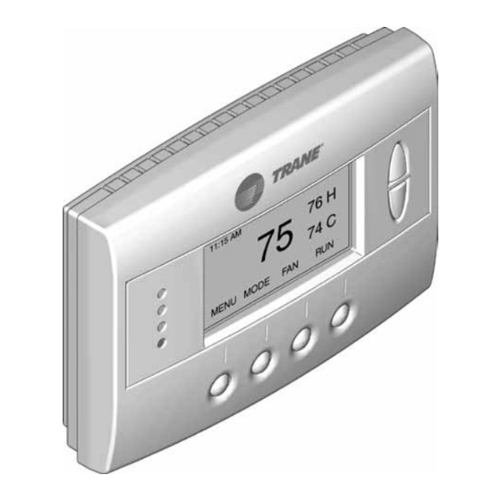
Operation The model TZEMT400AB32MAA and TZEMT500AB32MAA thermostat provide typical thermostat control of a central heating and cooling HVAC system. These thermostats also features a Z-Wave™ module for remote control. Tempurature Display Clock Display 11:15 AM Sys Off Setpoint 77 H... -
Page 18: Thermostat Control Screen Function Control Buttons
Thermostat Control Screen Function Control Buttons Button Description Menu Other thermostat menus can be accessed by pressing the MENU button. System Mode Used to change the system mode: 11:15 AM Sys Off Off: System off 77 H 74 C Heating: Heating only on Filter AUTO AUTO... -
Page 19: Menu Maps
Menu Maps User settings are accessed by pressing the MENU button on the main Installer settings are accessed by pressing the MENU button on the screen. main screen then pressing and holding the two middle buttons until the Installer Settings appear. User Settings Installer Settings (Hidden) Set Clock... -
Page 20: User Settings
User Settings Set Clock The Set Clock screen allows you to set the thermostat’s internal clock. Î Î If the clock has been reset by an extended power outage, the clock display on the thermostat screen will blink. Press the MENU button to go directly to the SetÎClock screen. -
Page 21: Screen Timeout
Maintenance Service The Maintenance Service screen shows the accumulated Heat and Cool Runtime hours as well as the Service Interval that will be used to trigger a Maintenance Message. Any HEAT or COOL type of HVAC operation will cause the respective Runtime values to increase. Maintenance Service When the combined HEAT and COOL Runtime hours equals the Service Heat Runtime... -
Page 22: Usage Graph
F/C Settings The F/C Settings screen is use to select the temperature display mode. Fahrenheit (F) or Celsius (C) are the two available modes. F/C Settings Change the Temperature Mode F/C Mode Press the MENU button. Scroll to UserÎSettings and press the Select button. Scroll to F/CÎSettings and press the Select button. -
Page 23: Esm Setpoints
Backlite/Display The Backlite/Display screen is used to set the backlight time-out and contrast. Backlite Timeout is the time (in seconds) from the last button press to the backlight going out. The time-out can be set between zero (0) and one Backlite/Display hundred and twenty (120) seconds. -
Page 24: Thermostat Info
Thermostat Info The Thermostat Info screen displays information about the thermostat and the system the thermostat controls. This information will be helpful if you need to contact customer support. Item Description TZEMT500AB32 Model Number Ver: 01.00.10 Firmware version (number may vary) Thermostat Info ZVER: 02.00.9 Z-Wave version (number may vary) -
Page 25: Installer Settings
Installer Settings The Installer Settings screen is a hidden screen designed for installer use only. Do not change any settings in this screen unless you are a qualified service technician. Installer Settings Display Lock System Settings Max Heat SP Min Cool SP Done Changing these settings will affect the operation of the heating/cooling system. -
Page 26: System Settings
System Settings Changing these settings will affect the operation of the heating/cooling system. To view and edit these settings: Press the MENU button. Press and hold the two middle buttons simultaneously until the InstallerÎSettings menu is displayed. Scroll to System Settings and press the Select button. Scroll to the setting you want to change. -
Page 27: Mechanical Settings
Mechanical Settings Changing these settings will affect the operation of the heating/cooling system. To view and edit these settings: Press the MENU button. Press and hold the two middle buttons simultaneously until the InstallerÎSettings menu is displayed. Scroll to SystemÎSettings and press the Select button. Scroll to MechanicalÎSettings and press the Select button. -
Page 28: Schedules
Schedules Scheduling is usually controlled by your Z-Wave system. See the instructions that came with your Z-Wave system for more information. However, scheduling may also be controlled by the thermostat. Î The Schedules menu is hidden by default, but may be enabled in the Installer Settings. See Enable/DisableÎtheÎSchedulesÎMenu on Î... - Page 29 View the Current Schedule Press the MENU button. Scroll to Schedules and press the Select button. Scroll to HeatÎandÎCool and press the Select button. The schedule for the current day will be displayed. To view other days, press the Next button. Set a Heat and Cool Schedule Press the MENU button.
-
Page 30: Led Reference
LED Reference The LEDs on the thermostat may have several different meanings, depending on system, setup and operation. 11:15 AM LED 1 Sys Off 77 H LED 2 LED 3 74 C LED 4 Filter MENU MODE On/Off Text Description LED 1 (Green) Sys Off HVAC system is OFF... -
Page 31: Warranty
Parts will be provided by our factory organization through an authorized service organization in your area listed in the yellow pages. If you wish further help or information concerning this limited warranty, contact: Residential Systems 6200 Troup Highway Tyler, TX 75707 Attention: Consumer Relations Or visit our website: www.trane.com/residential TW-1019-5109... - Page 32 Literature Order Number 18-HD39D1-4 File number Trane 18-HD39D1-3 Supersedes 6200 Troup Highway 6/10 Date Tyler, TX 75707 www.trane.com Trane has a policy of continuous product and product data improvement and it reserves the right to change design and specifications without notice.